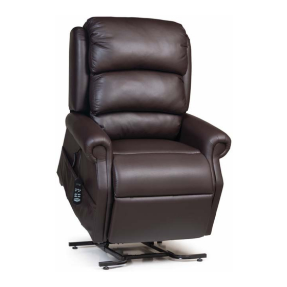
Table of Contents About the Lift Chair Service Guide..…………………………………………………...……….4 Lift Chair Components…………………………………………………………………….....4-6 General Trouble Shooting and Tools Required................7 Models Quick Reference..………………………………………………………………………..8 Replacement Instructions....……………………………………………………………9-21 Smart Tek® Hand Control..………………………………………………………………………..9 Hand Control Extension......................9 Back Assembly..…………………………………………………………………………………10 Control Box....…………………………………………………………………………………11 Lift Motor..……………………………………………………………………………………10-11 Lift Frame....……………………………………………………………………………………11 Arm Assembly...…………………………………………………………………………..12-13 Scissor Mechanism...……………………………………………………………………...13-14 Recline Bar....……………………………………………………………………………..14-15 Seat Assembly...…………………………………………………………………………...15-16...
About the Lift Chair Service Guide This service guide provides you with the information necessary to repair the UltraComfort 3-position, 2-position, and Stellar recline lift chairs. The troubleshooting scenarios in this manual consist of procedures that enable you to systematically trace and correct faults in the system, replacement procedures, and exploded views of available parts.
Page 5
Component: Extension Wire Location: Between the lift frame and the chair frame. Function: Provides connection from the hand control to the motor or control box. Connections: From the quick disconnect in the pocket to the motor or control box. Failure Signs: Chair will not lift/recline.
Page 6
Serviceable: Must be replaced. Battery Back Up System 1. Batteries should be replaced after one use. 2. Batteries should be changed yearly. For a complete explanation of the battery back up system, refer to the UltraComfort owner’s manual. 6 ...
D) Push tube may be stripped or the fork head may be broken. Tools Required: The following tools are needed to service UltraComfort power lift and power recline chairs. • # 8, 9 or 10 flat head screw driver • P2 & P3 Phillips head screw driver •...
Models Quick Reference Main Back Hand Recline Model Series Size Lift Frame Transformer Motor Motor Control Mech. UC214 Leisure Medium LM5000C Maxi None Standard US UC 2 Button 2 way UC332M Leisure Medium LM5100 Maxi None Standard US UC 2 Button...
Replacement Instructions Smart Tek® Hand Control Replacement Tools Needed: None Unplug the transformer from the wall outlet. 2. Reach down into the pocket until you feel the disconnect latch on the extension cable. 3. Pull back on the disconnect latch. 4.
Back Assembly Replacement (500-lb. and 3-position) Tools needed: 7/16 inch socket wrench 1. Press the Down Button on the hand control until the footrest is about parallel to the floor. Unplug the transformer from the wall outlet. 3. Using the 7/16 inch socket wrench, remove the two (2) flange lock nuts located on both sides of the back.
9. Turn the chair over onto the lift frame. 10. Plug the transformer into the wall outlet and test. Lift Frame Replacement Tools needed: Needle nose pliers, T30 Torx screw bit, wire cutters, replacement zip ties, and a chair stand. ...
Arm Assembly Replacement Tools needed: Needle nose pliers, P2 Phillips screwdriver, T30 screw bit, wire cutters, zip ties, 3/8 inch socket, a stool or stand for placing the chair upside down. Unplug the transformer from the wall outlet. 2. Reach down into the chair’s side pocket until you feel the disconnect latch on the hand control extension.
25. Push forward on the disconnecting latch. Make sure it engages fully with the hand control plug base. 26. Clip the Smart Tek® hand control to the black plastic hook on the side of the chair arm. 27. Plug the transformer back into the wall outlet and test. Scissor Mechanism Replacement Tools needed: Needle nose pliers, P2 Phillips screwdriver, T30 screw bit, wire cutters, zip ties, 3/8 inch socket, a stool or stand for placing the chair upside down.
22. Use the hitch pin(s), clevis pin(s), and washers to fasten the recline strap(s) to the recline bar. 23. Use the four (4) T30 lag screws, eight (8) on models (540M-26, 542M-26, 542-ME6, 550-M26) to fasten the lift frame to the arm assembly. 24.
18. Place the lift frame onto the chair shell. 19. Use the hitch pin(s), clevis pin(s), and washers to fasten the recline strap(s) to the recline bar. 20. Use the four (4) T30 lag screws, eight (8) on models (540M-26, 542M-26, 542-ME6, 550-M26) to fasten the lift frame to the arm assembly.
20. Place the lift frame onto the chair shell. 21. Use the hitch pin(s), clevis pin(s), and washers to fasten the recline strap(s) to the lift frame. 22. Use the four (4) T30 lag screws, eight (8) on models (501M26, 501L26, 501T28, 550-M26) to fasten the lift frame to the arm assembly.
Fork Head Replacement Part Number: GMOKI-13 Tools needed: Needle nose pliers, vise-grips, screwdriver, and a cloth. This is the fork head. The fork head is screwed into the push tube of the motor. If you've ever heard the saying for removing and tightening bolts, now think the opposite.
Spacer Bar Replacement (See StellarComfort diagram on page 50.) Tools needed: Needle nose pliers, 7/16” wrench (qty.2) This is what a spacer bar looks like. The spacer bar is located at the rear of the chair across the top of the seat.
Remove the bow-tie clip and slide the pin out. Allow the motor shaft to rest on the floor. Now that you have the 6 nuts removed, the motor is no longer attached; you can remove the back by working the bolts out of the holes on each side of the spacer bar and pushing the back forward onto the seat.
Head Rest Motor Replacement (Model: UC680) Head Rest Motor P/N: GM0900 Tools needed: Needle nose pliers, cutters Step1 Insert the base of the clevis mount at the base of the motor in between the clevis bracket on the back bar insert a 3/8 x 1 5/8, part no. BB5512 clevis pin thru the clevis mount and clevis bracket, lock pin in place with a locking hair pin, part no.
Head Pillow Replacement (Model: UC680) Tools needed: Drill equipped with a 3/8 inch drive bit. Step 1 Press the head up arrow on the hand control until the head rest brackets are completely raised up and exposed above the top of the inside back upholstery.
Scissor Mechanism Parts Component Descrip on RM621 3-Way Recliner Mechs RM622 3-Way Recliner Mechs., HD RM8300 2-Way Recliner Mechs RM620 MaxiComfort Mechs We do recommend both sides be replaced. RM621 RM622 RM620 RM8300...
GM1400-TR Chair Transformer 1400 Richmat GM1501-APUS-36 Transformer Cord Smart Tek® System Models: UC212, UC214, UC332M, UC332L, UC482MED, UC542-JPT, UC542-M, UC542-L, UC480, UC774, UC790, UC992 Note: UC992 is a single motor setup, but uses a special 992 motor not shown. 24 ...
Page 25
Single Motor Electrical Diagram with Headrest Motor REF # PART NUMBER DESCRIPTION QTY. ZK1300-HC Hand Wand, 4 Button Non Maxi Cable 53 inch 5 Pin Male and Motor at Y Female LCMHR-C53 7Pin Quick Release GM1500-LM Motor Chair Okin Maxi Lift Motor GM0901 Motor Headrest Okin JLDQ14 Micro Drive GM2000-TR...
Page 26
Dual Motor Electrical Diagram REF # PART NUMBER DESCRIPTION QTY. ZKUC-20 Hand Wand, Standard 2 Button UltraComfort Extension for Hand Control for ZK1100 2 Button ZK1100-EXT System GMOKI-28W Okin 26-28 Wide Motor GMOKI-CB Motor Chair Okin 26-28 Wide Control Box 4/2003...
Page 28
UC550-M26 Electrical Diagram REF # PART NUMBER DESCRIPTION QTY. ZK756HCL Hand Wand for Maxi Comfort LED GM1502L– B Motor Chair Battery Back Up Wire for GM1501-B with LED GMOKI-28W Okin 26-28 Wide Motor GM756R Motor Chair Okin Recline Motor GMOKI-CB Motor Chair Okin 26-28 Wide Control Box 4/2003 GM2000-TR...
Page 31
STELLAR MOTOR ELECTRICAL SETUP Richmat * Current p/n. REF # PART NUMBER DESCRIPTION QTY. ZKAD-5 Hand Wand Faster AutoDrive Up and M Button ZKAD-1 Hand Wand, AutoDrive for Lift Chairs ZKAD-EXT Hand Control Extension Wire for ZKAD-1 GM1500-LM Motor Chair Okin Maxi Lift Motor GM1450-LM Chair Lift Motor Richmat...
Page 32
STELLAR MOTOR WITH HEAD REST MOTOR ELECTRICAL SETUP Richmat * Current p/n. REF # PART NUMBER DESCRIPTION QTY. ZKAD-HR-1 Hand Wand Fast Auto Drive Head Rest Up and M Button ZKAD-HR Hand Wand Fast Auto Drive With Head Rest LCMHR-C53 Cable 53 inch Two 5Pin Male Y Cable Female 7Pin GM1500-LM...
Page 33
STELLAR MOTOR WITH ECLISPE CONTROL ELECTRICAL SETUP Smart Tek® System Model: UC558-MLA REF # PART NUMBER DESCRIPTION QTY. 1 ZKAD-C3M Hand Wand Auto Drive Cradle 3 Motor Up and M 1 2 ZKAD-EXT Extension Cord for ZKAD-1 1 3 GMC3M-CB ...
Page 34
AUTOLOUNGER MOTOR ELECTRICAL SETUP REF # PART NUMBER DESCRIPTION QTY. ZKRO-1 Hand Wand AutoLounger Recline Only Chairs ZKAD-EXT Hand Control Extension Wire for ZKAD-1 GM1800-LA Motor AutoLounger Lift 6.2 second drive GM1800-RA Motor AutoLounger Recline 8.8 Second Drive GM1800-THD Chair Transformer High Drive w/AC Cord non-Battery BU GM1502-EXTLL Motor chair Extension Wire Low Voltage Led Limoss...
Page 35
WALL HUGGER ELECTRICAL SETUP HAND CONTROLLER MOTOR HAND CONTROLLER EXTENSION WIRE ELECTRICAL OUTLET BATTERY BACK UP WIRE TRANSFORMER REF # PART NUMBER DESCRIPTION QTY. ZKUC-20 Hand Wand Standard 2 Button Ultra Comfort Line ZKUC-20-EXT Extension for Hand Control for ZK1100 2 Button System GM1900 Motor Wall Hugger 992 GM1502L-B Motor Chair Battery Back Up Wire for GM1501-B with LED GM2000-TR...
Page 36
HEAT & MASSAGE ELECTRICAL SETUP – HV3000 REF # PART NUMBER DESCRIPTION QTY. Heat Massage Deluxe Hand Control UltraComfort HV3001-UC Line HV3002-2 Heat Massage Transformer Relaxor w/Wire HV3003-18 Pad, Heat Massage Heating Relaxor 18” HV3004 Heat Massage Seat 1 Vibrator M3M4...
Page 37
HEAT & MASSAGE ELECTRICAL SETUP – HV3100 REF # PART NUMBER DESCRIPTION QTY. HV3100-HC Heat Massage Deluxe Hand Control Relaxor HV3002-2 Heat Massage Transformer Relaxor w/Wire HV3003-18 Pad, Heat Massage Heating Relaxor 18”...
HEAT and MASSAGE ELECTRICAL SETUP – HV4200 REF # PART NUMBER DESCRIPTION QTY. HV4200-HC Hand Control for HV4200 Series HV4200-VIB Massage Motor Vibrator for HV4200 Series HV4200-JBOX Junction Control Box for HV4200 Series HV4200-PADS Heat Pad Small for HV4200 Series (12 inch) HV4200-PADL Heat Pad Large for HV4200 Series (18 inch) GM2000-TR...
Page 39
HEAT and MASSAGE ELECTRICAL SETUP – HV4100 REF # PART NUMBER DESCRIPTION QTY. HV4101-HC Hand Wand, Heat and Massage and Lift HV4101-VIB Massage Back HV4101-PAD Heat Unit HV4101-JBOX Junction Box HV4101-EXT Extension GM1500-LM Motor Chair Led Non Transformer GM2000-TR Motor Chair Transformer GM1501-APUS-36 Transformer Cord...
Page 40
HEAT and MASSAGE ELECTRICAL SETUP – HV4100 REF # PART NUMBER DESCRIPTION QTY. HV4101-HC-NQR Hand Wand, Heat and Massage and Lift HV4101-VIB Massage Back HV4101-PAD Heat Unit HV4101-JBOX Junction Box GM1500-LM Motor Chair Led Non Transformer GM2000-TR Motor Chair Transformer GM1501-APUS-36 Transformer Cord Model: UC480, PL340.
Page 42
HEAT and MASSAGE ELECTRICAL SETUP – HV4000 REF # PART NUMBER DESCRIPTION QTY. HV4001 Hand Wand, Heat and Massage and Lift HV4004B Massage Back HV4003 Heat Unit GM1500-LM Motor Chair Led Non Transformer GM2000-TR Motor Chair Transformer GM1501-APUS-36 Transformer Cord Model: UC480, PL340 Note: The above drawing is for units manufactured prior to May 2012.
Page 46
LM5000C LIFT FRAME PARTS LIST Part Number Description Qty. Per Unit BB5003 Washer, 380 x 750 x 062 Nylon BB5512 Pin, 3/8 x 1 5/8 Zinc Clevis BB5514 Pin, Hitch BB5515 Cap, 1" Square End Chair BB5518 Tywrap, 8" Black ...
Page 47
For use in models U C 3 3 2 M , U C 5 4 2 - J P T , U C 5 4 2 - M , U C 4 8 0 , U C 7 7 4 , U C 5 5 0 - J P T , U C 5 5 0 - M See parts list for specific parts by 47 ...
Page 49
5100 LIFT FRAME LM-RS5100 RECLINE STRAP 5100 / 6111 SERIES LIFT FRAME ZKUC-20 Hand Wand, Standard 2 Button UltraComfort ZKAD-1 Hand Wand Auto Drive for Lift Chairs Note: Refer to “Models Quick Reference” chart for correct hand control by model.
Page 50
For use in models U C 3 3 2 L , U C 4 8 0 - M L A , U C 4 8 2 - M . U C 4 8 4 - M , U C 4 8 6 - M L A , U C 5 4 2 - L , U C 7 9 0 , U C 5 5 0 - L , U C 5 5 6 - S M E , U C 5 5 6 - M L A , U C 5 2 0 - M , U C 8 0 8 See parts list for specific parts by 50 ...
Page 52
LM-RS5100 RECLINE STRAP 5100 / 6111 SERIES LIFT FRAME ZKAD-1 Hand Wand Auto Drive for Lift Chairs ZKUC-20 Hand Wand, Standard 2 Button UltraComfort ZK404-UC Hand Wand Two Button with Lumbar and Headrest UC ZK404-EXT Extension for ZK404-HC Note: Refer to “Models Quick Reference” chart for correct hand control by model.
Page 53
For use in models U C 5 4 2 - M E 6 , U C 5 4 2 - M 2 6 See parts list for specific parts by 53 ...
Page 55
LM6111 LIFT FRAME PARTS LIST Qty. Per Part Number Description Unit BB5003 Washer, 380 x 750 x 062 Nylon BB5512 Pin, 3/8 x 1 5/8 Zinc Clevis BB5514 Pin, Hitch BB5515 Cap, 1" Square End Chair BB5518 Tywrap, 8" Black BB5530 Leg Leveler 5/16 X 1 BB5531...
Page 56
LM5200M-RO (Recline Only) FRAME - AUTOLOUNGER For use in models U C 5 5 1 - M , U C 5 5 1 - L , U C 5 5 7 , U C 5 2 1 - M N o t e : U C 5 5 1 - J P T u s e s a L M 5 2 0 0 M - J P L i f t F r a m e , n o t s h o w n .
Page 57
LM5200M-RO (Recline Only) MOTOR - AUTOLOUNGER ZKRO-1 GM1800‐LA GM1800‐RA GM1800‐RA ‐ not shown in picture. 57 ...
Page 58
LM5200M-RO FRAME PARTS LIST Qty. Per Part Number Description Unit BB5003 Washer, 380 x 750 x 062 Nylon BB5512 Pin, 3/8 x 1 5/8 Zinc Clevis BB5514 Pin, Hitch BB5515 Cap, 1" Square End Chair BB5518 Tywrap, 8" Black BB5530 Leg Leveler 5/16 X 1 BB5531...
Page 59
LM992 LIFT FRAME ASSEMBLY BB5514 BB5513 GM1900 BB5666 BB5663 BB5514 BB5529 BBWASH BB5574 * LM992S or LM992N BB5665 LM992 LIFT FRAME PARTS LIST Qty. Per Part Number Description Unit BB5513 Pin, 3/8 x 2 Zinc Clevis BB5514 Pin, Bow Shaft 72 1/4 Hitch Pin BB5518 Tywrap, 8"...
Page 60
LM5124 LIFT FRAME CRADLE ASSEMBLY For use in model: UC558-MLA 60 ...
Page 61
LM5124 LIFT FRAME CRADLE ASSEMBLY - CONTINUED For use in model: UC558-MLA 61 ...
Page 62
LM5124 LIFT FRAME CRADLE ASSEMBLY – REPLACEMENT Lift Motor Cradle Motor Bolt Bolt Staples Bolt Bolt Back Motor Recline Strap Detent Pin Figure 1 ...
Page 63
LM5124 LIFT FRAME - CRADLE MOTOR Attaching Cradle Motor to Frame Fig 1 Step 1 - Align the back of cradle motor (GM1450-CM) to frame bracket. Insert clevis pin (BB5512) 3/8" x 1 5/8" through frame, two nylon washers (BB5535) 394 x 750 x 125, motor and attach with hair pin (BB5514).
Page 64
LM5124 LIFT FRAME - LIFT MOTOR Attaching Lift Motor to Frame Step 1 - Align the lift motor (GM1450-C3M) with the recline straps. Insert shoulder bolt (BB5590) 3/8" x 2 1/2" through nylon washer (BB5003) 380 x 750 x 062, recline strap, nylon washers (BB5535) 394 x 750 x 125, and (BB5549) 403 x 750 x 312, motor, nylon washers (BB5535) 394 x 750 x 125, and...
Page 65
LM5124 LIFT FRAME - LIFT MOTOR - CONTINUED Step 3 - Actuate motor until recline straps meet the cross bar on top piece of frame. Fig 3 Fig 3 LM5124 LIFT FRAME - CONTROL BOX Attaching the Control Box Fig 1 Step 1 - Place control box (GMC3M-CB) as shown.
Page 66
LM5124 LIFT FRAME - CONTROL BOX - CONTINUED Step 2 - Route the hand control coiled extension along the right-hand side inside rail. Use 8" black Ty wrap (BB5518) in two (2) places on the lower rail. First, in front of the upright, and second in front of the cradle motor as shown.
Page 67
LIFT FRAME - CONTROL BOX - CONTINUED Step 4 - Place a 12" piece of spiral wrap around the motor cables between the elastic hanger and the 3-way splitter as shown. Use one (1) 8" black Ty wrap (BB5518) to secure the cradle coil wire to the other motor wires as shown.
Page 68
When ordering back bolts BB5671 must be Grade 8. Each bolt requires a MS25W split washer and BB5603 lock nut. Each side of the RM756RMB recline bar require a quantity of three of each. For use in models U C 5 5 0 - J P T , U C 5 5 0 - M , U C 5 5 0 - L , U C 5 5 6 - S M E , U C 5 5 6 - M L A , U C 5 2 0 - M , U C 6 8 0 , U C 7 9 2 , U C 5 5 1 - J P T , U C 5 5 1 - M , U C 5 5 1 - L , U C 5 5 7 , U C 5 2 1 See parts list for specific parts by ...
Page 69
Stellar Comfort Recline Mechanism Parts List 69 ...
Power Connections Models: UC212, UC214, UC332M, UC332L, UC542-JPT, UC542-M, UC542-L, UC542-ME6, UC480, UC482-MED, UC484-MED, UC486-MLA, UC774, UC790, UC992, UC550-JPT, UC550-M, UC550-L, UC556-SME, UC556-MLA, UC520-M, UC522, PL340, UC680, UC792 , UC808, UC558-MLA Models: UC542-ME6, UC544-SMA, UC544-MED, UC544-LAR Batteries must be a brand name. Batteries will provide a one time use from recline to the seated position, and then the batteries must be replaced.
Assembly Instructions for Joining Back to Chair Step1: Plug in chair. Step 2: Press the down arrow on the hand control until the footrest is about parallel to the floor. This will expose the back brackets at the rear of the chair. Step 3: Slide the back down between the brackets until the threaded studs on the back slip thru the holes in the brackets as shown.
Page 72
Assembly Instructions for Joining Back to Chair Stellar Comfort Models Step1: Plug in chair. Step 2: Press the recline button on the hand control until the footrest is about parallel to the floor. This will expose the back brackets at the rear of the chair.
Page 74
Hand Controls Lift & Recline and Recline Only - Continued *P/N: ZKAD-CM3 *P/N: ZK404-UC Model: PR486-MLA Model: UC558-MLA Note: For individual switch functions on each hand control, refer to the owner’s manuals. 74 ...
Page 75
Hand Control - Heat & Massage Only P/N: HV3100-UC (DHV System with 2 zones) P/N: HV3000-UC (DHV System with 3 zones) Press PWR to turn On or Off. 15 Minute Timer: Single Press (GREEN) 30 Minute Timer: Press & Hold (ORANGE) Press LO or HI to turn HEAT ON or OFF.
Page 76
Hand Controls - Lift & Recline and Heat & Massage *P/N: HV4101-HC-NQR P/N: HV4101-HC (Cut-in: August 8, 2012 s/n UC or PL 1207F2S12160) GHV system To Operate Lift Press Up key to raise chair. Press DOWN key to lower chair.
AutoFlex Hand Control Automatic Cycling The lumbar can cycle one of three programs by simply pressing the Autostart button 1, 2, or 3 times. See instruction for each below. Note: The automatic feature will cycle for approximately 12 minutes ...
AutoFlex Wiring Diagram Lumber Auto Flex Hand Control Control Box Transformer Transformer Plug Control Box Extension DWG # PART NUMBER DESCRIPTION MECH-LMBAF-MED Mech Lumbar Auto Flex System Med ZKLMB-AF Hand Wand Lumbar Auto Flex GMLMBAF-CB Control Box Lumbar Auto Flex System GMLMBAF-CB-EXT Control Box Extension Lumbar Auto Flex GMLMBAF-TRAN...
Shiatsu Hand Control Shiatsu Operation 1. Press the ON/OFF button to startup the massage. The rolling indicator will be on, signaling the direction the unit is operating. Default timer is 15 minutes. 2. Press the TIMER button to manually switch from 5 to 30 minutes of operation.
Shiatsu Component Replacement Tools Required: Phillips screwdriver, 3/8” wrench, 7/16” wrench, wire cutter, and staple puller. Refer to figure 1 and follow the step-by-step instructions below for Shiatsu massage unit replacement. Shiatsu massage unit removal / installation Step 1 – Remove the power source by unplugging the chair from the AC wall outlet. Step 2 –...
Page 82
Refer to figure 2 and follow the step-by-step instructions below for control box or extension wire replacement. Control box removal / installation Step 1 – With the chair upside down, run the chair hand control to raise the frame enough to access the control box.
UC486-MLA Hand Control & Wiring Headrest Lumbar Motor Motor Lift Motor Lift Motor P/N: ZK404-EXT Item No Descrip on Qty. GM1410-LM Chair Lift Motor 1410 1 LM5120 LM5120 Lift Frame 1 ZK404-EXT Extension for ZK404-HC 1 GM1410-TR Chair Transformer 1410 1 ...
Grease Points Appling any type of lubricant as a routine maintenance procedure is not necessary. If lubricating the lift chair to alleviate excessive noise, only apply the specified lubricant at the locations shown below. Do not apply excessive lubricant. Excessive lubricant could leak onto the chair or the floor causing damage.
Need help?
Do you have a question about the UC214 and is the answer not in the manual?
Questions and answers