Table of Contents
Advertisement
Quick Links
Advertisement
Table of Contents

Subscribe to Our Youtube Channel
Related Manuals for CHC X360


Summary of Contents for CHC X360
- Page 1 Safety Information CHC X360 GIS Receiver Revision 1.0 January 2015...
- Page 2 (1) this device may not cause harmful interference and (2) this device must accept any interference received, including interference that may cause undesired operation. X360 GIS Receiver User Guide – Revision 1.0 January 2015 X360 GIS Reference Receiver User Guide Page...
-
Page 3: Type Approval
AFETY NFORMATION Before you use your CHC X360 GIS Receiver, make sure that you have read and understood all safety requirements. EGULATIONS AND SAFETY The Receiver contains an internal wireless modem for communicating signals through Bluetooth® wireless technology or through an external data communications radio. - Page 4 Do not operate the equipment near electrical blasting caps or in an X360 GIS Reference Receiver User Guide Page...
- Page 5 Discontinue charging a battery that gives off extreme heat or a burning odor. Use the battery only in CHC equipment that is specified to use it. Use the battery only for its intended use and according to the instructions in the product documentation.
-
Page 6: Dc Power Supply Safety
WARNING – Do not power the Receiver through external power when operating in a wet environment or an environment that may become wet. The power input connections must be sheltered. X360 GIS Reference Receiver User Guide Page... - Page 7 System installation diagram....................20 5. Configuring the Receiver: Other Than Keypad and Display ............... 22 A. Configuring the Ethernet settings....................22 B. Configuring through a web browser ....................23 • Changing the settings ......................24 X360 GIS Reference Receiver User Guide Page...
- Page 8 Upgrading through a browser ..................... 52 Troubleshooting ............................53 • Receiver issues ..........................53 Communication Ports Definition ....................... 55 CHC X360 Receiver DB9 Male Connector Definition ................55 Glossary ..............................56 X360 GIS Reference Receiver User Guide Page...
-
Page 9: Introduction
A. I NTRODUCTION The X360 GIS Receiver User Guide describes how to set up and use the CHC X360 GIS Receiver. In this manual, “the Receiver” refers to the X360 GIS Receiver unless otherwise stated. Even if you have used other Global Navigation Satellite Systems (GNSS) products before, CHC recommends that you spend some time reading this manual to learn about the special features of this product. - Page 10 ISCLAIMER Before using the Receiver, please make sure that you have read and understood this User Guide, as well as the safety requirements. CHC holds no responsibility for the wrong operation by users and for the losses incurred by the wrong understanding about this User Guide. However, CHC reserves the rights to update and optimize the contents in this guide regularly.
-
Page 11: Overview
B. O VERVIEW This chapter introduces the X360 GIS Receiver (“the Receiver”). This Receiver makes it easy to set up a powerful and reliable Continuously Operating Station (CORS) or to collect data from temporary field locations. The Receiver is ideal for the following infrastructure applications: ... -
Page 12: Batteries And Power
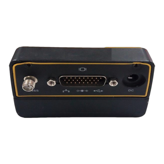
Anyone with authorized access can obtain streamed information, such as GNSS measurements or RTCM corrections, without having to control or issue commands to the Receiver. The client simply connects to the port that is streaming the required information. X360 GIS Reference Receiver User Guide Page 10... - Page 13 CAUTION – Operating or storing the Receiver outside the specified temperature range can damage it. For more information, see Chapter 8 Specifications. B.V. E LECTRONIC INTERFACE X360 GIS Reference Receiver User Guide Page 11...
- Page 14 Receiver operations. B.VI. K EYPAD AND DISPLAY Feature Description Power Shows if the power is on or off. Buttons 1,Battery 2,satellites 4,Upload LED 5,Downloading LED X360 GIS Reference Receiver User Guide Page 12...
- Page 15 Power from an external AC/DC power supply. RS-232 serial communications using a 10- pin Lemo cable (CHC Data Cable). Pass-through to the mainboard without issuing the pass-through command via this port. X360 GIS Reference Receiver User Guide Page 13...
- Page 16 The X360 GIS Receiver uses an internal rechargeable Lithium-ion battery, which can be replaced only at an Authorized CHC Service Center. The Receiver can also be powered by an external power source that is connected to either of the Lemo ports.
- Page 17 The Receiver’s internal battery charges only when the external voltage is above 11 V DC. CHC recommends that the applied external power offers between 12 V DC and 36 V DC and is able to supply at least 4 W of power for the long-term installations and ensuring that the internal battery is charged and ready to compensate for power supply disruptions.
- Page 18 To prevent injury or damage: 6. Do not charge or use the battery if it appears to be damaged or leaking. 7. Charge the Lithium-ion battery only within the X360 Receiver. The X360 GIS Reference Receiver User Guide Page 16...
- Page 19 C.VI. R EMOVING THE BATTERY The internal Lithium-ion battery may be removed only at an authorized CHC Service Center. If the battery is removed at an unauthorized service center, the remaining warranty on the product will be void. X360 GIS Reference Receiver User Guide...
- Page 20 This chapter describes best practices for setting up the equipment, and outlines the precautions that you must take to protect the equipment. It also describes the typical installation diagram of station composed of X360 GIS Receiver, GNSS antenna, external power and network cable.
- Page 21 LACING THE ANTENNA The antenna location will have a significant effect on the quality of your X360 Receiver's performance. In temporary developments it may not always be possible to set up on an ideal location with an excellent sky view.
- Page 22 YSTEMINSTALLATION • UPPORTED ANTENNA The Receiver provides a TNC-type female connector for connecting to an antenna. The Receiver is intended for use with a CHC Geodetic GNSS antenna or a CHC GNSS Choke Ring antenna. CHC Helical GNSS Antenna Other GNSS antennas may however be used ensuring that the antenna receive the proper GNSS frequencies and operates at either 3.3V or 7.1V...
- Page 23 Power the X360 by external power source (e.g. mains supply) with Adapter via CHC Data Cable. Connect the 10-pin Lemo of CHC Data Cable to COM 1 or COM 2 of X360. Plug the male jack connector of Adapter into the female connector of CHC Data Cable.
-
Page 24: Setting Up The Receiver
THER EYPAD AND ISPLAY You can configure the X360 , GIS Receiver to perform a wide variety of functions. This chapter describes the configuration methods other than the front panel display, and explains when and why each method is used. -
Page 25: Configuring The Receiver: Other Than Keypad And Display
NOTE: Tick remember me option, and then the browser will remember the Login Account and Password you entered for the next time you enter this login screen. Once you are logged in, the web page appears as follows: X360 GIS Reference Receiver User Guide Page 23... -
Page 26: Status Menu
Currently, three languages are available: • Status menu This menu provides a quick link to review the Receiver's position information, satellites tracked, runtime, current data log status, current outputs, available memory, and more. • Position X360 GIS Reference Receiver User Guide Page 24... - Page 27 Receiver has been operational, state of the internal battery, power source state, files being logged, and data streams being output. With this information, it is easy to tell exactly what functions the Receiver is performing: X360 GIS Reference Receiver User Guide Page 25...
- Page 28 6. Configuring the Receiver: Other Than Keypad and Display • Google map Tap this submenu to show the location of the Receiver on Google map. X360 GIS Reference Receiver User Guide Page 26...
-
Page 29: Satellites Menu
Satellite Track Diagram The following figure is an example of satellite track diagram page. Users can determine the satellite types and the corresponding SNR of L-band carriers to be displayed in any combination. X360 GIS Reference Receiver User Guide Page 27... - Page 30 6. Configuring the Receiver: Other Than Keypad and Display • SkyPlot The following figure is an example of Skyplot page. • Satellite Settings In this submenu, users can enable/disable GPS constellations. X360 GIS Reference Receiver User Guide Page 28...
-
Page 31: Receiver Settings Menu
Use this screen to configure all of the items relating to the GNSS antenna. You must enter the correct values for all antenna-related fields, as the choices you make significantly affect the accuracy for logged data X360 GIS Reference Receiver User Guide Page 29... - Page 32 RTK correctors based on coordinates obtained through single-point positioning automatically. • Manual Base: The Receiver will serve as Base after the restart, and then broadcast RTK correctors based on the coordinates before power off. X360 GIS Reference Receiver User Guide Page 30...
- Page 33 Also, users can click to save the curent settings. • Receiver Reset Use this screen to completely or partially reset the Receiver: • Languages X360 GIS Reference Receiver User Guide Page 31...
-
Page 34: Data Recording Menu
Shows the data logging status, internal and external storage usage and data logging status of each storage thread. Also, users can configure the data logging settings for each storage thread, including recording name, saving location, storage limit, store formats, start time, etc. X360 GIS Reference Receiver User Guide Page 32... - Page 35 Master Log Switch is OFF. To edit the settings of each storage thread, click the [Modify] button to the right of the required storage thread, and then the Recording Edit screen appears: X360 GIS Reference Receiver User Guide Page 33...
- Page 36 Only files that are configured to use FTP push are transmitted. Click [Modify] button to the right of the required FTP server and the FTP Push Settings screen appears: X360 GIS Reference Receiver User Guide Page 34...
- Page 37 The default logon account for the internal FTP site is: 5.1. User name: ftp 5.2. Password: ftp Click the directory named as repo to view and download the files X360 GIS Reference Receiver User Guide Page 35...
- Page 38 6. Configuring the Receiver: Other Than Keypad and Display currently stored on the Receiver: X360 GIS Reference Receiver User Guide Page 36...
- Page 39 Receiver can output CMR, RTCM, Raw data, Ephemeris data, GPGGA, GPGSV, on TCP/IP, UDP, serial port, or Bluetooth ports. • IO Settings The following figure shows an example of the screen that appears when you select this submenu. X360 GIS Reference Receiver User Guide Page 37...
- Page 40 choose one of the connection protocols among the NTRIP, APIS_BASE and APIS_ROVER configure the related parameters click to log on CORS or APIS. A. Connection Protocol: NTRIP B. Connection Protocol: APIS_BASE X360 GIS Reference Receiver User Guide Page 38...
- Page 41 enter the IP and Port of the target server configure messages that you want to output to the target server click to save and complete the connection. X360 GIS Reference Receiver User Guide Page 39...
- Page 42 IO Settings screen will appear select one of the connection protocols between NTRIP and TCP configure the other related parameters click to save the settings and open the server. Connection Protocol: NTRIP Connection Protocol: TCP X360 GIS Reference Receiver User Guide Page 40...
- Page 43 Click the [Settings] button to the right of Bluetooth the Bluetooth Set screen will appear configure the messages that you want to transmit through Bluetooth click to save the settings and start to transmit. X360 GIS Reference Receiver User Guide Page 40...
- Page 44 The following figure shows an example of the screen that appears when you select this submenu: • Network Set Use this submenu to configure the related parameters of the Network, including static IP, subnet mask, etc. X360 GIS Reference Receiver User Guide Page 41...
-
Page 45: Wifi Menu
Wi-Fi mode, encrypt type, password, etc. • Bluetooth Set menu Use this menu to configure Bluetooth settings. • Bluetooth Set The following figure shows an example of the screen that appears when X360 GIS Reference Receiver User Guide Page 42... -
Page 46: Network Service Menu
Receiver firmware, download or update the configuration file and register the Receiver. • Firmware Info Use this submenu to check the current firmware information. The following figure shows an example of the firmware information. X360 GIS Reference Receiver User Guide Page 43... - Page 47 (.cfg file). Also, users can click the [Browse] button to locate the existing configuration file click [Confirm] button to confirm the selected file and start updating. X360 GIS Reference Receiver User Guide Page 44...
- Page 48 6. Configuring the Receiver: Other Than Keypad and Display • GNSS Registration Use this submenu to register the Receiver. Paste or enter the registration code to the Registration Code field click [Registration] button to complete the registration. X360 GIS Reference Receiver User Guide Page 45...
- Page 49 Most of the Receiver settings are stored in application files. The default application file, Default.cfg, is stored permanently in the Receiver, and contains the factory default settings for the X360 GIS Receiver. Whenever the Receiver is reset to its factory defaults, the current settings (stored in the current configuration file, copy.cfg) are reset to the values in...
- Page 50 Log in the web page of the Receiver tap and unfold the Firmware menu tap the Config File submenu click the [Browse] button to locate the existing configuration file click [Confirm] button to confirm the selected file and start updating. X360 GIS Reference Receiver User Guide Page 47...
-
Page 51: Specifications
– PECIFICATIONS This chapter describes the specifications for the X360 GIS Receiver. Specifications are subject to change without notice. GNSS • CHARACTERISTICS Feature Specification – Tracking 220 channels • GPS: L1 C/A, L2C, L2E, L5 – Pseudo-range measurement with high- precision multi-correlator –... - Page 52 Up to 10 hours continuous operation, dependent on user setting internal battery • ENERAL Feature Specification Receiver type Receiver Antenna type CHC A220GR GNSS Geodetic antenna or CHC C220GR GNSS Choke Ring antenna preferred. Other models supported. • ATA STORAGE X360 GIS Reference Receiver User Guide Page...
- Page 53 Supporting USB drive or portable hard drive Storage method 8-thread logging, circulating data logging Data format HCN, RINEX, original binary data Data download FTP push, online download, storage on an external USB devices X360 GIS Reference Receiver User Guide Page 50...
-
Page 54: The Winflash Utility
YYYYMMDD represents the firmware encapsulation date. 1.1. T LASH UTILITY The WinFlash utility communicates with CHC products to perform various functions including: load or verify GPS software of the mainboard update or verify the Receiver options For more information, online help is also available when using the WinFlash utility. - Page 55 6.2.1.10 F irmware Firmware Update menu for detail operation steps. NOTE: After the Receiver firmware upgrading, the IP information may be changed. Please confirm the IP setting of the Receiver before using it. X360 GIS Reference Receiver User Guide Page 52...
- Page 56 – ROUBLESHOOTING Use this appendix to identify and solve common problems that may occur during the use of the Receiver. Please read this section before you contact CHC Technical Support. RECEIVER • ISSUES This section describes some possible Receiver issues, possible causes, and how to solve them.
-
Page 57: Troubleshooting
Make sure that the GNSS antenna is located with a not in clear line of clear view of the sky. sight to the sky. Restart the Receiver as a last resort (turn off and then turn it on again). X360 GIS Reference Receiver User Guide Page 54... - Page 58 CHC X360 Receiver DB9 M ONNECTOR EFINITION Signal Description Name Not Used RS232-TX (transmit data through this pin) RS232-RX (receive data through this pin) Not Used External Power Ground Not Used Not Used Not Used Not Used X360 GIS Reference Receiver User Guide Page...
-
Page 59: Glossary
The angle below which the Receiver will not track satellites. Normally set to 10 degrees to avoid interference problems caused by buildings and trees, and multipath errors. X360 GIS Reference Receiver User Guide Page... - Page 60 National Marine Electronics Association. NMEA 0183 defines the standard for interfacing marine electronic navigational devices. This standard defines a number of 'strings' referred to as NMEA strings that contain navigational details such as positions. Most CHC GPS Receivers can output positions as NMEA PDOP strings.
- Page 61 GPS Receivers. There are three versions of RTCM correction messages. All CHC GPS Receivers use Version 2 protocol for single-frequency DGPS type corrections. Carrier phase corrections are available on Version 2, or on the newer Version 3 RTCM protocol, which is available on certain CHC dual-frequency Receivers.
- Page 62 To start using VRS corrections, the rover sends its position to the VRS server. The VRS server uses the station data to model systematic errors (such as ionospheric noise) at the rover position. It then sends RTCM or CMR correction messages back to the rover. X360 GIS Reference Receiver User Guide Page...
- Page 63 Battery Charging: Please use the applicable adapter with the required specifications to charge the X360 GIS Receiver. Please plug in the adapter and connect the DC port to X360 GIS Receiver. Specifications of the adaptor: input 100~240V, 50/60Hz, 2.0A Output 12V. 1.5A GIS Receiver placed in the fixed outdoor use, will not carry.
- Page 64 FCC Statement 1. This device complies with Part 15 of the FCC Rules. Operation is subject to the following two conditions: (1) This device may not cause harmful interference. (2) This device must accept any interference received, including interference that may cause undesired operation. 2.
Need help?
Do you have a question about the X360 and is the answer not in the manual?
Questions and answers