Table of Contents
Advertisement
Quick Links
Advertisement
Table of Contents

Related Manuals for Timeguard MLSA360NP


Summary of Contents for Timeguard MLSA360NP
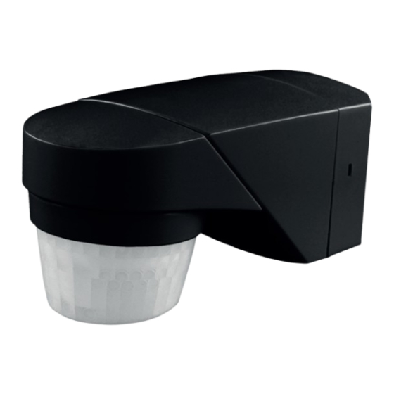
- Page 1 Multiway Mounting PIR Light Controller Model: MLSA360NP...
-
Page 2: General Information
1. General Information These instructions should be read carefully and retained for further reference and maintenance. Timeguard reserve the right to alter these instructions Note: at any time. Up to date instructions will always be available for download at www.timeguard.com 2. - Page 3 • Max Mounting Height: 2.5 metres • Mounting Modes: Ceiling, Surface, Internal and External Corner Mount • Detection Angle: 200º Front 12m at 2.5m height. • Anti-Creep Detection: 360º Downward Ø5m at 2.5m • Time ON Adjustment: 1- 20 minutes •...
-
Page 4: Selecting A Location
4. Selecting a location • The PIR has a number of detection zones at various horizontal and vertical angles as shown below. Effective Approach Path Ineffective Approach Path (ACROSS) (TOWARDS) • A moving human body or object needs to cross one of these zones to activate the sensor. -
Page 5: Installation
• During extreme weather conditions the PIR may exhibit unusual behaviour. Once normal weather resumes, the PIR will carry out normal operations. 5. Installation • Ensure the mains supply is switched off and the circuit supply fuses are removed or the circuit breaker turned off. •... - Page 6 • If the PIR is going to be used on a internal or external corner mounting position use the appropriate knockouts to line up the wall plate to be used as a template to mark the position of the fitting holes. Drill the holes. Then, insert the rawl plugs into the holes.
-
Page 7: Connection Diagram
6. Connection Diagram 230V 50Hz AC Mains Connection Diagram Use the earth (loop) For 230V 50Hz mains terminal to join the switching a link cable must supply and load if be used between terminals earth continuity is required. “L” and “D1”. ISOLATION SWITCH Load Supply... - Page 8 7. Walk Test & Automatic Operation • Restore the power from the mains supply breaker or isolating switch and test for the correct operation. • Once the PIR’s pan and tilt angles have been set, adjust the time dial (fully clockwise), to test mode. This should bypass the photocell so the walk test can commence at day or night periods.
-
Page 9: Manual Override Operation
Masking the Sensor Lens • To restrict the sensor coverage, preventing detection in unwanted areas, mask the sensor lens using the masks provided in the accessory pack (see diagram below). • The top section of the lens covers long range detection, the bottom covers short range. -
Page 10: Pulse Mode
9. Dusk To Dawn Mode • To enable dusk to dawn mode, twist the arrow head on the time delay dial to point to “D”. • When in dusk to dawn mode the lux level you set will determine when the PIR enters and exits dusk to dawn mode. -
Page 11: Troubleshooting Guide
3 or with any difficulty in the first year, telephone our helpline. Note: a proof of purchase is required in all cases. For all eligible replacements (where agreed by Timeguard), the customer is responsible for all shipping/postage charges outside of the UK. - Page 12 If you experience problems, do not immediately return the unit to the store. Email the Timeguard Customer Helpline: HELPLINE helpline@timeguard.com or call the helpdesk on 020 8450 0515 Qualified Customer Support Coordinators will be online to assist in resolving your query.
Need help?
Do you have a question about the MLSA360NP and is the answer not in the manual?
Questions and answers