
Related Manuals for Parker 6250


Summary of Contents for Parker 6250
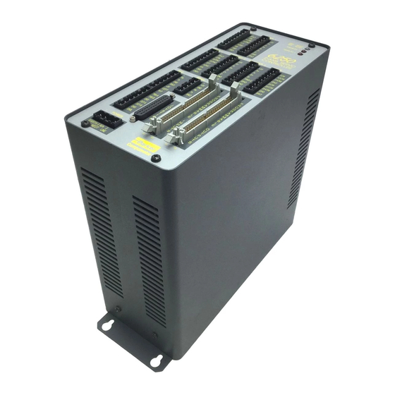
- Page 1 6250 Servo Controller User Guide Compumotor Division Parker Hannifin Corporation p/n 88-013413-01B October 18, 1993...
- Page 2 The information in this user guide, including any apparatus, methods, techniques, and concepts described herein, are the proprietary property of Parker Compumotor or its licensors, and may not be copied, disclosed, or used for any purpose not expressly authorized by the owner thereof.
- Page 3 S e e A l s o 6250-ANI Analog Input Option New Option/Feature: The 6250-ANI option was released at the same Pg. 16, 54 & time this user guide revision B was released. The -ANI option is a ±10V, 14-...
- Page 4 DCLEARØ command. This version of the user guide was released at the same time that revision Software Revision 1.1 1.1 of the 6250 software was released. Released New Feature: The VCVT( ) command has been added to allow you to Variable Type Conversion Pg.
-
Page 5: Table Of Contents
Programmable Inputs & Outputs Connections................13 Trigger Input Connections....................14 RP240 Front Panel Connections.................... 15 Joystick and Analog Input Connections.................. 15 ANI Analog Input Connections (6250-ANI Option Only).............. 16 Extending 6250 System Cables .................... 17 Installation Verification ....................... 17 What's Next? ..........................19 Chapter 4: Servo Tuning . - Page 6 Input Functions ......................... 58 Thumbwheel Interface......................63 PLC Interface........................65 Joystick Interface.......................... 65 -ANI 14-Bit Analog Input Option (6250-ANI Option Only) ................ 68 RP240 Front Panel Interface ......................68 Operator Interface Features....................69 Using the Default Mode ....................... 70 Host Computer Operation ........................ 72 Variables (Binary, Numeric, and String) ....................
-
Page 7: Overview
Contents of This User Guide Chapter Purpose Introduction Describes the 6250 and provides a brief account of its features. Getting Started Lists and describes the items you should have received with your 6250 shipment. A bench test procedure is provided to verify the system's basic functionality. -
Page 8: Installation Process Overview
After you successfully complete all procedures in Chapter 3, you will be ready to proceed to Chapter 4, Servo Tuning, to tune the drive and the 6250 for your application. The tuning procedures in Chapter 4 are based primarily on using the Servo Tuner option for Motion Architect. -
Page 9: Introduction
(DSP) for high-speed, sophisticated servo control. This dual processor approach allows commands to be executed faster. Using the 6000 Series Programming Language, you can program the 6250 via a PC or a dumb terminal. User programs are stored in the 6250's battery-backed RAM. -
Page 10: 6250 Features
• 24 programmable outputs (Opto-22™ compatible) • 2 auxiliary programmable outputs that can be configured for accurate output on position within ±1 count 6250-ANI Option offers two ±10V, 14-bit analog inputs (one per axis) with anti-aliasing filter. 6250 Servo Controller User Guide... -
Page 11: Getting Started
8-foot AC power cord * The 6250-ANI is an optional version of the 6250 which provides two ±10V, 14-bit analog inputs. If you ordered a -ANI option, check the serial tag on the side of the 6250's chassis; it should say 6250-ANI. -
Page 12: Bench Test
XON/XOFF: Enabled If your terminal is not capable of 9600 baud, use the 6250's auto-baud function to automatically set the 6250's baud rate equal to the terminal's baud rate. Refer to Optional DIP Switch Settings in Chapter 8 for instructions. -
Page 13: Connect Power Cable
Connect Power Cable The 6250 is shipped with an 8-foot power cable that is prewired and keyed. Attach the power cable to the 6250's connector as illustrated below. POWER WARNING 2 - A X I S S E R V O... -
Page 14: Installation
Always remove power to the 6250 before performing wiring installation or changing DIP switch settings. Heat & Humidity Operate the 6250 system at an ambient temperature between 32° and 122°F (0° to 50°C). Keep the relative humidity below 95%. Electrical Noise Minimize the potential for electrical noise before installing the 6250, rather than attempting to solve such problems after installation. -
Page 15: Mount The 6250
(4 Plcs.) Panel Layout If you mount the 6250 in an enclosure with other equipment, be sure to maintain at least 2 inches of unrestricted air-flow space around the chassis. The maximum allowable ambient temperature directly below the 6250 is 122°F (50°C). Fan cooling may be necessary if adequate air flow is not provided. -
Page 16: Motor Driver Connections
CAUTION Before connecting to your Motor/Drive system, be sure that power is not applied to the 6250. The 6250 provides a standard ±10V analog control signal for use with any servo drive. The following table lists the 6250's motor driver connector pin outs;... - Page 17 VIN (pin 49) CMD+ ↔ AGND (pin 50) CMD– CHA+ CHA– NOTE: CHB+ CHB– Apex Series A+ connected to 6250’s A– CHZ+ Apex Series A– connected to 6250’s A+ CHZ– 6250 BL Drive User I/O Connector DRIVE 1 ENCODER 1 SHLD...
- Page 18 If a drive fault occurs, you must cycle power to the drives, unless you control RESET factory default position). (PL9 pin 8 on UR4 & UR8 racks, PL4 pin 8 on UR3 rack) with one of the 6250’s general-purpose outputs. For additional instructions on detecting and reacting to UD rack faults, contact the Compumotor or Digiplan Applications Department.
- Page 19 If a drive fault occurs, you must cycle power to the drives, unless you control RESET (pin 8 on the PL9 connector) with one of the 6250's general-purpose outputs. For additional instructions on detecting and reacting to UD rack faults, contact the Compumotor or Digiplan Applications Department.
-
Page 20: End-Of-Travel Limit Connections
If a runaway occurs (motor starts moving, usually at the fastest possible velocity, due to servo instability), the 6250 will shut down the drive if the maximum encoder position error (set with the SMPER command) is exceeded before an end-of-travel limit (either hardware of software) is encountered. -
Page 21: Encoder Connections
The illustration below shows the wiring techniques that you must use to connect encoders to the 6250. Refer to Chapter 8 for the 6250's encoder input circuit drawing. If you are using the BL or Dynaserv drives, refer to the connection illustrations earlier in the Motor Driver Connections section. -
Page 22: Enable Input Connection
All 26 programmable outputs are pulled up using the pin on the connector (see OUT-P illustration above). The 6250 is factory wired for +5VDC logic. If +5VDC is not to be used, disconnect from the terminal and connect OUT-P to an external supply of up to OUT-P 24V. -
Page 23: Trigger Input Connections
The VM50 simply PROGRAMMABLE INPUTS PROGRAMMABLE OUTPUTS attaches to the 6250 via the 2-foot, 50-pin ribbon cable that comes with the VM50 (see drawing below). To order the VM50, contact your distributor or ATC, or call Compumotor at (800) 722-2282. -
Page 24: Rp240 Front Panel Connections
For the 6250 to recognize the RP240, the RP240 connection must be made prior to powering up (or resetting) the 6250. If you connect the RP240 to the 6250 before powering up the 6250, the 6250 will recognize the RP240 and send the *RP24Ø CONNECTED message to the RS-232C terminal. -
Page 25: Ani Analog Input Connections (6250-Ani Option Only)
Refer to the illustration above. When this input is not connected, the low velocity range is selected. Joystick Release The joystick release input allows you to indicate to the 6250 that you have finished using the Input joystick and program execution may continue with the next statement. When a program... -
Page 26: Extending 6250 System Cables
Compumotor E Series encoders are supplied with a permanently attached 10-foot cable. The Cables maximum cable length between Compumotor encoders and the 6250 is 100 feet. If you wish to lengthen the encoder cable yourself, use 24 AWG wire. Encoder cables should be shielded... - Page 27 Set all the gains to zero by entering the following: SGPØ,Ø, SGIØ,Ø, SGVØ,Ø, SGAFØ,Ø, SGVFØ,Ø Enable the 6250 to send out the analog command by entering the DRIVE11 command. Set the DAC output limit to 10 volts by entering the DACLIM1Ø,1Ø command.
-
Page 28: What's Next
At this point you should have successfully completed this chapter's mounting, connection, and test procedures for your 6250 system. If you intend to use thumbwheels or PLCs, or if you intend to daisy-chain multiple 6250s, refer to the connection instructions and application considerations provided in Chapter 5. - Page 29 Once you have done that, you can proceed to Chapter 4 to tune the 6250, and Chapters 5 through 7 to find out how to implement the 6250's motion control features in your application.
-
Page 30: Servo Tuning
Compumotor 6250 Servo Controller. Servo Tuning Terminology The 6250 uses a digital control algorithm to control and maintain the position and velocity. The digital control algorithm consists of a set of numerical equations used to periodically (once every servo sampling period) calculate the value of the control signal output. -
Page 31: Position Variable Terminology
Load Encoder The 6250 has the capability of providing a ±10V analog voltage output for commanding the motor's drive. After the digital control algorithm has calculated the digital control signal, this digital value is sent out from the DSP (digital signal processor) to the Digital-to-Analog converter (DAC). -
Page 32: Servo Response Terminology
Setpoint Profile Complete Commanded Position Distance ( D ) Constant Acceleration Deceleration Velocity Time Actual Position The other type of time-varying position information is the actual position; that is, the actual position of the motor/load measured with the encoder. Since this is the position achieved when the motor responds to the commanded position, we call the overall picture of the actual position over time the position response (see further discussion under Servo Response Terminology). - Page 33 A typical stable position response plot in preset mode (MCØ) is shown below. Settling Time Target Zone Mode Settling Band Setpoint Setpoint Commanded Overshoot Steady State Position Position Error Actual Position Rise Time Transient Steady State Time 6250 Servo Controller User Guide...
-
Page 34: 6000 Series Servo Commands
Sets the maximum allowable error between the commanded position and the actual SMPER position as indicated by the encoder. If the error exceeds this limit, the 6250 shuts down the motor drive with the Shutdown output. You can enable the ERROR command to continually check for this error condition, and when it occurs to branch to a programmed response defined in the ERRORP program. -
Page 35: Servo Control Techniques
To ensure that you are tuning your servo system properly, you should understand the tuning techniques described in this section. The 6250 employs a PIV&F servo control algorithm. The control techniques available in this system are as follows: P ..Proportional Feedback (controlled with the SGP command) I .. -
Page 36: Integral Feedback Control (Sgi)
Integral Feedback Control (SGI) Using integral feedback control, the value of the control signal is integrated at a rate proportional to the encoder position error. The rate of integration is set by the Servo Gain Integral (SGI) command. The primary function of the integral control is to overcome friction and/or gravity and to reject disturbances so that steady state position error can be minimized or eliminated. -
Page 37: Velocity Feedforward Control (Sgvf)
Algorithm drawing above), it does not affect the servo system's stability. Therefore, there is no limit on how high the velocity feedforward gain (SGVF) can be set, except when it saturates the control output (tries to exceed the 6250's ±10V analog control signal range). Acceleration Feedforward Control (SGAF) The purpose of acceleration feedforward control is to improve position tracking performance when the system is commanded to accelerate or decelerate. -
Page 38: Tuning Setup Procedure
DRIVEØØ command. If your motor drive does not have a shutdown input, use a manual emergency stop switch to shutdown the drive's power supply. You can also use the E N B L input to disable the 6250's analog output signal. - Page 39 Step 2. If the noise level is still unacceptable, consult the noise suppression techniques described in Appendix A. S t e p 7 The purpose of this step is to ensure that a positive voltage on the 6250's analog control signal output (from the terminals) results in the encoder counting in the...
-
Page 40: Drive Tuning Procedure (Velocity Drives Only)
20 rps/V, then the drive will reach the maximum velocity (116.67 rps) when the 6250's command output is only 5.833V. This means the full range of ±10V is not fully usable. To use the full range of ±10V, the gain factor has to be adjusted to 11.667 rps/V. -
Page 41: Controller Tuning Procedure
Actual Velocity Time S t e p 4 Proceed to the Controller Tuning Procedure section to tune the 6250. Motion Architect Automatic Gain Selection Feature The drive scale factor and step response information gathered in the latest Drive Tuner module session can be used in the Controller Tuner module to automatically select gains that should greatly shorten the iterative nature of the controller tuning process. - Page 42 S t e p 2 Select the 6250's sampling frequency ratios (SSFR): The 6250's control signal is computed by the digital signal processor (DSP). The velocity of the commanded position, the velocity of the encoder position, and the integral of the position error are used for various control actions.
- Page 43 Commanded Position Time horizontal axis. Select and use as the vertical axis and Graph 2 Actual Position Time as the horizontal axis. (Make sure both Graph 1 Graph 2 are enabled to be displayed.) Click 6250 Servo Controller User Guide...
- Page 44 S t e p 4 Optimize the Proportional (SGP) and Velocity (SGV) gains ( see illustration for tuning process ): If you are not using Motion Architect: Enter the following commands to create a step input profile (use a comma in the first data field when tuning axis 2—e.g., D,5Ø) : Co mma n d De s c r i p t i o n...
- Page 45 START Increase SGP UNTIL Decrease SGV Increase SGV UNTIL UNTIL Decrease SGV UNTIL STOP Decrease SGP UNTIL Increase SGV UNTIL Decrease SGV UNTIL 6250 Servo Controller User Guide...
- Page 46 Lower the integral gain (SGI) value to reduce the overshoot. Check whether the 6250's analog output saturates the ±10V limit; you can do this by either using Motion Architect's data gathering feature (in the...
-
Page 47: Tuning Scenario
The following tuning scenario presents an actual example of tuning Compumotor 6250 Servo Controller with a Digiplan UD Drive system with a brushed motor and unknown load inertia. The UD Drive operates in velocity mode; therefore, the 6250's analog control signal output is a velocity command to the UD. - Page 48 S t e p 2 With SGP equal to 15, the response became slightly underdamped (see plot). Therefore, we should introduce the velocity feedback gain (SGV) to damp out the oscillation. SGP = 15 S t e p 3 With SGV equal to 2, the response turn out fairly well damped (see plot).
-
Page 49: Target Zone (Move Completion Criteria)
Under default operation (Target Zone Mode not enabled), the 6250's move completion criteria is Commanded simply derived from the move trajectory. The 6250 considers the current preset move to be Move is actually Completed complete when the commanded trajectory has... - Page 50 (that is, within the distance zone defined by STRGTD and less than or equal to the velocity defined by STRGTV). If the motor does not settle into the target zone before the timeout period set with the STRGTT command, the 6250 detects a timeout error (see illustration below).
-
Page 51: Basic 6250 Features
Basic 6250 Features The information in this chapter will enable you to understand and implement the 6250's basic features into your application: Support Software: • Motion Architect • 6000 DOS Support Disk Safety Features Scaling End-of-Travel Limits Homing Positioning Modes User Interface Options: •... -
Page 52: Compumotor Bulletin Board Service
Terminal Emulator: Communicating directly with the 6250, the terminal emulator allows you to type in and execute controller code and transfer code files to and from the 6250. Operator Panel and Program Tester: You can create your own test panel to run your programs and check the activity of I/O, motion, system status, etc. -
Page 53: 6250 Safety Features
ENBL is activated, etc.), the 6250 considers it an error condition. With the exception of the shutdown Programmed Error- Handling Responses output activation, you can enable the ERROR command to check for the error condition, and when it occurs to branch to a preprogrammed response defined with the ERRORP command. -
Page 54: Scaling
A, AA, AD, ADA, HOMAD, HOMADA, JOGA, JOGAA, JOGAD, JOGADA, JOYA, JOYAA, JOYAD, JOYADA, LHAD, LHADA, LSAD, and LSADA. Path Scaling: If you are using the 6250's linear interpolation feature, the PA, PAA, PAD and PADA commands are affected by the path acceleration scaling factor (PSCLA). -
Page 55: Distance Scaling (Scld)
(4,000 steps/rev x 5 revs/inch = 20,000 steps/inch). A scale factor of 20,000 could then be assigned to the distance scale factor (SCLD). If the operator entered a move value of 1.000, the 6250 would command 20,000 encoder steps, which would correspond to one inch. -
Page 56: End-Of-Travel Limits
Refer to Chapter 3, End-of-travel limits prevent the motor's load from traveling past defined Installation , for instructions limits. Once a hardware or software limit is reached, the 6250 will decelerate that axis at a to wire hardware end-of- travel limit switches. - Page 57 CW direction at the HOMVF velocity. As soon as the home input CW edge is reached, this last move is killed. The load is at home and the absolute position register is reset to zero. Basic 6250 Features...
- Page 58 (HOMZ1). The Z-channel will only be recognized after the home input is Using The Z- activated. It is desirable to position the Z channel within the home active region; this reduces Channel the time required to search for the Z channel. 6250 Servo Controller User Guide...
-
Page 59: Positioning Modes
HOMEDGØ, HOMDF1 Positioning Modes The 6250 can be programmed to position in either the preset (incremental or absolute) mode or the continuous mode. You should select the mode that will be most convenient for your application. For example, a repetitive cut-to-length application requires incremental positioning. - Page 60 (CCW) direction a distance of 7,500 steps to reach the absolute position of +5,000. The 6250 retains the absolute position, even while the unit is in the incremental mode. You can use the Absolute Position Report (TPE) command to read the absolute position.
-
Page 61: Continuous Mode
Time delay of 5 seconds - T5 Initiate stop of axis 1 move - S1 Wait for motion to completely stop on axis 1 - WAIT(MOV=bØ) Disable continuous command processing mode - COMEXCØ End definition of program vsteps - END Basic 6250 Features... -
Page 62: User Interface Options
The sections below discuss programmable I/O (including thumbwheel and PLC interfacing), the RP240 interface, host computer interfacing, stored programs, and other aspects of the 6250 that allow the user to apply the 6250 in the variety of interface options as noted. -
Page 63: Programmable Inputs And Outputs
Refer to Chapter 3 for I/O connection All the 6250's inputs and outputs are optically isolated. The 24 inputs and 24 outputs are instructions. OPTO-22 compatible for those applications that require interfacing to 120VAC I/O or to I/O with higher current requirements than the 6250 can support. -
Page 64: Output Functions
OUT or OUTALL commands to affect processes Output external to the 6250. To view the state of the outputs, use the TOUT command. To use the (OUTFNCi-A) state of the outputs as a basis for conditional branching or looping statements (IF, REPEAT, WHILE, etc.), use the [ OUT ] command (refer to the Conditional Looping and Branching... - Page 65 (TPE). When the maximum position error is exceeded (usually due to instability or loss of position feedback from the encoder), the 6250 shuts down the drive and sets error status bit #12 (reported by the TER command).
-
Page 66: Input Functions
(on or off) of one or all the inputs. The TIN command also reports the inputs' state, but in a binary format in which the left-most bit represents input #1 and the right-most bit represents input #26. 6250 Servo Controller User Guide... - Page 67 General-Purpose Input Debounce: The input debounce time for the 24 general-purpose inputs is the period of time that the input must be held in a certain state before the 6250 recognizes it. This directly affects the rate at which the inputs can change state and be recognized.
- Page 68 Once enabled (INSELP1), the 6250 will run the program number that the active program select inputs and their respective BCD weights represent. After executing and completing the selected program, the 6250 will scan the inputs again. If a program is selected that has not been defined, no program will be executed.
-
Page 69: Are Provided
If your application requires you to disable (shut down or de-energize) the drive in a Kill situation, on a Kill set the 6250 to the Disable Drive on Kill mode with the KDRIVE1 command. In this mode, a kill command or kill input will shut down the drive immediately, letting the motor free wheel (without control from the drive) to a stop. - Page 70 Jogging the In some applications, you may want to move the motor manually. You can configure the 6250 to allow you to move the motor manually with the INFNC command. Motor (INFNCi-aJ) You must define the jogging velocity with the Jog Velocity High (JOGVH) and Jog Velocity (INFNCi-aK) Low (JOGVL) commands.
-
Page 71: Thumbwheel Interface
(INFNCi-aP) specific program number. The program number is determined by the order in which the program was downloaded to the 6250. The program number can be obtained through the TDIR command. To execute programs using the program select lines, enable the INSELP command for one-to- one program selection. - Page 72 You can connect the 6250's programmable I/O to a bank of thumbwheel switches to allow operator selection of motion or machine control parameters. The 6250 allows two methods for thumbwheel use. One method uses Compumotor's TM8 thumbwheel module. The other allows you to wire your own thumbwheels.
- Page 73 Set up the inputs and outputs for operation with thumbwheels. The data valid input will be an input which the operator holds active to let the 6250 read the thumbwheels. This input is not necessary; however, it is often used when interfacing with PLCs.
-
Page 74: Plc Interface
Note: The value of R may vary depending on the value of Rplc and Vplc Joystick Interface The 6250 has three 8-bit analog input channels (CH1 - CH3). The analog inputs are configured as three discrete single-ended inputs, with an input range of 0.0V to 2.5V. These inputs can be used to control an axis with a joystick. - Page 75 CW velocity resolution may be different than CCW velocity resolution. ** Because of finite voltage increments, the 6250 will not report back exactly what you specified with the JOYCTR command.
-
Page 76: Ani 14-Bit Analog Input Option (6250-Ani Option Only)
ANVOEN is set to 1 (e.g., Given ANVOENØ11, the ANVO values 1.6V and 1.8V are referenced for analog channels 2 and 3 only.). -ANI 14-Bit Analog Input Option (6250-ANI Option Only) The 6250-ANI option offers two ±10V, 14-bit analog inputs (one terminal found on each of the connectors). -
Page 77: Rp240 Front Panel Interface
Programming The following programming example will read the analog inputs into the 6250 and set the commanded analog output of each axis to that value. If you have a torque drive, this provides Example open-loop torque control. Command Description Turn off servo proportional feedback gain >... -
Page 78: Are Provided
The RP240 is used as the 6250's operator interface, not a program entry terminal. As an operator interface, the RP240 offers the following features: Displays text and variables 8 LEDs can be used as programmable status lights Operator data entry of variables: read data from RP240 into variables and command value... -
Page 79: Using The Default Mode
Each menu item is described below. Default Power-up Menu This is the power-up menu unless the password (default is 6250) is changed with the DPASS command over RS-232C. [ALT] If you change the password, the power-up menu changes to the one below marked with... - Page 80 Disable drive 2 (DRIVExØ) Display menu: You can select several possible displays. Once a particular DISPLAY: display has been selected, the 6250 will continually update the information to the LIMITS RP240's display until the display has been exited. Function Key...
-
Page 81: Host Computer Operation
RS-232C serial interface. A host computer may be used to run a motion program interactively from a BASIC or C program (high-level program controls the 6250 and acts as a user interface). A BASIC program example is provided below. -
Page 82: Variables (Binary, Numeric, And String)
Variables The 6250 has 3 types of variables (numeric, binary, and string). There are 150 numeric variables, numbered 1 - 150. There are 25 binary and string variables, numbered 1 - 25. Each type of variable is designated with a different command. The VAR command designates a numeric variable, the VARB command designates a binary variable, and the VARS command designates a string variable. - Page 83 > VAR3=75 > VAR2Ø=25 > VAR3=SQRT(VAR3) : VAR3 *+8.66 > VAR2Ø=SQRT(VAR2Ø)+SQRT(9) > VAR2Ø *+8.Ø Trigonometric The following examples demonstrate how the 6250 can perform trigonometric operations with its numeric variables. Operations Sine Example Response > RADIANØ > VAR1=SIN(Ø) : VAR1 *VAR1=+Ø.Ø...
- Page 84 *VAR1=+35.26 > VAR1=ATAN(.57735) : VAR1 *VAR1=+3Ø.Ø Boolean The 6250 has the ability to perform boolean operations with its numeric variables. The following examples illustrate this capability. Refer to the 6000 Series Software Operations Reference Guide for more information. Boolean And (&)
- Page 85 *DATA=Ø.Ø,Ø.Ø,Ø.Ø,Ø.Ø *DATA=Ø.Ø,Ø.Ø,Ø.Ø,Ø.Ø *DATA=Ø.Ø,Ø.Ø,Ø.Ø,Ø.Ø *DATA=Ø.Ø Each data statement, comprising four data elements, uses 39 bytes of memory. The memory for each data statement is subtracted from the memory allocated for user programs (see MEMORY command). Basic 6250 Features...
- Page 86 You cannot recall more than one data Program element at a time; therefore, if you want to recall the data in a one-by-one sequence, the third integer of the DATPTR command must be a 1 (this is the default setting). 6250 Servo Controller User Guide...
- Page 87 The joystick operation in this example is based on setting the Joystick Axes Select input (pin #15 on the Joystick connector) to high to select analog input channels #1 and #2 (pins #1 and #2) for joystick use, and using the Joystick Release input (pin #17) to trigger the position teach operation. Basic 6250 Features...
- Page 88 - WAIT(INO.5=b1) Wait for the joystick release input to be de-activated Repeat the loop until the data pointer wraps around to data element - UNTIL(DPTR=1) (data program full) End definition of the subroutine called TEACH - END 6250 Servo Controller User Guide...
- Page 89 4 . Repeat steps 2 and 3 for the remaining four teach locations. After triggering the joystick release input the fifth time, the 6201 will home the axes, repeat the path that was taught, and then return both axes to the home position. Basic 6250 Features...
-
Page 90: Rs-232C Daisy-Chaining
Up to eight 6250s may be daisy-chained. There are two methods of daisy-chaining: one uses a computer or terminal as the controller in the chain; the other uses a 6250 as the master controller. The figure below illustrates examples of both daisy-chain types for three 6250s. - Page 91 It is necessary to have the error level set to 1 for all units on the daisy-chain (ERRLVL1). When the error level is not set to 1, the 6250 sends ERROK or ERRBAD prompts after each command, which makes daisy-chaining impossible. Send the ERRLVL1 command from the...
- Page 92 Controlling the daisy-chain from a master 6250 (the first unit on the daisy-chain) requires stored programs in the master 6250 which can control program and command execution on the slave 6250s. The example below demonstrates the use of the WRITE command to send commands to other units on the daisy-chain.
- Page 93 RP240s cannot be placed in the 6250 daisy chain; RP240s can only be connected to the designated RP240 port on a 6250. It is possible to use only one RP240 with a 6250 daisy- chain to input data for multiple units on the chain. The example below (for the 6250 master with an RP240 connected) reads data from the RP240 into variables #1 (data1) &...
-
Page 94: S-Curve Profiling
S-Curve Profiling X-Y Linear Interpolation S-Curve Profiling The 6250 allows you to perform S-curve move profiles, in addition to the usual trapezoidal profiles. S-curve profiling provides smoother motion control by reducing the j e r k (rate of change) in acceleration and deceleration portions of the move profile (see drawing below). - Page 95 FIELD n , will be displayed. If A = zero or if you never enter an A command, the 6250 defaults to trapezoidal profiling and the A command value will always match the A command value. However, if you enter an A deceleration of zero, you will receive the error message *INVALID DATA—FIELD n,...
-
Page 96: X-Y Linear Interpolation
(PA), the path deceleration (PAD), and the path velocity (PV) to arrive at the point in space (end point) specified with the distance (D) command; the 6250 internally calculates each axis' actual move profiles to achieve a straight-line path with these parameters. - Page 97 (a GOL command could have been issued instead of a GOL11 command) Linear Interpolated Path Contrasting Motion Profiles of Axes 1 & 2 to Achieve the Linear Interpolated Path D1Ø,5 Axis 1 Axis 2 DØ,Ø Time X (Axis 1) 6250 Servo Controller User Guide...
-
Page 98: Creating Programs & Subroutines
[!]) cannot be stored in a program. Only buffered commands may be used in a program. The 6250 has 40,000 bytes of non-volatile memory. Up to 39,000 bytes can be configured for program storage of up to 100 programs with the MEMORY command (default is 21,400 bytes). -
Page 99: Subroutines
(possibly due to electrical noise) or has been cleared (due to a dead battery). The 6250 will clear all user memory when a bad checksum is calculated on power up or reset, and bit 22 will be set in the TSS command response. -
Page 100: Automatic Program Execution
To disable the translation mode, type in the TRANSØ command. If an invalid 6000 Series command is entered in the translation mode, the 6250 will return the hexadecimal ASCII representation of each ASCII character entered. - Page 101 The COMEXC mode allows the 6250 to pre-process the next move while the current move is still in COMEXC Mode allows motion. Then, when the current move is considered complete (on both axes), the 6250 simply faster execution of begins the next move. This reduces the processing time for the subsequent move to only a few subsequent moves microseconds.
-
Page 102: Program Flow Control
The Loop (L) command is an unconditional looping command. You may use this command to repeat a series of commands. You can nest Loop commands up to 16 levels deep. Looping Command Description Pauses command execution until the 6250 receives an > PS Immediate Continue (!C) command Sets unit to Incremental mode MAØ... -
Page 103: Conditional Looping And Branching
12 parts), the rest of the prompt subroutine is executed and control goes back to the cut1 program and resumes program execution with the next command after the GOSUB, which is MAØØ. Conditional Looping and Branching 6250 Servo Controller User Guide... - Page 104 Conditional looping (REPEAT/UNTIL and WHILE/NWHILE) entails repeating a set of commands until or while a certain condition exists. In conditional branching (IF/ELSE/NIF), a specific set of commands is not executed until a certain condition exists. Both rely on the fulfillment of a conditional expression, a condition specified in the UNTIL, WHILE, or IF commands.
- Page 105 DREAD reads a number from the RP240's numeric keypad. DREADF reads a number representing a RP240 function key. After the data has been read into a numeric variable, that variable may be used in an expression. 6250 Servo Controller User Guide...
- Page 106 DJOG Do not assign the same variable to read numeric data & function key data—pick only one. Conditional The 6250 supports two conditional looping structures—REPEAT/UNTIL and WHILE. Looping REPEAT / All commands between REPEAT and UNTIL are repeated until the expression contained within the parenthesis of the UNTIL command is true.
-
Page 107: Program Interrupts
> RUN prog1Ø Program Interrupts While executing a program, the 6250 can interrupt the program based on input conditions, user status, or variables. The interrupt to the program is generated by ON conditions. These ON conditions are enabled with the ONCOND command, and are defined with the ONIN, ONVARA, ONVARB, and the ONUS commands. -
Page 108: Program Debug Tools
Enable ONIN > ONCOND1ØØØ At this point, the 6250 is configured to increment variable 1 when input 1 goes active. If input 1 does go active, control will be passed to the ONP program, the commands within the ONP program will be executed, and control will then be passed back to the original program. -
Page 109: Single-Step Mode
Enables the Trace mode > TRACE1 Run program prog1 > RUN prog1 Step To execute one command at a time, use the !# command: Command Description Executes one command The response will be: *PROGRAM=PROG1 COMMAND=A1Ø.ØØØØ 6250 Servo Controller User Guide... -
Page 110: Simulating Analog Input Channel Voltages
Thus, you can debug your program independent of the rest of your system. The 6250 uses two commands that allow you to simulate the input and output states desired. The INEN command controls the inputs and the OUTEN command controls the outputs. - Page 111 The following steps describe the use and function of the INEN command. You can use it to cause an input state to occur. The inputs will not actually be in this state but the 6250 treats them as if they are in the given state and will use this state to execute its program.
-
Page 112: Programming Error Responses
The default error prompt is a question mark (?), but you can change it with the ERRBAD command if you wish. At error level 4 (ERRLVL4—the factory default setting) the 6250 responds with both the error message and the error prompt. At error level 3 (ERRLVL3), the 6250 responds with only the error prompt. Identifying Bad To facilitate program debugging, the Transfer Command Error (TCMDER) command allows you to transfer the command that the controller detects as an error. - Page 113 To reassign a program as the error program, re-issue the ERRORP command followed by the desired program name. Delete the program assigned as the ERRORP program (DEL <name of program>). Satisfy the How to Remedy the Error requirement identified in the table below. N O T E 6250 Servo Controller User Guide...
- Page 114 In addition to canceling the branch to the error program, you must also remedy the cause of the error; otherwise, the error program will be called again when you resume operation. Refer to the How to Remedy the Error column in the table below for details. ERROR Bit # Cause of the Error Branch Type to ERRORP...
- Page 115 INPUT will be repeatedly displayed once every 3 seconds.) Re-enable input #1 > !INENE (The message IN LOOP will not be displayed again, because the user fault input error is a GOTO branch type and not a GOSUB branch type.) 6250 Servo Controller User Guide...
-
Page 116: Hardware Reference
Use this chapter as a quick-reference tool for 6250 system specifications (general specifications, I/O circuit drawings and pin outs, and DIP switch settings). General Specifications The following table contains general specifications for the 6250. I/O pin outs and circuit drawings and optional DIP switch settings are provided later in this chapter. Parameter... -
Page 117: I/O Pin Outs & Circuit Drawings
Shutdown relay output to drives that require a closed contact to disable the drive(see circuit drawing below). The shutdown relay is active (disabling the drive) when no power is applied to the 6250. When the 6250 is powered up, the shutdown relay remains active until you issue the DRIVE11 command. - Page 118 Shield Internally connected to chassis ground (earth) +1.8VDC Programmable I/O Connectors The following table lists the pin outs for the 6250's two 50-pin programmable I/O connectors. The internal input and output circuits are illustrated below. Output Connector Input Connector +5VDC...
- Page 119 Shield —Internally connected to chassis ground (earth) — SHLD Ground ISO GND Joystick Connector Pin outs for the 6250's Joystick 25-pin D connector are listed below. The following illustration shows the internal input circuits. In/Out Name Description Analog Channel 1 8-bit, analog input for joystick control of axis.
-
Page 120: Optional Dip Switch Settings
+5VDC power output Optional DIP Switch Settings The 6250 is equipped with a four-position DIP switch package you can use to select the 6250's device address (necessary only for daisy-chaining multiple 6250s with one RS-232C circuit), and to use the 6250's auto baud rate feature. - Page 121 The 6250 should send a message to the terminal confirming the baud rate (i.e., *9600). You should now be communicat- ing to the 6250 via the terminal. If no baud rate messages is received, verify steps 1 through 3 and repeat step 4.
-
Page 122: Troubleshooting
If you are having difficulty isolating a problem be sure to document all occurrences of the problem along with as much specific information, such as time of occurrence, 6250 status, and anything else that was happening when the problem occurred. -
Page 123: Common Problems & Solutions
Start from the top of the list of remedies and use the suggested procedures to isolate the problem. Refer to other sections of the manual for more information on 6250 set up, system connections, and feature implementation. You may also need to refer to the 6000 Series Software Reference Guide. -
Page 124: Rs-232C Troubleshooting
If your terminal is not capable of 9600 baud, you can use the 6250's auto-baud function to automatically set the 6250's baud rate equal to the terminal's baud rate. Refer to the Optional DIP Switch Settings section in Chapter 8 for instructions. -
Page 125: Returning The System
Returning the System If you must return your 6250 system to affect repairs or upgrades, use the following steps: Get the serial number and the model number of the defective unit, and a purchase order number to cover repair costs in the event the unit is determined by the manufacturers to be out of warranty. -
Page 126: Appendix A: Reducing Electrical Noise
DC common tied to Earth (AC The following electrical devices are notorious for power ground). As a rule, it is preferable to have the 6250 generating unwanted electrical noise conditions: signal ground or DC common floating with respect to Earth. - Page 127 Earth. The loop starts at the 6250 system limit switch ground, goes to Earth through the drive, and on to Earth at the computer. From there, the loop returns to the 6250 system through RS-232C signal ground. If a voltage...
-
Page 128: Appendix B: Alphabetical Command List
Appendix B: Alphabetical Command List Command Command Command Command Name Description Name Description Carriage Return Value of DAC (Digital-to-Analog [ <cr> ] [ DAC ] Line Feed Converter) Output [ <lf> ] Colon DAC Limit [ : ] DACLIM Immediate Command Identifier Data Assignment [ DAT ] Global Command Identifier... - Page 129 Servo Max. Allowable Position Error End IF Statement SMPER Servo Control Signal Offset SOFFS [ NOT ] End WHILE Statement Square Root NWHILE [ SQRT( ) ] System Status [ SS ] Servo Sampling Frequency Ratio SSFR 6250 Servo Controller User Guide...
- Page 130 Command Command Command Command Name Description Name Description Set Power-up Program Wait for a Specific Condition STARTP WAIT( ) Program Step Mode Enable While a Condition is True STEP WHILE( ) Servo Target Zone Distance Transmit a String to the PC STRGTD WRITE"...
-
Page 132: Appendix C: I N D E
54 rejection of 26 drive fault level 19 assumptions DOS Support Disk 44 inputs 58 skills required to use the 6250 iii drive 45 jogging 62 auto baud feature 4, 105, 109 configuration 19 outputs 55 automatic program execution 85... - Page 133 11 on analog inputs 15 power line noise 111 mounting 8 non-volatile memory (battery-backed RAM) 84 power-up user program (STARTP) 5, 70, 85 PLC connections 65 normal (preset) mode 52 problems 108 precautions 7 6250 Servo Controller User Guide...
- Page 134 107 open-loop operation 29 TTL-compatible voltage levels 101 sampling frequency 16, 21, 33 tuning 21 tuning (see tuning ) 21 6250 tuning procedures 32 setpoint 22 drive tuning procedures 31 settling time 24 scenario (case example) 38 actual 41...
-
Page 136: Are Provided
Appendix C: Calculating Your Own Gain Values This appendix explains how to calculate the 6250's servo system transfer functions in generic polynomial terms (as an alternative to letting Motion Architect ® calculate them for you). Step-by-step procedures are provided to calculate the gains for two basic types of control systems:... - Page 137 ∗ S + K + JS S + K θ S(S+a) + K 2πK a + K S2πK θ S + K θ ∗ 2πK θ θ + (a + K 2πK a)S + K 2πK 6250 Servo Controller User Guide...
- Page 138 The PIV tuning transfer function is a third-order system with a single zero. We want to fit the classical second-order system equation used for PV tuning to this transfer function. The typical second-order system is of the form: ω H(S) = ξ...
Need help?
Do you have a question about the 6250 and is the answer not in the manual?
Questions and answers