Parker 690 Plus Series Product Manual
Hide thumbs
Also See for 690 Plus Series:
- Quick start manual ,
- Product manual (242 pages) ,
- Safety & quickstart (32 pages)
Table of Contents
Advertisement
Quick Links
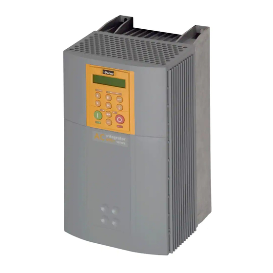
690+ Series
AC Drive
Frame G, H & J
Product Manual
HA465084U002 Issue 4
Compatible with Version 5.x Software
2010 Parker SSD Drives, a division of Parker Hannifin Ltd.
All rights strictly reserved. No part of this document may be stored in a retrieval system, or transmitted in any
form or by any means to persons not employed by a Parker SSD Drives company without written permission
from Parker SSD Drives, a division of Parker Hannifin Ltd . Although every effort has been taken to ensure the
accuracy of this document it may be necessary, without notice, to make amendments or correct omissions.
Parker SSD Drives cannot accept responsibility for damage, injury, or expenses resulting therefrom.
WARRANTY
Parker SSD Drives warrants the goods against defects in design, materials and workmanship for the period of
24 months from the date of manufacture, or 12 months from the date of delivery (whichever is the longer
period), on the terms detailed in Parker SSD Drives Standard Conditions of Sale IA500504.
Parker SSD Drives reserves the right to change the content and product specification without notice.
Advertisement
Table of Contents

Related Manuals for Parker 690 Plus Series


Summary of Contents for Parker 690 Plus Series
- Page 1 Parker SSD Drives company without written permission from Parker SSD Drives, a division of Parker Hannifin Ltd . Although every effort has been taken to ensure the accuracy of this document it may be necessary, without notice, to make amendments or correct omissions.
- Page 2 Parker or its subsidiaries or authorized distributors. To the extent that Parker or its subsidiaries or authorized...
- Page 3 Safety Information Requirements IMPORTANT: Please read this information BEFORE installing the equipment. Intended Users This manual is to be made available to all persons who are required to install, configure or service equipment described herein, or any other associated operation. The information given is intended to highlight safety issues, EMC considerations, and to enable the user to obtain maximum benefit from the equipment.
- Page 4 Safety Information Hazards DANGER! - Ignoring the following may result in injury 1. This equipment can endanger life by exposure to 5. For measurements use only a meter to IEC 61010 rotating machinery and high voltages. (CAT III or higher). Always begin using the highest range.
-
Page 5: Table Of Contents
Contents Contents Page HAPTER ETTING TARTED Introduction ....................1-1 Equipment Inspection ................... 1-1 Packaging and Lifting Details ..............1-1 About this Manual ..................1-1 Initial Steps ......................1-2 How the Manual is Organised .................1-2 HAPTER VERVIEW OF THE RIVE Component Identification ................2-1 Control Features ................... - Page 6 Using the Keypad to Manage Trips................6-2 Checksum Fail ......................6-5 Fault Finding....................6-5 HAPTER OUTINE AINTENANCE AND EPAIR Routine Maintenance..................7-1 Repair ......................7-1 Saving Your Application Data ..................7-1 Returning the Unit to Parker SSD Drives..............7-1 Disposal .........................7-1 Spares List ......................7-2 Component Replacement ..................7-3 Cont.6...
- Page 7 Contents Contents Page HAPTER ECHNICAL PECIFICATIONS Understanding the Product Code ..............8-1 690+ Model Recognition (Frame G) ................8-3 690+ Model Recognition (Frame H).................8-3 690+ Model Recognition (Frame J)................8-3 Environmental Details....................8-4 Earthing/Safety Details ....................8-4 Cabling Requirements for EMC Compliance .............8-5 Terminal Block Wire Sizes ..................8-5 Electrical Ratings (Frame G) ..................8-6 Electrical Ratings (Frame H) ..................8-7 Electrical Ratings (Frame J) ..................8-8...
- Page 8 Contents Contents Page High Starting Torque .................. 10-4 Winder Applications ................... 10-4 Roll Diameter Calculation Accuracy................10-4 Basic Set-up Instruction..................10-6 Equations ......................10-7 4-Q Regen Control/Common DC Bus Applications ........10-10 Introduction ......................10-10 4-Q Active Front End...................10-11 Drive Set-up......................10-13 Macro 8 : 4Q Regen ...................10-14 Connection Diagram for Macro 8A Single Motor System ........10-14 A Single Motor System..................10-15 A Multi-Motor System ..................10-16...
-
Page 9: Chapter 1 Getting Started
Getting Started ETTING TARTED Chapter 1 Introduction The 690+ Series AC Drive is designed for speed control of standard 3-phase induction motors. These larger models are available in a range of ratings for constant torque and quadratic torque applications. This dual mode feature provides a cost effective solution to general industrial applications, as well as the control of pumps and fans. -
Page 10: Initial Steps
Getting Started Note: Please read all Safety Information before proceeding with the installation and operation of this unit. Enter the “Model Number” from the rating label into the table at the front of this manual. There is also a column for you to record your application’s parameter settings in the Parameter Specification Table in the Software Product Manual. -
Page 11: An Overview Of The Drive
An Overview of the Drive VERVIEW OF THE RIVE Chapter 2 Component Identification Brake Unit DBR Brake Resistor Connection Brake Resistor Connections Negative (-) DC Positive (+) DC Buss Connection Buss Connection PE/Ground PE/Ground Connection Connection Lifting eyes (*See Note 1) 690+ Lifting eyes (*See Note 1) Must be left turned in this direction... -
Page 12: Control Features
An Overview of the Drive Equipment Supplied The following equipment is supplied as standard with each product: 1) Frequency drive 2) Installation and Software Product manuals 3) Lifting eyes (4 off) 4) Exhaust duct and top vent assembly 5) Main cooling fan (Frame J only) Product Range Chassis Size Nominal Power... -
Page 13: Functional Overview
An Overview of the Drive Functional Overview 690+ AC Drives are microprocessor based 3-phase drives used to control the speed of standard 3-phase induction motors. An extensive range of configuration options are available to the user. A menu structure controlled using the man-machine interface (MMI) allows access to various options and adjustable parameters. - Page 14 This is a non-isolated RS232 serial link for communication with the keypad. Alternatively, a PC running Parker SSD Drives’ “DSE Lite” Windows-based configuration software (or some other suitable PC programming tool) can be used to graphically program and configure the drive.
-
Page 15: Installing The Drive
Installing the Drive NSTALLING THE RIVE Chapter 3 IMPORTANT: Read Chapter 9: “Certification for the Drive” before installing this unit. Mechanical Installation Handling the Drive Prepare a clear, flat surface to receive the drive before attempting to move it. Do not damage any terminal connections when putting the drive down. -
Page 16: Fitting The Top Vent And Gasket (690+ H & J)
Installing the Drive requirements. When mounting two or more 690+ units together, these clearances are additive. Ensure that the mounting surface is normally cool. Fitting the Top Vent and Gasket (690+ H & J) WARNING! This unit must be operated with either a brake unit or blanking plate fitted to the supplied outlet duct. -
Page 17: Installing The External Vent Kit (Frame G)
Installing the Drive Installing the External Vent Kit (Frame G) Parker SSD Drives Part Numbers: Frame G : LA465720U001 Refer to Drawing HG465731U003 Sheet 2 at the end of this Chapter for top panel and mounting plate hole positions. Upper Housing... -
Page 18: Mounting The Drive
Installing the Drive Mounting the Drive IMPORTANT: The 690+ drive must be securely mounted using all 10 off M8 mounting hole positions as detailed on HG465731U00. Refer to the drawings at the end of this chapter. It must be mounted inside a suitable cubicle, depending upon the required level of EMC compliance –... -
Page 19: Ac Line Choke
Rating Guidelines for AC Line Chokes Parker SSD Drives can supply the line chokes listed in Chapter 8: "Technical Specifications" - Line Chokes. If you wish to source your own line choke refer to the individual Electrical Rating tables in Chapter 8 for the relevant rms line currents. - Page 20 Installing the Drive 315A, 75μH Choke Outline Drawing for Frames G, H & J - Drawing No. SD12224 690+ Series AC Drive...
- Page 21 Installing the Drive 480A, 50μH Choke Outline Drawing for Frames G, H & J - Drawing No. SD12225 690+ Series AC Drive...
- Page 22 Installing the Drive 680A, 35μH Choke Outline Drawing for Frames G, H & J - Drawing No. SD12226 690+ Series AC Drive...
-
Page 23: Main Cooling Fan And Supply Requirements
Installing the Drive Main Cooling Fan and Supply Requirements The Frame G and H drives have an integral main cooling fan. However, the Frame J drive has a separate main cooling fan which must be fitted to the bottom panel of the enclosure as shown in at the end of this chapter, with the 4 off M6 nuts provided. -
Page 24: Power Wiring And Protective Earth (Pe) Connections
3-10 Installing the Drive Power Wiring and Protective Earth (PE) Connections Earth/Ground M10 bolt & washer for 690+ compression terminations SERIES M3/W D C D D C 4 Q 1 5 A S E Q R E F P R O G J O G M2/V WARNING... -
Page 25: Control Wiring Connections
3-11 Installing the Drive Control Wiring Connections All 690+ Series AC Drives have the same control wiring connections. Note: Use screened control cables to comply with EMC requirements. All screens terminated using a gland at the gland plate. 1. Feed the control cables into the drive through the metal gland plate and connect to the control terminals. -
Page 26: Optional Equipment
3-12 Installing the Drive Optional Equipment System Board Front View (with items removed) With this factory-fitted expansion board, the 690+ drive is suitable for high-end web processing and mini PLC replacement applications. The following features are provided: • Converts AIN1-4 in to high resolution (12-bit plus sign) non-isolated analog inputs •... - Page 27 To ensure compliance with the EMC Directive the overall cable screen should be connected to the encoder body and to the drive chassis. Recommended cable (pairs individually screened): Belden equivalent 8777 Parker SSD Drives Part Number CM052666 Differential Encoders System Board Terminal B System Board Terminal D...
- Page 28 3-14 Installing the Drive Technology Options (Master drive only). Remote Operator Station Comms Speed Option Feedback Option WARNING! Isolate the drive before fitting or removing the option. There are two Technology Options: 1. Speed Feedback 2. Communications These are plugged into the two positions, as illustrated above. All Technology Options are designed as plug-in technology boxes.
- Page 29 3-15 Installing the Drive Fitting the Remote 6901/6911 Keypad The 6052 Mounting Kit is required to remote-mount a 6901/6911 Keypad. It is possible to: • Remote-mount the drive-mounted Keypad using the port(s) illustrated • Remote-mount an additional Keypad in the lower port (not Frame B) - in this case, both Keypads are fully functional •...
- Page 30 3-16 Installing the Drive Drive Brake Unit Refer to Chapter 8: "Technical Specifications" - Internal Dynamic Brake Switch for further Note: details. The brake unit is optional. However, it is possible to retro-fit a brake unit should the need arise. There are three brake units, one for each drive frame size.
- Page 31 3-17 Installing the Drive Required tools • M10 spanner • #3 posidrive or phillips torque screwdriver • #2 posidrive or phillips torque screwdriver Installation Procedure WARNING! Follow the procedure carefully. Disconnect all electrical supplies before working on the drive - allow 15 minutes for the drive dc link capacitors to fully discharge.
- Page 32 3-18 Installing the Drive SNUBBER CAPACITORS BULKHEAD CONNECTOR CONNECTING PLATE Figure 3-5 Front View of Exhaust Duct/Brake Unit/Drive Assembly showing the Brake Connecting Plate and Snubber Capacitors fitted External AC Supply EMC Filter WARNING! The specified external filters are only suitable for use with TN supplies. Please check for suitability in Chapter 8: “Technical Specifications”...
- Page 33 3-19 Installing the Drive Caution The filter flying leads may reach 100 C under normal operating conditions. These should be separated by at least one cable diameter and adequately ventilated. The connection between the drive module and the motor must be installed away from all other cables or wires.
- Page 34 3-20 Installing the Drive 100mm x 420mm DEEP 690+ SERIES 625 mm D C D D C 4 Q 1 5 A S E Q R E F P R O G J O G WARNING AVERTISSEMENT AC LINE CHOKE FITTED BETWEEN FILTER &...
- Page 35 3-21 Installing the Drive 100 mm x 420 mm DEEP 690+ SERIES D C D D C 4 Q 1 5 A S E Q R E F P R O G J O G 625 mm WARNING AVERTISSEMENT Min. Separation 40 mm LINE CHOKE FITTED BETWEEN FILTER &...
- Page 36 This can help the drive achieve EMC and filter thermal conformance. It also ensures longer motor life by reducing the high voltage slew rate and overvoltage stresses. Mount the filter as close to the VSD as possible. Please refer to Parker SSD Drives for the selection of a suitable filter.
-
Page 37: Installation Drawings
3-23 Installing the Drive Installation Drawings The 690+ drive must be securely mounted using all 10 off M8 mounting hole positions as shown. Frame G Typical Cubicle Installation Outline Drawing (HG465731U003 Sheet 1) 690+ Series AC Drive... - Page 38 3-24 Installing the Drive Frame G Typical Cubicle Machining (HG465731U003 Sheet 2) 690+ Series AC Drive...
- Page 39 3-25 Installing the Drive The 690+ drive must be securely mounted using all 10 off M8 mounting hole positions as shown. Frame H Typical Cubicle Installation Outline Drawing (HG465731U002 Sheet 1) 690+ Series AC Drive...
- Page 40 3-26 Installing the Drive Frame H Typical Cubicle Machining (HG465731U002 Sheet 2) 690+ Series AC Drive...
- Page 41 3-27 Installing the Drive The 690+ drive must be securely mounted using all 10 off M8 mounting hole positions as shown. Frame J Typical Cubicle Installation Outline Drawing (HG465731U001 Sheet 1) 690+ Series AC Drive...
- Page 42 3-28 Installing the Drive Frame J Typical Cubicle Machining (HG465731U001 Sheet 2) 690+ Series AC Drive...
-
Page 43: Operating The Drive
Operating the Drive PERATING THE RIVE Chapter 4 By default, the drive will operate in Remote Start/Stop and Remote Speed Control. Analog and DEFAULT digital inputs and outputs are selected to control the unit. The drive will operate as an open-loop drive. No set-up or tuning is required. It is programmed to control an induction motor of equivalent power, current and voltage rating to the drive. -
Page 44: Control Philosophy
Operating the Drive Control Philosophy There are four ways to control the drive using Remote and Local control: 690+ inverter 690+ inverter 690+ inverter 690+ inverter using using using using analog Technology and digital inputs and to fieldbus Operator outputs PC running Station Comms link... - Page 45 Operating the Drive Note: Start/Stop is also known as “Sequencing”. Speed Control is also known as “Reference Generation”. Selecting Local or Remote Control If the default combination of remote Start/Stop and Speed Control is not suitable for your application, follow the instructions below using the keypad or a suitable PC programming tool to select suitable combinations of local or remote control.
-
Page 46: Initial Start-Up Routines
Operating the Drive Initial Start-up Routines WARNING! Unpredictable motion, especially if motor parameters are incorrect. Ensure no personnel are in the vicinity of the motor or any connected machinery. Ensure that no machinery connected to the motor will be damaged by unpredictable motion. -
Page 47: Routine 2: Local Control Using The Keypad
Operating the Drive HEALTH Drive State Re-configuration, or corrupted non-volatile memory at power-up Tripped Auto Restarting, waiting for trip cause to clear Auto Restarting, timing Stopped Running with zero reference, enable false or contactor feedback false Running Stopping Braking and running with zero speed demand Braking and running Braking and stopping Table Chapter 4 -1 Status indications given by the Blank Cover Health and Run LEDs... - Page 48 Operating the Drive Set-up as an Open-loop Drive (V/F Fluxing) The parameters from the QUICK SETUP menu most likely to require MMI Menu Map attention in this control mode (VOLTS / HZ) are shown below. QUICK SETUP QUICK SET-UP Default Brief Description Parameters 1105 CONTROL MODE...
-
Page 49: The Autotune Feature
Operating the Drive Set-up using the Closed-loop Vector Mode WARNING! When the drive is run for the first time the direction of rotation will be unknown, the drive may run inconsistently, and the speed control may not operate. In this mode, speed feedback signals from the motor shaft encoder are MMI Menu Map processed to determine the rotational speed of the shaft. - Page 50 Operating the Drive Parameter Description Note LEAKAGE INDUC Per phase stator leakage inductance MUTUAL INDUC Per phase mutual inductance ROTOR TIME CONST Rotor time constant This is identified from magnetising current and motor nameplate rpm For further information on the functions of all parameters, refer to the Software Product Manual, Chapter 1: “Programming your Application”.
- Page 51 Operating the Drive IMPORTANT: Now perform a SAVE CONFIG to save your new settings. Refer to Chapter 5: “The Keypad” - Quick Save Feature. Performing a Stationary Autotune Before starting the stationary Autotune, you MUST enter the value of magnetising current for the motor.
-
Page 52: The Start/Stop Mode Explained
4-10 Operating the Drive The Start/Stop Mode Explained The default configuration below shows the drive in Remote control, (using the analog and digital inputs and outputs). This example will be referred to in the following explanations. SETPOINT SPEED SETPOINT Analog Input 1 Terminal 2 ACCEL TIME MAX SPEED CLAMP... -
Page 53: Starting And Stopping Methods
4-11 Operating the Drive Start/Stop Controlled Locally The reference value is set by the SETPOINT (LOCAL) parameter. The direction of rotation is controlled by the DIR key (forward/reverse) on the keypad. When the RUN key is pressed the SPEED DEMAND ramps up to the reference value at a rate controlled by ACCEL TIME. The drive will continue to run at the reference value even when the RUN key is released. - Page 54 4-12 Operating the Drive Ramp to Stop When a stop command is received, the drive decelerates from its actual speed towards zero for the programmed DECEL TIME time. When this time has elapsed, SPEED TRIM is ramped to 0% in the programmed STOP TIME time. Note: If SPEED TRIM does not operate, SPEED DEMAND is reduced to 0% in DECEL TIME.
-
Page 55: Advanced Stopping Methods
4-13 Operating the Drive Advanced Stopping Methods The drive can be selected to NOT FAST STOP or to NOT COAST STOP. The stopping procedure is unaffected by Local or Remote Sequencing options. Forced Fast Stop The Not Fast Stop mode overrides the RUN FWD, RUN REV and JOG inputs in Remote mode, and the RUN and JOG keypad keys in Local mode. -
Page 56: Starting Methods
4-14 Operating the Drive Logic Stopping The drive can be stopped by setting the NOT STOP to FALSE for a short time, (>100 ms). The stop sequence continues even if the NOT STOP signal goes inactive before the drive is stopped. Various combinations of stop logic are shown below. - Page 57 4-15 Operating the Drive The methods below can be used when the drive has Macro 1, 2, 3 or 4 installed. The default configuration view above caters for Single, Two, and Three Wire Logic Starting DEFAULT without rewiring. Note that the NOT STOP parameter is active (FALSE - not wired to), meaning that the drive will only run while the relevant RUN parameters are held TRUE.
- Page 58 4-16 Operating the Drive 690+ Series AC Drive...
-
Page 59: The Keypad
The Keypad EYPAD Chapter 5 Connecting the Keypad The Keypad is a plug-in MMI (Man-Machine Interface) option that allows full use of the drive’s features. I IT G AL DC D I V OTOR D I V It provides for local control of DC 4Q 15A 0.75kW 230V... -
Page 60: Controlling The Drive Using The Keypad
The Keypad Controlling the Drive using the Keypad Control Key Definitions Note: Refer to Chapter 4: “Operating the Drive” for more detail about Remote and Local modes. Keys for Programming the Drive Note: See “Navigating the Menu System”, page 5-4 for a quick-start to using the menu. Navigation - Moves upwards through the list of parameters. -
Page 61: Led Indications
The Keypad LED Indications There are seven LEDs that indicate the status of the drive. Each LED is considered to operate in three different ways: The LEDs are labelled HEALTH, LOCAL (as SEQ and REF), FWD, REV, RUN, and STOP. FLASH Combinations of these LEDs have the following meanings:... -
Page 62: The Menu System
The Keypad The Menu System The menu system is divided into a `tree’ structure with 5 The Menu System menu levels. Menu Level 1 is at the top of the tree. WELCOME SCREEN The Keypad has selectable “viewing levels” which can restrict the view of the menu system. -
Page 63: Changing A Parameter Value
The Keypad Changing a Parameter Value Refer to “The Menu System Map to see how the increment full menu is mapped. Each menu contains parameters. exit enter With the Parameter you want on view, press M to parameter parameter begin editing. change change The up ( ) and down ( ) keys will now change the... -
Page 64: The Menu System Map
The Keypad The Menu System Map MENU LEVEL 4 MENU LEVEL 1 MENU LEVEL 2 MENU LEVEL 3 OPERATOR menu at level 1 DIAGNOSTICS menu at level 1 QUICK SETUP menu at level 1 SETUP COMMUNICATIONS 5703 INPUT menu at level 1 5703 OUTPUT SYSTEM SYSTEM PORT (P3) - Page 65 The Keypad MENU LEVEL 4 MENU LEVEL 1 MENU LEVEL 2 MENU LEVEL 3 AUTOTUNE MOTOR CONTROL CURRENT LIMIT DYNAMIC BRAKING FEEDBACKS FLUXING FLYCATCHING INJ BRAKING INVERSE TIME MOTOR DATA PATTERN GEN POWER LOSS CNTRL SETPOINT SCALE SLEW RATE LIMIT SLIP COMP SPEED LOOP STABILISATION...
-
Page 66: The Prog Key
The Keypad The PROG Key The PROG key toggles between the OPERATOR menu and any other menu, remembering and returning to previous positions in each menu. As you press the PROG key, the title of the menu you are about to enter is displayed, i.e. OPERATOR or for example DIAGNOSTICS. Releasing the key clears the display and releases you into that menu. -
Page 67: The Operator Menu
The Keypad The OPERATOR Menu You can create 16 “custom screens” for display in the OPERATOR MMI Menu Map menu at level 1. OPERATOR Each screen contains: • a top line of sixteen characters • user-definable units • user-selectable scaling factor •... -
Page 68: String Entry
5-10 The Keypad String Entry Customising the Parameter Name To enter a string: • Press the M key to begin entering a character. • Use the ( ) and down ( ) keys to scroll through the character set for each of the character spaces. -
Page 69: The Diagnostics Menu
5-11 The Keypad The DIAGNOSTICS Menu Diagnostics are used to monitor the status of the drive, internal MMI Menu Map variables, and its inputs and outputs. DIAGNOSTICS The table below describes the parameters contained in the DIAGNOSTICS menu at level 1. Ranges are given as “—.xx %”, for example, indicating an indeterminate integer for the value. - Page 70 5-12 The Keypad The DIAGNOSTICS Menu DIRECT INPUT Tag No. 1205 Range: —.xx % The value of the direct input, after scaling and clamping. (Refer to the SPEED LOOP function block) TORQ DMD ISOLATE Tag No. 1202 Range: FALSE / TRUE Speed Control mode and Torque Control mode selection.
- Page 71 5-13 The Keypad The DIAGNOSTICS Menu ACTIVE TRIPS Tag No. 4 Range: 0000 to FFFF Indicates which trips are currently active. These parameters are a coded representation of the trip status. (Refer to the TRIPS STATUS function block) ACTIVE TRIPS + Tag No.
- Page 72 5-14 The Keypad The DIAGNOSTICS Menu DIGITAL INPUT 7 Tag No. 728 Range: FALSE / TRUE (VALUE) The TRUE or FALSE input, (after any inversion). (Refer to the DIGITAL INPUT function block) EXTERNAL TRIP Tag No. 234 Range: FALSE / TRUE (EXTERNAL) A general purpose signal designed to be internally wired to a digital input block.
-
Page 73: The Quick Setup Menu
5-15 The Keypad The QUICK SETUP Menu By loading a different macro, you are installing the default settings for MMI Menu Map that macro’s application. Once a macro has been loaded (or the default QUICK SETUP Macro 1 is used), the parameters most likely to require attention are contained in the QUICK SETUP menu at level 1. -
Page 74: The System Menu
5-16 The Keypad The SYSTEM Menu Saving/Restoring/Deleting Your Application Caution On power-up, the drive will always run APPLICATION. HINT: The default APPLICATION supplied with the drive is a copy of Macro 1. Saving your current configuration to APPLICATION will ensure that it is always ready to run on power-up. SAVE CONFIG The SAVE CONFIG menu saves your current settings to the MMI Menu Map... - Page 75 5-17 The Keypad NEW CONFIG NAME MMI Menu Map Use the NEW CONFIG NAME parameter to create a new config name. SYSTEM The Keypad provides a default name, APPLICATION, for you to save NEW CONFIG NAME your application in. You can save more than one application using NEW CONFIG NAME different names, e.g.
-
Page 76: Selecting The Language
5-18 The Keypad Selecting the Language This option selects a different display language. MMI Menu Map SYSTEM LANGUAGE LANGUAGE ENGLISH LANGUAGE LANGUAGE ENGLISH LANGUAGE other language other The available languages are: ENGLISH, GERMAN, FRENCH, SPANISH, ITALIAN, SWEDISH, POLISH, PORTUGUESE. Special Menu Features Quick Save Feature From anywhere in the menu system, hold down the PROG key for approximately 3 seconds to move quickly to the SAVE CONFIG menu. -
Page 77: Quick Tag Information
5-19 The Keypad Quick Tag Information With a parameter displayed, hold down the M key for approximately 3 seconds to display the parameter’s tag number (a message may be displayed during this time). RAMP TIME 100.00% HOLD FOR 3 SECONDS RAMP TIME RAMP TIME 100.00%... -
Page 78: Password Protection
5-20 The Keypad Password Protection MMI Menu Map When activated, the password prevents unauthorised parameter modification by making all parameters “read-only”. If you attempt to SETUP modify a password protected parameter, you will be prompted for the MENUS password. ACCESS CONTROL The password protection is activated/deactivated using the PASSWORD PASSWORD parameter. -
Page 79: Power-Up Key Combinations
Select from the expanded SYSTEM menu DELETE CONFIG IMPORTANT: We recommend the menus marked *above are only used by Parker SSD Drives or suitably qualified personnel. Refer to The SYSTEM Menu, page 5-16 for all non-highlighted menus. 690+ Series AC Drive... -
Page 80: Quick Enter Configuration Mode
5-22 The Keypad POWER BOARD HOLD Hold down the keys opposite: PROG Power-up the drive, continue to hold for at least 2 seconds POWER DATA Config mode is selected, CORRUPT indicated by all LEDs flashing POWER BOARD ????kW POWER BOARD ????kW POWER BOARD 5.5kW 400V... -
Page 81: Trips And Fault Finding
Trips and Fault Finding RIPS AND AULT INDING Chapter 6 Trips What Happens when a Trip Occurs When a trip occurs, the drive’s power stage is immediately disabled causing the motor and load to coast to a stop. The trip is latched until action is taken to reset it. This ensures that trips due to transient conditions are captured and the drive is disabled, even when the original cause of the trip is no longer present Drive Indications... -
Page 82: Using The Keypad To Manage Trips
Trips and Fault Finding Using the Keypad to Manage Trips Trip Messages If the drive trips, then the display immediately shows a message indicating the reason for the trip. The possible trip messages are given in the table below. Trip Message and Meaning Possible Reason for Trip OVERVOLTAGE The drive internal dc link voltage is too... - Page 83 OVERSPEED Speed feedback > 150% for 0.1 seconds UNKNOWN An unknown trip - refer to Parker SSD Drives MAX SPEED LOW During Autotune the motor is required to run at the nameplate speed o f the motor. If MAX SPEED RPM limits the speed to less than this value, an error will be reported.
- Page 84 Trips and Fault Finding Trip Message and Meaning Possible Reason for Trip NOT AT SPEED The motor was unable to reach the required speed to carry out the Autotune. Possible reasons include: • motor shaft not free to turn • the motor data is incorrect MAG CURRENT FAIL It was not possible to find a suitable value of...
-
Page 85: Checksum Fail
If data will not save correctly, the keypad will display a failure message. In this case, the drive has developed a fault and must be returned to Parker SSD Drives. Refer to Chapter 7: “Routine Maintenance and Repair". Fault Finding... - Page 86 Trips and Fault Finding Troubleshooting LEDs In addition to the diagnostics provided by the keypad, eight fault LEDs situated on the power control board provide an indication of the cause of a fault trip. The fault LEDs are visible when the bottom terminal cover is removed - refer to Figure 1.1.
-
Page 87: Routine Maintenance And Repair
• Details of the fault Contact your nearest Parker SSD Drives Service Centre to arrange return of the item. You will be given a Returned Material Authorisation. Use this as a reference on all paperwork you return with the faulty item. Pack and despatch the item in the original packing materials; or at least an anti-static enclosure. -
Page 88: Spares List
Routine Maintenance and Repair Spares List Parker SSD Drives are able to provide guidance regarding the necessary component part to be replaced. The serviceable component parts are listed below. Electro-Mechanical Parts The selection of the following items are product/kW rating dependant. -
Page 89: Component Replacement
Routine Maintenance and Repair Component Replacement Having identified the faulty component part and taken delivery of replacement part(s) the following replacement procedure should be carefully adhered to. WARNING! FAILURE TO FOLLOW PROCEDURE MAY RESULT IN DAMAGE TO THE DRIVE AND POSSIBLE ELECTRICAL SHOCK HAZARD! PERSONNEL PERFORMING COMPONENT REPLACEMENT PROCEDURES MUST BE ELECTRICALLY COMPETENT AND POSSESS THE KNOWLEDGE /EXPERTISE REQUIRED TO PERFORM THE RELEVANT OPERATION... - Page 90 Routine Maintenance and Repair 1. Remove drive top and bottom terminal cover (plastic) via 2 off ¼ turn fasteners at top and bottom of drive. 2. Disconnect 4-way op-station cable from LED PCB. 3. Remove drive front cover (metal) which is attached via 4 off ¼ turn fasteners (take care not to damage PCBs beneath cover).
- Page 91 Routine Maintenance and Repair Line Suppression AH389192 PCB Replacement Remove drive top and bottom terminal cover (plastic) via 2 off ¼ turn fasteners at top and bottom of drive. Disconnect 4-way op-station cable from LED PCB (see figure 7.1). Remove drive front cover (metal) which is attached via 4 off ¼ turn fasteners (take care not to damage PCBs beneath cover).
- Page 92 Routine Maintenance and Repair Frames G & H Drive Main Cooling Fan and Fan Start Capacitor Replacement Remove drive top and bottom terminal cover (plastic) via 2 off ¼ turn fasteners at top and bottom of drive. Disconnect 4-way op-station cable from LED PCB (see figure 7.1). Remove drive front cover (metal) which is attached via 4 off ¼...
- Page 93 Routine Maintenance and Repair J. W . F . SCALE THIRD ANGLE PROJECTION GENERAL DRAWING PRACTICE BS 308 / BS 3939 DATE 25/06/96 2 OFF 120mm SQ 28/06/96 115V AC FAN 15/07/96 25/07/96 06/03/97 23/05/97 THROUGH PANEL 115V MOUNT TERMINAL VERSION BLOCKS EARTH...
- Page 94 Routine Maintenance and Repair Phase Assembly Replacement The drive power stage consists of 3 identical phase assemblies. Each phase assembly consists of heatsink, IGBT module plus gate drive pcb, 1/3 of the input bridge, DC link capacitors and PCB ‘AH389193’. It is intended that the whole phase assembly be carried as a spare part and replaced as a unit.
- Page 95 Routine Maintenance and Repair Phase Assembly Replacement Procedure Replace any badly distorted heatsink clamps with spare clamps provided. (Clamps used in packaging). Carefully slide replacement phase limb assembly into position making sure that the studs on the input busbars (left-hand side) located in the holes provided on the phase limb busbar.
- Page 96 7-10 Routine Maintenance and Repair BRAKE LINK PLATE DC +ve BUSBAR DC -ve BUSBAR DC -ve DC +ve HEATSINK MOUNTING CLAMP Output current Sensor * EARTH BONDING WIRE INSULATING CAPS OUTLINE OF CAPACITOR JOINING PHASE LIMB PLATES Output current Sensor * SERVICE PLATE CONTROL PCB SUPPORT PANEL...
-
Page 97: Chapter 8 Technical Specifications
Technical Specifications ECHNICAL PECIFICATIONS Chapter 8 Understanding the Product Code Manufacturing Product Codes The unit is fully identified using an alphanumeric code which records how the drive was calibrated, and its various settings when dispatched from the factory. The Product Code appears as the “Model No.”. Each block of the Product Code is identified as below: AC690+ (400/460V) Integrator Series Frame G, H &... - Page 98 Technical Specifications US Model Number & Legacy Product Codes Catalog Number (North America) The unit is identified using a 6 block alphanumeric code which records how the drive was calibrated, and its various settings when dispatched from the factory. The Product Code appears as the “Cat No.”. Each block of the Product Code is identified as below: Typical example: 690+/0200/460/1BN...
-
Page 99: Model Recognition (Frame G)
Technical Specifications 690+ Model Recognition (Frame G) The 690+G drive is produced in four power ratings, identified by the Product Code. 380-460V Supply Model Recognition CONSTANT TORQUE QUADRATIC TORQUE Motor Power Motor Power Model Number (Europe) Catalog Number (North America) (kW/hp) (kW/hp) 690-433216... -
Page 100: Environmental Details
Technical Specifications Environmental Details Operating Temperature Operating temperature is defined as the ambient temperature to the immediate surround of the drive, when the drive and other equipment adjacent to it is operating at worst case conditions. 0°C to 40°C, derate up to a maximum of 50°C Constant Torque 0°C to 40°, derate up to a maximum of 50°C Quadratic Torque... -
Page 101: Cabling Requirements For Emc Compliance
Technical Specifications Cabling Requirements for EMC Compliance Power Supply Motor Cable External AC Brake Signal/Control Cable Cable Supply EMC Resistor Filter to Drive Cable Cable Cable Type Unscreened Screened/ Screened/ Screened/ Screened armoured armoured armoured (for EMC Compliance) Segregation From all From all other wiring (noisy) From all other wiring other wiring... -
Page 102: Electrical Ratings (Frame G)
Technical Specifications Electrical Ratings (Frame G) Motor power, output current and input current must not be exceeded under steady state operating conditions. NOTES: 1. IMPORTANT : 3% line impedance MUST be provided for each unit, and is assumed in the quoted input current values. Failure to do so will severely shorten DC link capacitor lifetime and could result in damage to the bridge. -
Page 103: Electrical Ratings (Frame H)
Technical Specifications Electrical Ratings (Frame H) Motor power, output current and input current must not be exceeded under steady state operating conditions. NOTES: 1. IMPORTANT : 3% line impedance MUST be provided for each unit, and is assumed in the quoted input current values. Failure to do so will severely shorten DC link capacitor lifetime and could result in damage to the bridge. -
Page 104: Electrical Ratings (Frame J)
Technical Specifications Electrical Ratings (Frame J) Motor power, output current and input current must not be exceeded under steady state operating conditions. NOTES: 1. IMPORTANT : 3% line impedance MUST be provided for each unit, and is assumed in the quoted input current values. Failure to do so will severely shorten DC link capacitor lifetime and could result in damage to the input bridge. -
Page 105: External Ac Supply (Rfi) Filter (Part Number Co467843U340)
Failure to provide the correct line impedance will severely reduce the drives lifetime and could result in catastrophic failure of the drive. The required AC Line Choke line impedance is nominally 3% of the drive rating. Parker SSD Drives can supply the following ac line chokes: Frame Constant/Quadratic... -
Page 106: Internal Dynamic Brake Switch (Frame G)
8-10 Technical Specifications Internal Dynamic Brake Switch (Frame G) Motor Brake Switch Peak Brake Brake Switch Continuous Brake Minimum Power Peak Current Dissipation Continuous Dissipation Brake Resistor (kW) (kW/hp) Current (kW/hp) Value (Ω) 380-460V ±10%, 45-65Hz DC link brake voltage: 750 - 820V 20s maximum, 30% duty 270/360 54/72... -
Page 107: Control Terminals
8-11 Technical Specifications Control Terminals Terminal Name Range Description (Default functions are for Macro 1) ANALOG I/O TERMINAL BLOCK This is a 10-way connector carrying all customer analog I/O. 0V reference for analog i/o AIN1 (SPEED) 0-10V, ±10V, 0-20V Configurable analog input Default function = Speed Setpoint 0-20mA, 4-20mA AIN2 (TRIM) -
Page 108: System Board Terminals (Option)
8-12 Technical Specifications System Board Terminals (option) Terminal Name Range Description (Default functions are for Macro 1) Terminal A 1 2 3 4 5 6 External 0V User-supplied 0V reference DIGIO11 Configurable digital input/output DIGIO12 Configurable digital input/output DIGIO13 Configurable digital input/output DIGIO14 Configurable digital input/output DIGIO15... -
Page 109: Analog Inputs/Outputs
8-13 Technical Specifications Analog Inputs/Outputs Inputs Output Range 0-10V, ±10V, 0-20mA or 4-20mA 0-10V, 0-20mA or 4-20mA (range set in software) (range set in software) Impedance Voltage range = 47kΩ Voltage range = 100Ω Current range = 220Ω Recommended Load - 220Ω Resolution 10 bits (1 in 1024) 10 bits (1 in 1024) -
Page 110: Supply Harmonic Analysis (Frame G Quadratic)
8-14 Technical Specifications Supply Harmonic Analysis (Frame G Quadratic) The results conform to stage 2 and stage 3 of the Engineering Recommendation ∑ Q G.5/3 September 1976, Classification ‘C’: Limits for Harmonics in the UK THD(V) x 100 = h 40 Electricity Industry. -
Page 111: Supply Harmonic Analysis (Frame H Quadratic)
8-15 Technical Specifications Supply Harmonic Analysis (Frame H Quadratic) The results conform to stage 2 and stage 3 of the Engineering Recommendation ∑ Q G.5/3 September 1976, Classification ‘C’: Limits for Harmonics in the UK THD(V) x 100 = h 40 Electricity Industry. -
Page 112: Supply Harmonic Analysis (Frame J Quadratic)
8-16 Technical Specifications Supply Harmonic Analysis (Frame J Quadratic) The results conform to stage 2 and stage 3 of the Engineering Recommendation ∑ Q G.5/3 September 1976, Classification ‘C’: Limits for Harmonics in the UK THD(V) x 100 = h 40 Electricity Industry. -
Page 113: Certification For The Drive
Certification for the Drive ERTIFICATION FOR THE RIVE Chapter 9 Requirements for EMC Compliance All Variable Speed Drives (VSDs) potentially produce electrical emissions which are radiated into the environment and conducted back into the ac supply. VSDs are inherently immune to any additional external electrical noise. -
Page 114: Cabling Requirements
Certification for the Drive Control and signal cables for the encoder, all analog inputs, and communications require screening with the screen connected only at the VSD end. However, if high frequency noise is still a problem, earth screen at the non VSD end via a 0.1μF capacitor. Note: Connect the screen (at the VSD end) to the VSD protective earth point, and not to the control board terminals. -
Page 115: Emc Installation Options
Certification for the Drive EMC Installation Options The unit, when installed for Class A or Class B operation, will be compliant with EN55011/ EN55022 for radiated emissions, as described below. Screening & Earthing (cubicle mounted, Class B) Note: The installation requirements of local safety standards must be achieved regarding the safety of electrical equipment for machines.. - Page 116 Certification for the Drive 2 Dirty Earth Busbar (insulated from the mounting panel) Used for all power earths, i.e. protective earth connection. It is also used as a reference for any 110 or 220V control used, and for the control transformer screen. 3 Metal Work Earth Busbar The back panel is used as this earth busbar, and should provide earthing points for all parts of the cubicle including panels and doors.
-
Page 117: Requirements For Ul Compliance
Certification for the Drive • DC link connections (even when screened/armoured) • Relays and contactors (even when suppressed) From experience, the following equipment is particularly sensitive and requires careful installation. • Any transducers which produce low level analog outputs (<1V) , e.g. load cells, strain gauges, thermocouples, piezoelectric transducers, anemometers, LVDTs •... - Page 118 Certification for the Drive Recommended Wire Sizes North American wire sizes are based on NEC/NFPA-70 for ampacities of thermoplastic- insulated (75ºC) copper conductors assuming not more than three current-carrying conductors in raceway or cable, based on ambient temperature of 30ºC. The wire sizes allow for an ampacity of 125% of the rated input and output amperes for motor branch-circuit conductors as specified in NEC/NFPA-70.
- Page 119 Certification for the Drive Field Grounding Terminals The field grounding terminals are identified with the International Grounding Symbol (IEC Publication 417, Symbol 5019). Operating Ambient Temperature All units are considered acceptable for use in a maximum ambient temperature of 40°C. UL Terminations UL compression Terminal Lug Kits are available for the drives which provide sets of lugs suitable for the following ratings.
-
Page 120: European Directives And The Ce Mark
EMC Directive. CE Marking for Low Voltage Directive When installed in accordance with this manual, the drive is CE marked by Parker SSD Drives in accordance with the low voltage directive (S.I. No. 3260 implements this LVD directive into UK law). -
Page 121: Which Standards Apply
It is important that you have now defined who is responsible for conforming to the EMC directive, either: Parker SSD Drives Responsibility You intend to use the unit as relevant apparatus. When the specified EMC filter is correctly fitted to the unit following EMC installation instructions, it complies with the relevant standards indicated in the following tables. -
Page 122: Certificates
Dr Martin Payn ( Conformance Officer) * Compliant with the immunity requirements of the Standard without specified EMC filters. PARKER HANNIFIN LTD, AUTOMATION GROUP, SSD DRIVES EUROPE, NEW COURTWICK LANE, LITTLEHAMPTON, WEST SUSSEX BN17 7RZ TELEPHONE: +44(0)1903 737000 FAX: +44(0)1903 737100 Registered Number: 4806503 England. -
Page 123: Application Notes
Application advice is available through our Technical Support Department, who can also arrange for on-site assistance if required. Refer to the back cover of this manual for the address of your local Parker SSD Drives Company. • Always use gold flash relays, or others designed for low current operation (5mA), on all control wiring. -
Page 124: Using Line Chokes
10-2 Application Notes Using Line Chokes Line chokes are required to limit input current to these Parker SSD Drives drives. Using Output Contactors The use of output contactors is permitted. It is recommended that this type of operation be limited to emergency use only or in a system where the drive can be inhibited before closing or opening this contactor. -
Page 125: Using Multiple Motors On A Single Drive
10-3 Application Notes Using Multiple Motors on a Single Drive A single large drive can be used to supply several smaller motors provided that each individual motor has overload protection. Note: Conventional V/F control strategy must be enabled for use with parallel motors. (Sensorless vector control strategy cannot be used). -
Page 126: High Starting Torque
10-4 Application Notes The Dynamic Braking Option is a PCB with an extra IGBT power device fitted. It is fitted inside the drive package and is connected to the negative side of the dc link. When the dc link voltage rises above that specified for each Frame size (Chapter 8: “Technical Specifications”... - Page 127 10-5 Application Notes Ultrasonic sensor Drive Drive +10V Initial diameter potentiometer +24V +24V Line zero Set diameter speed pushbutton relay Figure 10-3 Roll Diameter The left hand diagram above shows a simple, low accuracy way of pre-setting the roll diameter. Here, a potentiometer is used by the machine operator to set the roll diameter.
-
Page 128: Basic Set-Up Instruction
10-6 Application Notes Web must NEVER slip on Reel Drive must these line reference rolls NEVER slip Reel speed Line Speed Calculated diameter Diameter Calculated reel speed Calc. reference before PID trim default Winder Line Ramp Speed Reference Calc alternative Figure 10-4 Line Reference and Line Speed By default, Line Speed is connected to ANIN 1 and is used both as Line Reference and Line Speed. -
Page 129: Equations
10-7 Application Notes Set-up with no Web connected to the Winder The majority of the drive set-up should be performed without web connected to the centre winder. This allows the winding spindle to rotate freely, without being restrained by the web. Before configuring the Closed Loop centre winder load the Winder macro, refer to the Software Product Manual, Chapter 5: “Application Macros”. - Page 130 10-8 Application Notes Metric Units The following SI units are used to produce the equations shown below. Tension - Kilograms force (kgf) Torque - Newton Metres (Nm) Line Speed - Metres/Sec (MS-1) Line accel - Metres/Sec2 (MS-2) Rotation speed - RPM (RPM) Roll Diameter - Metres (M) Power - KWatt (kW) Mass - kg (kg)
- Page 131 10-9 Application Notes Motor Torque The worst case motor torque will exist for the following conditions:- Maximum roll diameter Maximum acceleration rate Maximum roll width Maximum material tension Maximum roll mass × × 4 905 Torque Tension Roll Diameter Tension Assuming the roll is a solid cylinder ×...
-
Page 132: 4-Q Regen Control/Common Dc Bus Applications
10-10 Application Notes 4-Q Regen Control/Common DC Bus Applications Introduction A 4-Q REGEN (4 Quadrant Regenerative) control mode is available on all 690+ Series AC Drives that : ♦ use Software Version 5.1 or greater ♦ display “/007” in Block 12 of the (Europe) Product Code, indicating that Special Option 7 is applied (“Y”... -
Page 133: 4-Q Active Front End
10-11 Application Notes 4-Q Active Front End The 4-Q Regen drive requires the following 4-Q Active Front End: Notes: Contactor CON1 is rated to match the 4-Q power supply drive current (AC1 rating) The 3% and 5% line chokes are custom designed for this application. Refer to page 10-10-20 The 4-Q Active Front End connects to the U, V, W terminals on the 4Q-Regen Drive. - Page 134 10-12 Application Notes EMC Filtering We recommend all 690+ Regen systems meet the EMC product specific standard EN61800- 3:1997. To achieve this, an EMC filter is required. Refer to Chapter 8 for details of suitable filters. Contactor and Fusing ♦ Use AC Line Fuses to protect the 4-Q Regen drive. These fast, semiconductor protection fuses must be capable of withstanding the system AC supply voltage.
-
Page 135: Drive Set-Up
10-13 Application Notes Drive Set-up The 690+ drive must be set-up Regen Control correctly to work in a 4-Q Regen – SYNCHRONIZING [1641] – FALSE Control/Common DC Bus – SYNCHRONIZED [1642] – FALSE PHASE LOSS [1643] – FALSE – Application. –... -
Page 136: Macro 8 : 4Q Regen
10-14 Application Notes Macro 8 : 4Q Regen Macro 8 is provided to simplify the set-up of 4-Q Regen systems. A full description of Macro 8 can be found in the Software Product Manual, Chapter 5. To use Macro 8, set the CONTROL MODE parameter to "4-Q REGEN", and set the Note: LEAKAGE INDUC parameter to the value of the total line choke inductance (refer to page 10-21), as discussed in "Drive Set-up"... -
Page 137: A Single Motor System
10-15 Application Notes A Single Motor System Boosted Common DC Link Supply 690+ Drive 690+ Drive 4-Q Active Front End 720V Link Fuses (4-Q Power Supply) DC - DC - External Pre - Charge Control Motor Load AC Motor The simplest configuration for 4-Q Regen control is a single 690+ Regen drive acting as the unity power factor supply, connected via the DC link to another 690+ driving the application. -
Page 138: A Multi-Motor System
10-16 Application Notes A Multi-Motor System Boosted Common DC Link Supply 690+ Drive 4-Q Active Front End 720V (4-Q Power Supply) DC - DC Link Fuses External Pre - Charge Control DC - DC - 690+ 690+ Drive Drive AC Motor AC Motor Motor Acting as Brake Motor Acting as Load... -
Page 139: A Smart Brake System
10-17 Application Notes A Smart Brake System DC Link Healthy Common DC Link 690+ Drive 4-Q Active Front End (Smart Brake) DC - DC Link Isolating Contactor Transformer External Pre -Charge Control Link Fuses 3-Phase 3-Phase Line Choke Line Choke DC - DC - DC Link... -
Page 140: Dc Link Fuses
10-18 Application Notes DC Link Fuses Below is a list of parts for the DC Link Fuses. Refer to the Electrical Ratings tables for Quadratic Duty motor powers. Select the correct part for the drive's Motor Power. Motor Power Frame DC Fuse DC Fuse Fuse... -
Page 141: Pre-Charge Sizing
Refer to the Electrical Ratings tables for Constant Duty motor powers. We recommend that standard Parker SSD Dynamic Braking resistors are used for the external pre-charge circuit. The continuous and peak power capabilities of these resistors are given... -
Page 142: 3-Phase Choke Sizing
The PWM switching produces high levels of harmonic current in the 3% chokes. It is essential to have these properly rated to avoid significant overheating. Suitable chokes have been developed for Parker SSD Drives and their Part Numbers are provided below. 690+ Series AC Drive... - Page 143 10-21 Application Notes 3% Choke Motor Input Active Drive Choke Inductance Currents Power Voltage Front End Frame Size (kW/Hp) (μH) 50Hz 1kHz 2.5kHz LA468346U004 CO468341U004 14.95 0.39 0.00 7.5/10 LA468346U008 CO468341U011 25.38 0.66 0.00 18.5/25 LA468346U018 CO468341U018 61.63 1.59 0.00 22/30 LA468346U022 CO468341U030...
- Page 144 10-22 Application Notes 690+ Series AC Drive...
-
Page 145: Application Macros
11-1 The Default Application PPLICATION ACROS Chapter 11 The Default Application The drive is supplied with various macros. Each macro recalls a pre-programmed set of parameters when it is loaded. • Macro 1 is the factory default macro, providing for basic speed control Note: Refer to the Software Product Manual for details of other macros. - Page 146 11-2 The Default Application 690+ Series AC Drive...
-
Page 147: Macro 1: Basic Speed Control (Default)
11-3 The Default Application Value Func 1 Minimum Speed OUTPUT [133] – 0.00 % Skip Frequencies OUTPUT [335] – 0.00 % Reference Analog Input 1 Analog Output 1 (12) – VALUE [ 16] – 0.00 % 0.00 % – [130] INPUT A –... -
Page 148: Macro 1: Basic Speed Control (Default)
11-4 The Default Application Macro 1: Basic Speed Control (default) This macro provides standard control of the drive. Control Wiring I/O Terminal Name Purpose Comment ANALOG INPUT 1 Speed Setpoint 0V = 0%, 10V = 100% ANALOG INPUT 2 Speed Trim 0V = 0%, 10V = 100% ANALOG OUTPUT 1 Ramp Output...
Need help?
Do you have a question about the 690 Plus Series and is the answer not in the manual?
Questions and answers