
Related Manuals for Parker 6K2


Summary of Contents for Parker 6K2
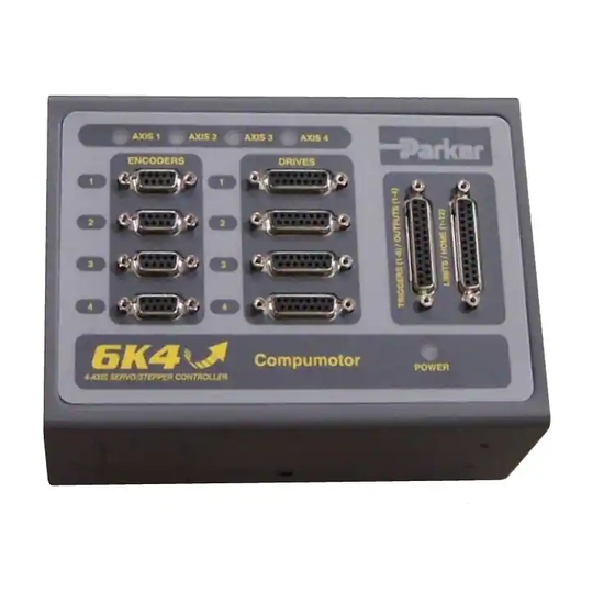
- Page 1 88-017547-01 A Automation 6K Series Hardware Installation Guide Effective: November 9, 1998 6K2 (2-axis Controller) 6K4 (4-axis Controller) 6K6 (6-axis Controller) 6K8 (8-axis Controller)
- Page 2 6K Series products and the information in this user guide are the proprietary property of Parker Hannifin Corporation or its licensers, and may not be copied, disclosed, or used for any purpose not expressly authorized by the owner thereof.
-
Page 3: Table Of Contents
• Ethernet or serial (RS-232 or RS-485) communication, depending on which communication protocol you are using. Related Publications • 6K Series Command Reference, Parker Hannifin Corporation, Compumotor Division; part number 88-017136-01 • 6K Series Programmer’s Guide, Parker Hannifin Corporation, Compumotor Division;... - Page 5 C H A P T E R O N E Installation IN THIS CHAPTER • Things to consider before you install your 6K controller ......2 • Product ship kit list..................3 • General specifications table ................4 • Dimensions and mounting guidelines............6 •...
-
Page 6: Chapter 1. Installation Before You Begin
%HIRUH#<RX#%HJLQ #####:$51,1*6##### The 6K controller is used to control your system’s electrical and mechanical components. Therefore, you should test your system for safety under all potential conditions. Failure to do so can result in damage to equipment and/or serious injury to personnel. ALWAYS REMOVE POWER TO THE 6K CONTROLLER BEFORE: •... -
Page 7: Series Controller Ship Kit
Optional Accessories Part Name Part Number Drive cable to Parker step & direction drives, 10-foot........71-016137-10 Drive cable to ± 10V drives, 10-foot (no connector at drive end)....71-017003-10 VM25 25-pin screw-terminal adapter for onboard I/O (with 2-foot cable) ..VM25 60 Watt power supply (DIN rail mountable) .......... -
Page 8: Series General Specifications
9.#6HULHV#*HQHUDO#6SHFLILFDWLRQV Parameter Specification Power (DC input) ..........24VDC ±10%, 2A max. (current requirements depend on type/amount of I/O used) Environmental Operating temperature ........32 to 122°F (0 to 50°C) Storage temperature ......... -22 to 185°F (-30 to 85°C) Humidity ............0 to 95% non-condensing Performance Command output .......... -
Page 9: Setup (Optional)
5607;8#6HWXS#+2SWLRQDO, READ THIS FIRST The “RS-232/485” connector (also referred to as “COM2”) is factory-configured for RS-232 communication; this makes it compatible with an RP240 remote operator panel. If you are not using RS-485 communication, skip this section and proceed to Mounting. CAUTIONS •... -
Page 10: Series Dimensions & Mounting
9.#6HULHV#'LPHQVLRQV#)#0RXQWLQJ Dimensions 6K2 & 6K4 6K6 & 6K8 6K Hardware Installation Guide... -
Page 11: Mounting
Mounting Environmental Considerations: Temperature. Operate the 6K in ambient temperatures between 32°F (0°C) and 122°F (50°C). Provide a minimum of 4 inches (100.6 mm) of unrestricted air-flow space around the 6K chassis. Fan cooling may be necessary if adequate air flow is not provided. Humidity. -
Page 12: Series Electrical Connections
9.#6HULHV#(OHFWULFDO#&RQQHFWLRQV Encoder Connections. See page 19. Drive Connections. See page 10 for servos, page 15 for steppers. RS-232 (“COM1”). See page 25. Master Encoder Connections. See page 19. Ethernet Connection. See page 25. Expansion I/O Connection. (“EVM32”) See page 43. “COM2”: RP240 (page 28). -
Page 13: Enable Input
Enable Input The 6K controller is shipped from the factory with input jumpered to ground, thus allowing ENABLE motion “out of the box” for bench-testing purposes. Use the diagram below as a guide for connecting the input according to your application’s needs. ENABLE Internal Schematic Connect normally-closed switch... -
Page 14: Drives: Servo (±10V) Drives
Drives: Servo (± ± ± ± 10V) Drives (“DRIVES” connectors) INTERNAL SCHEMATICS Drive Cable: Maximum recommended length is 15 feet (4.56 m). Use 22 AWG wire. DRIVE Connector Internal Schematic Solid State Relay Pin 07 (SHTNO) Open if DRIVE0 Closed if DRIVE1 Pin 14 (COM) Closed if DRIVE0 Open if DRIVE1... - Page 15 PIN OUTS & SPECIFICATIONS — SERVO DRIVES ONLY (15-pin “DRIVE” connectors) Pin * Name In/Out 71-017003-10 Description Cable Colors *** Command signal output to the drive. ±10VDC analog output. 12-bit DAC. Load should be CMD + Black >2kΩ impedance. Green Drive fault input.
- Page 16 CONNECTIONS TO THE BD-E DRIVE BD-E Drive Connections 6K Connections Signal Name Connector Signal Name Connector Pin ↔ CMD – User I/O DRIVE ↔ CMD + User I/O DRIVE ↔ GND User I/O ENCODER 09 ↔ COM User I/O DRIVE Jumper SHTNC to ground (GND).
- Page 17 CONNECTIONS TO THE LINEARSERV DRIVE Linearserv Connections 6K Connections Signal Name Connector Signal Name Connector Pin ↔ +5V Com + ENCODER 01 ↔ SHTNO Servo On – DRIVE ↔ A + When the Linearserv is in Torque ENCODER 02 Mode, connect Agnd-TQ to CMD –, ↔...
- Page 18 CONNECTIONS TO THE SV DRIVE SV Drive Connections 6K Connections Signal Name Connector Signal Name Connector Pin ↔ CMD + SOLL + DRIVE ↔ CMD – SOLL – DRIVE ↔ Z + ENCODER 06 ↔ B + ENCODER 04 ↔ A + ENCODER 02 ↔...
-
Page 19: Drives: Step & Direction Drives
Drives: Step & Direction Drives (“DRIVES” connectors) INTERNAL SCHEMATICS Drive Cable: Maximum recommended length is 50 feet (15.24 m). Use 22 AWG wire. Internal Schematic DRIVE Connector Current Flow: Active vs. Inactive +5VDC +5VDC Active Pin 01 (STEP +) Inactive Pin 09 (STEP -) ISO GND ISO GND... - Page 20 PIN OUTS & SPECIFICATIONS — STEPPER DRIVES ONLY (15-pin “DRIVE” connectors) Pin * Name In/Out Description Step + Differential output. Step (pulse) output to the drive. Step + signal is active high. Signal levels: Low ≤ 1.0VDC @ -30mA, High ≥ 3.5VDC @ +30mA. Direction + Differential output.
- Page 21 CONNECTIONS TO THE OEM670SD DRIVE OEM670SD Connections 6K Connections Signal Name Connector Signal Name Connector Pin ↔ Step + Step + 25-pin DRIVE ↔ Step – Step – 25-pin DRIVE ↔ Direction + Direction + 25-pin DRIVE ↔ Direction – Direction –...
- Page 22 CONNECTIONS TO THE LINEARSERV DRIVE Linearserv Drive Connections 6K Connections Signal Name Connector Signal Name Connector Pin ↔ Step + Step + DRIVE ↔ Step – Step – DRIVE ↔ Direction + Direction + DRIVE ↔ Direction – Direction – DRIVE ↔...
-
Page 23: Encoders
Encoders (“ENCODERS” and “MASTER ENCODER” connectors) ENCODER INPUTS: Differential comparator accepts two-phase quadrature incremental encoders with differential (recommended) or single-ended outputs. Max. frequency is 12.0 MHz post quadrature. TTL-compatible voltage levels: Low ≤ 0.4V, High ≥ 2.4V. Maximum input voltage is 5VDC. MASTER ENCODER: The master encoder is used for Following, and not for servo feedback or stepper stall detect. -
Page 24: Limit Inputs
Limit Inputs (“LIMITS/HOME” connectors) NOTES • Motion will not occur on an axis until you do one of the following: - Install end-of-travel limit switches - Disable end-of-travel limits with the LHØ command (only if load not coupled) - Change the active level of the limits with the LIMLVL command. •... -
Page 25: Onboard Programmable Inputs And Outputs
Onboard Programmable Inputs and Outputs Master Trigger: The “MASTER TRIG” input on this connector has the same circuit design as trigger inputs on the “TRIGGERS/OUTPUTS” connectors. TRIGGERS/OUTPUTS Connector Internal Schematic 24VDC 33 K VINref is +24VDC, unless Output you connect an external 5-24VDC supply to the Open Collector (odd # pins 1-7) - Page 26 Trigger Input Connections Connection to a Sinking Output Device Electronic Device 6K Internal Schematic VINref is +24VDC, unless you connect an external 5-24VDC supply to the VINref VINref terminal. Output Trigger Input 20.0 K (odd # pins 9-23) 24VDC 18.2 K Ground GND (even # pin) LM339...
- Page 27 Programmable Output Connections Connection to a Sinking Input (active high) External Supply Electronic Device 6K Internal Schematic (24VDC) 24VDC 33 K Input Output (odd # pins 1-7) Open Collector Ground GND (even # pin) ISO GND ISO GND Connection to a Sourcing Input (active low) Electronic Device 6K Internal Schematic External Supply...
-
Page 28: Communication Interface
Communication Interface Communication Interface Options RS-232 (“COM1” port) • Set up for use as the primary RS-232 port; configurable for RP240. Ethernet Port RS-232/485 (“COM2” port). • Set up for use with an RP240; configurable for RS-485 or as the primary RS-232 port. - Page 29 RS-232 Communication PIN OUTS FOR RS-232 COMMUNICATION Description RS-232 Connector Rx (receive). Connect to Tx on your computer. Tx (transmit). Connect to Rx on your computer. GND (isolate ground). Connect to GND on your computer. male • Maximum RS-232 cable length is 50 feet (15.25 meters). •...
- Page 30 RS-485 Communication PIN OUTS FOR RS-485 COMMUNICATION Description RS-232/485 Connector Rx + (also called RD B) Tx + (also called TD B) GND (isolate ground) Rx – (also called RD A) male Tx – (also called TD A) • Maximum RS-485 cable length is 4000 feet (1220 meters). •...
- Page 31 2-Wire Connections (plus ground): Chapter 1. Installation...
-
Page 32: Rp240 Remote Operator Panel
RP240 Remote Operator Panel NOTE FOR RS-485 USERS RS-232/485 Connector If you configured the “RS-232/485” connector for RS-485 communication (see page 5), you must connect the RP240 to the “RS-232” connector. NOTE: You will have to issue these commands to configure male the “RS-232”... -
Page 33: 24Vdc Power Input
(2.5A @ 25VDC). Guide to Power Requirements 6K2 or 6K4...... 24 Watts (1A @ 24VDC) 6K6 or 6K8...... 36 Watts (1.5A @ 24VDC) For each encoder.... Add 1.5 Watts For each output....Add ≤ 7.5 Watts (up to 300mA/output) For example, a 6K4 with 4 encoders connected and 4 digital outputs (300mA @ 224VDC) requires 60 Watts of power. -
Page 34: Testing The Installation
4. Enter the TIN command. The 6K2 & 6K4 have 9 inputs, esponse should be *TIN1111_1111_1 or *TIN1111_1111_1111_1111_1. the 6K6 & 6K8 have 17 inputs. Onboard 1. Enter the @OUT1 command to turn on (sink current on) all programmable outputs. -
Page 35: What's Next
:KDW·V#1H[W" By now, you should have completed the following tasks, as instructed earlier in this chapter: 1. Check the ship kit to make sure that you have all the items (see page 3). 2. Review the general specifications table (see page 4). 3. -
Page 37: Troubleshooting Basics
C H A P T E R T W O Troubleshooting IN THIS CHAPTER • Troubleshooting basics .................. 34 • Solutions to common problems ..............35 • Resolving RS-232 & RS-485 communication problems ....... 38 • Product return procedure ................39... -
Page 38: Chapter 2. Troubleshooting Troubleshooting Basics
7URXEOHVKRRWLQJ#%DVLFV When your system does not function properly (or as you expect it to operate), the first thing that you must do is identify and isolate the problem. When you have accomplished this, you can effectively begin to resolve the problem. The first step is to isolate each system component and ensure that each component functions properly when it is run independently. -
Page 39: Solutions To Common Problems
6ROXWLRQV#WR#&RPPRQ#3UREOHPV NOTE Some software-related causes are provided because it is sometimes difficult to identify a problem as either hardware or software related. Problem Cause Solution Communication 1. Ethernet card not installed 1. Refer to the user instructions that came with your Ethernet card. (Ethernet) errors. - Page 40 Problem Cause Solution Distance, velocity, and 1. Incorrect resolution setting. 1.a. Stepper axes: Set the resolution on the to match the 6K accel are incorrect as product’s DRES command setting (default DRES setting is 25,000 programmed. steps/rev). 1.b. Match the 6K product's ERES command setting (default ERES setting is 4,000 counts/rev) to match the post-quadrature resolution of the encoder.
- Page 41 Problem Cause Solution Motion does not occur. 1. “AXIS” LED is red, or “POWER” 1. See LED troubleshooting as noted above. LED is off or red. 2. End-of-travel limits are active. 2.a. Move load off of limits or disable limits by sending the LHØ command to the affected axis.
-
Page 42: Resolving Serial Communication Problems
2. Power up the 6K. A power-up message should be displayed, followed by a prompt (>). 3. Type “TREV” and press the ENTER key. (The TREV command reports the software revision.) The screen should now look as follows (if not, see Problem/Remedy table below). *PARKER COMPUMOTOR 6K MOTION CONTROLLER >TREV *TREV92-016740-01-5.0 6K Problem... -
Page 43: Product Return Procedure
3URGXFW#5HWXUQ#3URFHGXUH Step 1 Obtain the serial number and the model number of the defective unit, and secure a purchase order number to cover repair costs in the event the unit is determined by the manufacturers to be out of warranty. Step 2 Before you return the unit, have someone from your organization with a technical understanding of the 6K system and its application include answers to the following questions:... -
Page 45: Appendix A. Vm25 Installation
Appendix A. VM25 Installation The VM25 provides screw-terminal connections for the I/O on the 25-pin connectors, which are the “ ” and “ ” connectors. The VM25 comes with a 2-foot cable that TRIGGERS/OUTPUTS LIMITS/HOME provides easy connection between the VM25 and the 6K’s 25-pin connector. The VM25 is ordered separately (part number is “VM25”). -
Page 47: Appendix B. Evm32 Installation
Appendix B. EVM32 Installation Connect to the 6K’s “EXPANSION I/O” connector (use the provided cable). EVM32 Brick #1 unit in serial chain) EVM32 Brick #2 unit in serial chain) 2-foot (0.61 m) cable is provided with the baseboard (EVM32-BASE). SIM boards are ordered separately Baseboard (EVM32-BASE). -
Page 48: Evm32 Specifications
EVM32 Specifications Parameter Specification Power (DC input) V+ ..............User-supplied voltage that drives output circuitry. V+ range ............12-24VDC. V+ current ............1.5A @ 12VDC or 0.75A @ 24VDC; plus the sum of the load current on outputs that are in sourcing mode. Environmental Operating temperature ........ -
Page 49: Installing The Sim Boards
Installing the SIM Boards CAUTION: Remove power to the EMV32 baseboard before installing or removing SIM boards. SIM slot for I/O points 25-32 SIM slot for I/O points 17-24 SIM slot for I/O points 9-16 SIM slot for I/O points 1-8 SIM Board Color Codes SIM8-IN (digital inputs).......RED SIM8-OUT-EVM32 (digital outputs) ..BLUE... -
Page 50: Electrical Connections
Electrical Connections Connection to the 6K controller and between VM32 I/O bricks #####&$87,21##### Remove power to the 6K controller and the EMV32 baseboard before connection or disconnecting the EVM32 baseboard to the 6K controller or to other EVM32 units. If the VM32 I/O brick is disconnected (or if it loses power), the controller will perform a kill (all tasks) and set error bit #18. -
Page 51: Digital Inputs
Digital Inputs CAUTION: Remove power to the EMV32 baseboard before connecting I/O. Sinking Sourcing Appendix B. EVM32 Installation... -
Page 52: Digital Outputs
Digital Outputs CAUTION: Remove power to the EMV32 baseboard before connecting I/O. NOTE: Use an external diode when driving inductive loads. Connect the diode in parallel to the inductive load. Sinking Sourcing 6K Hardware Installation Guide... -
Page 53: Analog Inputs
Analog Inputs Appendix B. EVM32 Installation... -
Page 55: Appendix C. Servo Tuning
Appendix C. Servo Tuning To assure optimum performance you should tune your servo system. The goal of the tuning process is to define the gain settings, servo performance, and feedback setup (see command list The tuning process is a subset of the below) that you can incorporate into your application program. - Page 56 3. Repeat step 2 for each axis. 4. Continue with the rest of the Setup wizard. When you finish the wizard, it automatically inserts the tuning gains, along with the other setup elements, into your setup program. Tuning-Related Commands (see 6K Series Command Reference for details) Tuning Gains: Feedback Setup: SGP ....
-
Page 57: Index
Index 24VDC power daisy-chain, RS-232, 25 6K, 29 digital inputs on EVM32, 43, 47 EVM32, 46 digital outputs on EVM32, 43, 48 2-wire RS-485 dimensions connections, 27 6K, 6 DIP switch settings, 5 DIN rail mount, 7 4-wire RS-485 diode for outputs, 23 connections, 26 drive connections DIP switch settings, 5... - Page 58 recommended installation process, 2 jumpers, sinking & sourcing (EVM32), 45 related publications, i return procedure, 39 RP240 connections, 28 LEDs, 36 RS-232 connections, 25 Linearserv drive connections RS-485 servo, 13 connections, 26 step & direction, 18 DIP switches, accessing & setting, 5 mounting, 7 S drive connections, 16 multi-drop, RS-485, 26...
Need help?
Do you have a question about the 6K2 and is the answer not in the manual?
Questions and answers