Parker 690+ Series Product Manual
Hide thumbs
Also See for 690+ Series:
- Quick start manual ,
- Product manual (242 pages) ,
- Safety & quickstart (32 pages)
Table of Contents
Advertisement
Quick Links
Download this manual
See also:
Product Manual
690+ Series
AC Drive
Frame K
Product Manual
HA465746U001 Issue 2
Compatible with Version 5.5 Software onwards
© Copyright 2007 Parker SSD Drives, a division of Parker Hannifin Ltd.
All rights strictly reserved. No part of this document may be stored in a retrieval system, or transmitted in any
form or by any means to persons not employed by a Parker SSD Drives company without written permission
from Parker SSD Drives, a division of Parker Hannifin Ltd . Although every effort has been taken to ensure the
accuracy of this document it may be necessary, without notice, to make amendments or correct omissions.
Parker SSD Drives cannot accept responsibility for damage, injury, or expenses resulting therefrom.
www.comoso.com
Advertisement
Table of Contents

Subscribe to Our Youtube Channel
Related Manuals for Parker 690+ Series


Summary of Contents for Parker 690+ Series
- Page 1 Parker SSD Drives company without written permission from Parker SSD Drives, a division of Parker Hannifin Ltd . Although every effort has been taken to ensure the accuracy of this document it may be necessary, without notice, to make amendments or correct omissions.
- Page 2 WARRANTY Parker SSD Drives warrants the goods against defects in design, materials and workmanship for the period of 12 months from the date of delivery on the terms detailed in Parker SSD Drives Standard Conditions of Sale IA058393C. Parker SSD Drives reserves the right to change the content and product specification without notice.
- Page 3 Requirements IMPORTANT: Please read this information BEFORE installing the equipment. Intended Users This manual is to be made available to all persons who are required to install, configure or service equipment described herein, or any other associated operation. The information given is intended to highlight safety issues, EMC considerations, and to enable the user to obtain maximum benefit from the equipment.
- Page 4 Hazards DANGER! - Ignoring the following may result in injury 1. This equipment can endanger life by exposure to 5. For measurements use only a meter to IEC 61010 (CAT rotating machinery and high voltages. III or higher). Always begin using the highest range. CAT I and CAT II meters must not be used on this product.
-
Page 5: Table Of Contents
Rating Guidelines for Output Sharing Chokes ........3-15 Optional Equipment ................... 3-17 • System Board ..................3-17 Encoder Connections ................3-18 • • Parker SSD Drives Approved Encoders ..........3-18 Technology Options................3-19 • • Fitting the Remote 6901/6911 Keypad ..........3-20 Dynamic Braking Option..............3-21 •... - Page 6 Contents Contents Page • External AC Supply Filter ..............3-23 Output Contactors ................3-26 • • Earth Fault Monitoring Systems ............3-26 5703/1 Speed Repeater Support ............3-26 • Installation Drawings ................. 3-29 Chapter 4 O P E R A T I N G T H E R I V E Pre-Operation Checks ..................
- Page 7 Contents Contents Page Chapter 5 T E Y PA D Connecting the Keypad ................5-1 The Power-Up Condition ...............5-1 • Controlling the Drive using the Keypad ............5-2 Control Key Definitions ....................5-2 • Keys for Programming the Drive ............5-2 • Keys for Operating the Drive Locally ............5-2 LED Indications .......................5-3 The Menu System ..................
- Page 8 A I N TE N A N C E A N D E P A I R Routine Maintenance..................7-1 Repair ......................7-1 Saving Your Application Data ..................7-1 Returning the Unit to Parker SSD Drives..............7-1 Disposal .........................7-1 Spares List ......................7-2 Electro-Mechanical Parts ................7-2 Printed Circuit Boards..................7-2 Component Replacement ..................7-3...
- Page 9 Contents Contents Page Control Terminals ....................8-11 System Board Terminals (Master drive option)............8-12 Analog Inputs/Outputs ..................8-13 Digital Inputs ......................8-13 Digital Outputs .....................8-13 System Board Digital Inputs/Outputs (DIGIO1-5) ............8-13 Chapter 9 C E R T I F I C A T I O N F O R T H E R I V E Requirements for EMC Compliance...............
- Page 10 Contents Contents Page Connection Diagram for Macro 8A Single Motor System ........10-15 A Single Motor System..................10-16 A Multi-Motor System ..................10-17 A Smart Brake System..................10-18 DC Link Fuses .....................10-19 Pre-Charge Sizing ....................10-20 3-Phase Choke Sizing..................10-21 Chapter 11 T E F A U L T P P L I C A T I O N The Default Application ................
-
Page 11: Etting
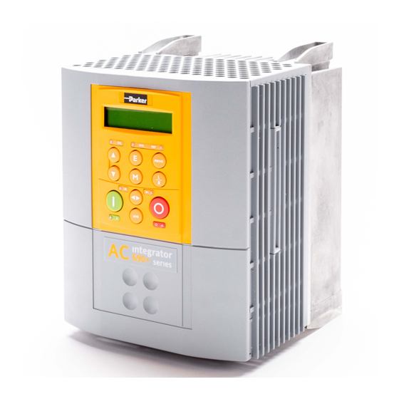
690+ Frame K. The 690+ Series AC Drive is designed for speed control of standard 3-phase induction motors. These larger models are available in a range of ratings for constant torque and quadratic torque applications. -
Page 12: Packaging And Lifting Details
You will find the appropriate diagrams at the rear of each manual. The pages unfold to show a complete block diagram, these will become your programming tool as you become more familiar with the 690+ unit’s software. 690+ Series AC Drive www.comoso.com... -
Page 13: Information For Users Without A Keypad
This symbol identifies important text for users operating the drive using the default (factory) set- DEFAULT up. If the text is italic, such as this, then the information is especially for users without the keypad or suitable PC programming tool. 690+ Series AC Drive www.comoso.com... - Page 14 Getting Started 690+ Series AC Drive www.comoso.com...
- Page 15 690+ Series AC Drive www.comoso.com...
-
Page 16: Drive
RIVE Introduction The 690+ Frame K unit extends the power output of the 690+ series of drives by connecting 690+ Frame G, H or J drives in parallel. These specially adapted drives form a power-sharing, master-slave relationship. A Master plus one or two slaves can be supported, depending upon the required power output. - Page 17 The software is updated to include stack identification and a new PHASE FAIL trip to protect individual drive input bridges in the event of a blown line fuse. Hardware The drives are mechanically identical to the standard 690+ Frame G, H and J drives. 690+ Series AC Drive www.comoso.com...
-
Page 18: Component Identification
(ground) connections usi ng M10 bolts and washers supplied. W ITH Under no circumstances should lifting eyes be used to make the PE / grounding connection. Figure 2-2 690+ Frequency Drive – Frame G - Master illustrated 690+ Series AC Drive www.comoso.com... -
Page 19: Product Range
Ribbon Cable, Tray & Cover LA468328U001 AC Line Choke CO389936U402 Output Choke (Parker SSD Drives can supply) Filter(s) (Parker SSD Drives can supply) Brake Resistors (Parker SSD Drives can supply) * The drive Product Code indicates the requirement for Technology Boxes, Comms Board, Brake Option etc. -
Page 20: Control Features
4 configurable inputs - voltage or current Outputs Analog Outputs 3 configurable outputs - voltage or current Digital Inputs 7 configurable 24V dc inputs, 1 fixed 24V dc input Relay/Digital Outputs 3 relay contacts (volt-free) Table 2-1 Control Features 690+ Series AC Drive www.comoso.com... -
Page 21: Functional Overview
Voltage detection is performed by the control circuits and the switching is performed by the optional dynamic brake circuit. Refer to Chapter 3: Drive Brake Unit for details of the dynamic braking option. 690+ Series AC Drive www.comoso.com... - Page 22 This is a non-isolated RS232 serial link for communication with the keypad. Alternatively, a PC running Parker SSD Drives’ “ConfigEd Lite” Windows-based configuration software (or some other suitable PC programming tool) can be used to graphically program and configure the drive.
- Page 23 An Overview of the Drive 690+ Series AC Drive www.comoso.com...
-
Page 24: Nstalling The
If there is not Additional air sufficient space, redirection of inlet location the exhaust air is required. if required These drives dissipate substantial heat (refer to Chapter 8: “Technical Specificatons” – Electrical Ratings, for Total 690+ Series AC Drive www.comoso.com... -
Page 25: Mounting The Drive
External AC Supply Filter (optional). Refer to page 3-24. • Frame J drives: fit the Main Cooling Fan which is supplied separately. Refer to page 3-5. • For a typical layout refer to Figure 3-2 Wiring Scheme for 690+ Frame K, page 3-7. 690+ Series AC Drive www.comoso.com... -
Page 26: Fitting The External Vent Kit (Frame G)
Fitting the External Vent Kit (Frame G) Note: We recommend that the External Vent Kit is fitted to each drive. Parker SSD Drives Part Numbers: Frame G : LA465720U001 Refer to Drawing HG465731U003 Sheet 2 at the end of this Chapter for top panel and mounting plate hole positions. -
Page 27: Fitting The External Vent Kit (Frames H & J)
9. Fix vent top via (2) M6 x 10 screws (using a 10 mm wrench on the support studs through the grill is helpful in aligning the stud to the hole in the top) and (4) M6 nuts and washers. 690+ Series AC Drive www.comoso.com... -
Page 28: Fitting The Main Cooling Fan (Frame J)
Frame G Frame H Frame J Supply Voltage 110 to 130 VAC, 50/60 Hz Fuse Rating 10 A Supply Voltage 220 to 240VAC, 50/60Hz Fuse Rating Airflow Requirement 750m 1200m 1700m (425CFM) (700CFM) (1000CFM) 690+ Series AC Drive www.comoso.com... -
Page 29: Electrical Installation
2 slots to the right, as viewed from the front of the 2 off 8 off cover drive. Remove the break-outs for the cable tray on the sides of the Terminal Cover as required. Frame Cable/Tray Assembly LA468328U001 LA468328U002 LA468328U003 690+ Series AC Drive www.comoso.com... -
Page 30: Wiring Scheme
AC Line Fuse - semiconductor type Master Power Board DC Fuse - semiconductor type Speed Feedback Technology Box (optional) Product Label Comms Technology Box (optional) Vent Kit and Exhaust Duct (recommended) Cable Tray and Cover (mandatory) Motor Thermistor Terminal 690+ Series AC Drive www.comoso.com... -
Page 31: Connections
The thermistor type supported is PTC `Type A’ as defined in IEC 34- 11 Part 2. The drive uses the following resistance thresholds: Rising temperature trip resistance: 1650 to 4000Ω Falling temperature trip reset resistance: 750 to 1650Ω 690+ Series AC Drive www.comoso.com... - Page 32 The rms value of dc link current in this case can be calculated as: = 1.23 x I (A rms) LINE where I is the rms input current specified in the electrical ratings table in Chapter 8. LINE 690+ Series AC Drive www.comoso.com...
-
Page 33: Control Terminals
11 12 13 14 15 16 17 18 19 20 21 22 23 24 25 26 Speed Setpoint RUNNING HEALTH 220V AC 3A maximum into a resistive load (default) Figure 3-3 Typical Connection to the Control Terminals 690+ Series AC Drive www.comoso.com... -
Page 34: Mandatory Equipment
Rating Guidelines for AC Line Chokes Parker SSD Drives can supply the line chokes listed in Chapter 8: "Technical Specifications" - Line Chokes. If you wish to source your own line choke refer to the individual Electrical Rating tables in Chapter 8 for the relevant rms line currents. - Page 35 3-12 Installing the Drive 480A, 50μH Input Choke Outline Drawing for Frames G & H-220kW - Drawing No. SD12225 (refer to Chapter 8 : “Technical Specifications” - AC Line Choke) 690+ Series AC Drive www.comoso.com...
- Page 36 3-13 Installing the Drive 680A, 35μH Input Choke Outline Drawing for Frames H-280kW & J - Drawing No. SD12226 (refer to Chapter 8 : “Technical Specifications” - AC Line Choke) 690+ Series AC Drive www.comoso.com...
-
Page 37: Output Sharing Choke
3-14 Installing the Drive Output Sharing Choke The 690K requires an output choke to be fitted to each Master and Slave drive. The following chokes are available from Parker SSD Drives: Parker SSD Part Number Frame SIze CO468314U420 CO468314U650 H, J... - Page 38 3-15 Installing the Drive Output Sharing Choke for Frame H & J - CO468314U650 690+ Series AC Drive www.comoso.com...
-
Page 39: Rating Guidelines For Output Sharing Chokes
Rating Guidelines for Output Sharing Chokes Requirements 1. Supplier to advise Parker SSD Drives if they are unable to meet any part of this specification. 2. Supplier is responsible for performing and reporting all testing on these components, (see 4). - Page 40 Insulation Preferred Lead-Out Any alternative lead out must be approved by Parker SSD Drives. The following are to be advised to Parker SSD Drives by the Component Manufacturer : Weight (In Kg) : Dimensions (in mm) : Length (L) :...
-
Page 41: Optional Equipment
2 3 4 5 6 7 8 9 SW1 SW2 2 3 4 5 6 2 3 4 5 6 SW1/SW2 Switch Settings Volts set by SW1 +24V External and SW2 Power Supply positions Figure 3-4 System Board Terminals 690+ Series AC Drive www.comoso.com... -
Page 42: Encoder Connections
To ensure compliance with the EMC Directive the overall cable screen should be connected to the encoder body and to the drive chassis. Recommended cable (pairs individually screened): Belden equivalent 8777 Parker SSD Drives Part Number CM052666 Differential Encoders System Board Terminal B System Board Terminal D... -
Page 43: Technology Options
6055/CNET ControlNet Technology Option Manual HA468029U001 LonWorks 6055/LON LonWorks Technology Option Manual HA468031U001 TB2 Speed Feedback Technology Option Plug-in speed feedback HTTL Encoder option. Technology Box (Frames C, D, E, F, G, H, J) 6054/HTTL 690+ Series AC Drive www.comoso.com... -
Page 44: Fitting The Remote 6901/6911 Keypad
Cutout Dimensions An actual size template is provided with Keypad/6052 Mounting Kit. Figure 3-5 Mounting Dimensions for the Remote-Mounted Keypad 6901/6911 690+ Series AC Drive www.comoso.com... -
Page 45: Dynamic Braking Option
We also recommend that the brake unit heatsink/IGBT assembly is removed from the exhaust duct before installing the unit within the cubicle. 690+ Series AC Drive www.comoso.com... - Page 46 2 off M5 screws on top of cover to 2.5 Nm (1.84 ft-lb). Replace drive front top cover with 2 off ¼ turn fasteners. Fit brake unit cover with M6 captive washer nuts. 690+ Series AC Drive www.comoso.com...
-
Page 47: External Ac Supply Filter
The routing of the connections between the filter, choke and drive module should be chosen to ensure their close proximity. Ensure that the filter output leads are separated from the filter input leads. Failure to achieve this will result in increased conducted emissions. 690+ Series AC Drive www.comoso.com... - Page 48 The conduit shall also be bonded to the motor frame and the cubicle back panel. AC Supply Filter CO467843U340 580.0 Mounting Keyway Detail 105.0 105.0 12.0 24.5 360.0 105.0 20.5 105.0 625.0 24.0 61.5 62.0 110.0 24.0 580.0 22.5 Dimensions are in millimetres 690+ Series AC Drive www.comoso.com...
- Page 49 L1 L2 L3 PE L1 L2 L3 PE Filter LOAD LINE CHOKE CHOKE CHOKE Filter LINE LOAD Filter LOAD LINE Figure 3-8 Typical Wiring Details (schematic) Using 2 off Part No. CO467843U340 per Frame G, H & J 690+ Series AC Drive www.comoso.com...
-
Page 50: Output Contactors
EMC filter’s internal capacitors which are connected between phase and earth. This has been minimised in Parker SSD Drives’ filters, but may still trip out any circuit breaker in the earth system. In addition, high frequency and dc components of earth leakage currents will flow under normal operating conditions. - Page 51 3-28 Installing the Drive 690+ Series AC Drive www.comoso.com...
-
Page 52: Installation Drawings
3-29 Installing the Inverter Installation Drawings The 690+ drive must be securely mounted using all 10 off M8 mounting hole positions as shown. Frame G Typical Cubicle Installation Outline Drawing (HG465731U003 Sheet 1) 690+ Series Frequency Inverter www.comoso.com... - Page 53 3-30 Installing the Inverter Frame G Typical Cubicle Machining (HG465731U003 Sheet 2) 690+ Series Frequency Inverter www.comoso.com...
- Page 54 3-31 Installing the Inverter Frame G Schematic Cubicle Mounting Details (HG468318U003) 690+ Series Frequency Inverter www.comoso.com...
- Page 55 3-32 Installing the Inverter The 690+ drive must be securely mounted using all 10 off M8 mounting hole positions as shown. Frame H Typical Cubicle Installation Outline Drawing (HG465731U002 Sheet 1) 690+ Series Frequency Inverter www.comoso.com...
- Page 56 3-33 Installing the Inverter Frame H Typical Cubicle Machining (HG465731U002 Sheet 2) 690+ Series Frequency Inverter www.comoso.com...
- Page 57 3-34 Installing the Inverter Frame H Schematic Cubicle Mounting Details (HG468318U002) 690+ Series Frequency Inverter www.comoso.com...
- Page 58 3-35 Installing the Inverter The 690+ drive must be securely mounted using all 10 off M8 mounting hole positions as shown. Frame J Typical Cubicle Installation Outline Drawing (HG465731U001 Sheet 1) 690+ Series Frequency Inverter www.comoso.com...
- Page 59 3-36 Installing the Inverter Frame J Typical Cubicle Machining (HG465731U001 Sheet 2) 690+ Series Frequency Inverter www.comoso.com...
- Page 60 3-37 Installing the Inverter HG465731U001 Frame J Schematic Cubicle Mounting Details (HG468318U001) 690+ Series Frequency Inverter www.comoso.com...
- Page 61 3-38 Installing the Inverter 690+ Series Frequency Inverter www.comoso.com...
-
Page 62: Pre-Operation Checks
Re-apply power to the drive and system The drive has Macro 1 installed as the factory default. If you are controlling the drive in Remote control, refer to the Software Product Manual : “Application Macros” for details of other macros. 690+ Series AC Drive www.comoso.com... -
Page 63: Control Philosophy
SPEED CONTROL SPEED SETPOINT SPEED SETPOINT DEFAULT LOCAL START/STOP REMOTE START/STOP LOCAL REMOTE SPEED CONTROL SPEED CONTROL SPEED SETPOINT SPEED SETPOINT REMOTE START/STOP LOCAL START/STOP Figure 4-2 The Four Combinations of Local and Remote Control 690+ Series AC Drive www.comoso.com... -
Page 64: Selecting Local Or Remote Control
Figure 4-3 Control Mode LED Indications mode is in force. Note: The default is for the L/R key to be operative for both Sequencing and Reference Generation, and to be set for Remote control, i.e. both LEDs will be off. 690+ Series AC Drive www.comoso.com... -
Page 65: Initial Start-Up Routines
Reading the Status LEDs The HEALTH and RUN LEDs indicate status. The LEDs are considered to operate in five different ways: SHORT FLASH EQUAL FLASH LONG FLASH HEALTH Figure 4-4 Blank Cover showing LED Operation 690+ Series AC Drive www.comoso.com... -
Page 66: Routine 2: Local Control Using The Keypad
Drive Set-up Using the keypad (or other suitable programming tool) the drive must now be set-up: • as a simple Open-loop Drive (V/F fluxing) • in Sensorless Vector Fluxing mode • in Closed-Loop Vector mode 690+ Series AC Drive www.comoso.com... -
Page 67: Set-Up As An Open-Loop Drive (V/F Fluxing)
(rpm) minus full load slip) MOTOR POLES ** 4 Number of motor poles AUTOTUNE ENABLE FALSE Enables the Autotune feature For more information refer to Chapter 5: “The Keypad” - The QUICK SETUP Menu. 690+ Series AC Drive www.comoso.com... -
Page 68: Set-Up Using The Closed-Loop Vector Mode
Parameter is only set up if drive is configured to run as Closed- loop Vector MAG CURRENT Magnetising current Not measured by Stationary Autotune STATOR RES Per phase stator resistance LEAKAGE INDUC Per phase stator leakage inductance 690+ Series AC Drive www.comoso.com... -
Page 69: Stationary Or Rotating Autotune
AUTOTUNE ENABLE parameter is reset to FALSE. In Closed-loop Vector mode (with an encoder) the encoder sign has been adjusted by the Autotune feature. IMPORTANT: Now perform a SAVE CONFIG to save your new settings. Refer to Chapter 5: “The 690+ Series AC Drive www.comoso.com... -
Page 70: Performing A Stationary Autotune
3 minutes (for the dc link capacitors to discharge) and then swap the motor drive cables M1/U and M2/V. Change the setting of ENCODER INVERT. The encoder sign is now correct for the new motor direction. 690+ Series AC Drive www.comoso.com... -
Page 71: The Start/Stop Mode Explained
Similarly when the JOG input (DIGITAL INPUT 5) is TRUE, the SPEED DEMAND ramps up to the JOG SETPOINT at a ramp rate set by JOG ACCEL TIME (not shown in the diagram). The drive will continue to run at the JOG SETPOINT while the JOG input remains TRUE. 690+ Series AC Drive www.comoso.com... -
Page 72: Starting And Stopping Methods
• To “stop” the remotely controlled drive remove the 24V from the RUN FWD input, terminal With the keypad, or suitable programming tool, the drive can be selected to “Ramp to Stop”, or to “Coast to Stop” at one of two rates (STOP TIME or FAST STOP TIME). 690+ Series AC Drive www.comoso.com... -
Page 73: Ramp To Stop
SPEED DEMAND changes immediately to 0% as soon as the Stop command is given. The power stack is also immediately disabled at this time, causing the load to coast. POWER CIRCUIT DISABLED RUN input REMOTE SETPOINT SPEED DEMAND Speed 0% Figure 4-8 Coast to Stop with a Remote Reference 690+ Series AC Drive www.comoso.com... -
Page 74: Advanced Stopping Methods
When a trip condition is detected, a similar stopping method to NOT COAST STOP is used. The power stack cannot be re-enabled until the trip condition has been cleared and successfully reset. Refer to Chapter 6: “Trips and Fault Finding” for further details. 690+ Series AC Drive www.comoso.com... -
Page 75: Logic Stopping
NOT COAST STOP TRUE REMOTE REVERSE REMOTE REVERSE Digital Input 4 REM TRIP RESET REM TRIP RESET Digital Input 7 TRUE TRIP RST BY RUN FALSE POWER UP START Figure 4-13 Default Sequencing Wiring (Macro 1) 690+ Series AC Drive www.comoso.com... -
Page 76: Starting Several Drives Simultaneously
RUN REV switch causes the drive to run in reverse. Operating the NOT STOP switch (making “NOT STOP” FALSE) at any time causes the drive to stop running. Note: The JOG parameter is never latched in this way. The drive only jogs while the JOG parameter is TRUE. 690+ Series AC Drive www.comoso.com... - Page 77 4-16 Operating the Drive 690+ Series AC Drive www.comoso.com...
-
Page 78: Connecting The Keypad
Note: By default the drive always initialises in Remote control mode, WELCOME SCREEN with the Local control keys inactive, making it unlikely that the motor could be started accidentally. OPERATOR menu at level 1 Remote Mode (default) 690+ Series AC Drive www.comoso.com... -
Page 79: Controlling The Drive Using The Keypad
Local Start/Stop (Seq) mode. STOP/RESET Control - Stops the motor. Only operates when the drive is in Local Sequence mode. Trip Reset - Resets any trips and clears displayed message if trip is no longer active. 690+ Series AC Drive www.comoso.com... -
Page 80: Led Indications
FWD/REV keys. Speed Control (Ref) is controlled from the terminals Start/Stop (Seq) is controlled from the terminals Speed Control (Ref) is controlled using the up ( ) and down ( ) keys Start/Stop (Seq) and Speed Control (Ref) are controlled using the Keypad keys 690+ Series AC Drive www.comoso.com... -
Page 81: The Menu System
VIEW LEVEL, the last parameter in the menu. Note: The contents of the OPERATOR menu remains unchanged for all view levels. Refer to “The Menu System Map”, page 5-6 to see how VIEW LEVEL changes the menu. 690+ Series AC Drive www.comoso.com... -
Page 82: Changing A Parameter Value
E key. Experience will show how to avoid most messages. They are displayed in clear, concise language for easy interpretation. Refer to Chapter 6: “Trips and Fault Finding” for trip messages and reasons. 690+ Series AC Drive www.comoso.com... -
Page 83: The Menu System Map
VALUE FUNC VALUE FUNC 1 VALUE FUNC 20 Note: When VIEW LEVEL is set to OPERATOR, the PROG key also toggles to the VIEW LEVEL parameter in the QUICK SETUP menu. This can be password protected. 690+ Series AC Drive www.comoso.com... - Page 84 PRESET 1 BASIC RAISE/LOWER PRESET 8 SELECTING ADVANCED WILL SKIP FREQUENCIES DISPLAY ALL MENUS S-RAMP ZERO SPEED TRIPS I/O TRIPS STALL TRIP TRIPS HISTORY TRIPS STATUS WINDER COMPENSATION DIAMETER CALC SPEED CALC TAPER CALC TORQUE CALC 690+ Series AC Drive www.comoso.com...
-
Page 85: The Prog Key
• JOG SETPOINT is displayed as SETPOINT (JOG) Pressing the L/R key when in Remote mode takes you directly to the SETPOINT (LOCAL) parameter with the Edit mode enabled. Press the PROG key to return to the previous display. 690+ Series AC Drive www.comoso.com... -
Page 86: The Operator Menu
PARAMETER SELECTION PARAMETER NULL Select/change a function block To select a different instance of this function block, i.e. ANALOG INPUT 2 PARAMETER PARAMETER Select/change a parameter OPERATOR MENU menu at level 4 Figure 4-4 Parameter Selection 690+ Series AC Drive www.comoso.com... -
Page 87: String Entry
NAME Figure 4-5 String Entry Note: For details about user-definable units, scaling factors, limits and coefficients refer to the Software Product Manual, Chapter 1: Programming Your Application - OPERATOR MENU and DISPLAY SCALE function blocks. 690+ Series AC Drive www.comoso.com... -
Page 88: The Diagnostics Menu
The difference between the demanded speed and the actual speed. (Refer to the SPEED LOOP function block) DRIVE FREQUENCY Tag No. 591 Range: —.xx Hz Shows the drive output frequency in Hz. (Refer to the PATTERN GEN function block) 690+ Series AC Drive www.comoso.com... - Page 89 A read-only parameter indicating the state of the brake switch. (Refer to the DYNAMIC BRAKING function block) DRIVE FREQUENCY Tag No. 591 Range: —.x Hz The drive output frequency. (Refer to the PATTERN GEN function block) 690+ Series AC Drive www.comoso.com...
- Page 90 (VALUE) The TRUE or FALSE input, (after any inversion). (Refer to the DIGITAL INPUT function block) DIGITAL INPUT 6 Tag No. 726 Range: FALSE / TRUE (VALUE) The TRUE or FALSE input, (after any inversion). (Refer to the DIGITAL INPUT function block) 690+ Series AC Drive www.comoso.com...
- Page 91 (VALUE) The TRUE or FALSE output demand. (Refer to the DIGITAL OUTPUT function block) DIGITAL OUTPUT 3 Tag No. 737 Range: FALSE / TRUE (VALUE) The TRUE or FALSE output demand. (Refer to the DIGITAL OUTPUT function block) 690+ Series AC Drive www.comoso.com...
-
Page 92: The Quick Setup Menu
DISABLE TRIPS 0000 >> Sub-menu to set disabled trips DISABLE TRIPS + 0040 >> Sub-menu to set disabled trips VIEW LEVEL TRUE Selects full menu for MMI display Table 4-1 Parameters for setting-up the drive 690+ Series AC Drive www.comoso.com... -
Page 93: The System Menu
This menu restores the displayed application/macro to the drive. SYSTEM To restore an application/macro see below. RESTORE CONFIG RESTORE CONFIG RESTORE CONFIG APPLICATION RESTORE CONFIG MACRO 1 RESTORE CONFIG `UP` TO CONFIRM RESTORE CONFIG menu at level 2 690+ Series AC Drive www.comoso.com... - Page 94 MACRO 1. DELETE CONFIG You cannot delete the factory macros. To delete an application see below. DELETE CONFIG PUMP 1 DELETE CONFIG PUMP 2 DELETE CONFIG `UP` TO CONFIRM DELETE CONFIG menu at level 2 690+ Series AC Drive www.comoso.com...
-
Page 95: Selecting The Language
"UP" TO CONFIRM SAVE CONFIG menu at level 2 DISPLAYS OPERATOR MENU PROG (NORMAL ACTION OF PROG KEY) SETPOINT (REMOTE) for example 0.0 % PRESS AGAIN TO RETURN TO PROG PREVIOUS MENU/PARAMETER DIAGNOSTICS menu at level 1 690+ Series AC Drive www.comoso.com... -
Page 96: Quick Tag Information
Note: The drive must be in Configuration mode before links can be edited. Pressing the M key at this point will display the ENABLE CONFIG page. Refer to the Software Product Manual, Chapter 1: “Programming Your Application” - Making and Breaking Links in Configuration Mode. 690+ Series AC Drive www.comoso.com... -
Page 97: Password Protection
You can check that password protection has been removed by repeatedly pressing the E key until the Welcome screen is displayed. Pressing the E key again will NOT display the PASSWORD LOCKED screen. Note: Perform a SAVE CONFIG if you need “no password” to be saved on power-down. 690+ Series AC Drive www.comoso.com... -
Page 98: Power-Up Key Combinations
Select from the expanded SYSTEM menu DELETE CONFIG IMPORTANT: We recommend the menus marked *above are only used by Parker SSD Drives or suitably qualified personnel. Refer to The SYSTEM Menu, page 5-16 for all non-highlighted menus. 690+ Series AC Drive... -
Page 99: Quick Enter Configuration Mode
You can initialise the drive in Configuration Mode by holding the STOP key during power-up. Hold down the key opposite: Power-up the drive, continue HOLD to hold for at least 2 seconds AC MOTOR DRIVE 5.5kW 400V V1.1 for example Menu System 690+ Series AC Drive www.comoso.com... -
Page 100: Trips
DEFAULT Success is indicated by the HEALTH LED (on the unit or MMI) ceasing to flash and returning to a healthy “ON” state. The programming block SEQ & REF::SEQUENCING LOGIC::TRIPPED output is reset to FALSE. 690+ Series AC Drive www.comoso.com... -
Page 101: Using The Keypad To Manage Trips
(refer to COMMS CONTROL menu at level 3) CONTACTOR FBK The CONTACTOR CLOSED input in the SEQUENCING LOGIC function block remained FALSE after a run command was issued SPEED FEEDBACK SPEED ERROR > 50.00% for 10 seconds 690+ Series AC Drive www.comoso.com... - Page 102 OVERSPEED Speed feedback > 150% for 0.1 seconds UNKNOWN An unknown trip - refer to Parker SSD Drives MAX SPEED LOW During Autotune the motor is required to run at the nameplate speed o f the motor. If MAX SPEED RPM limits the speed to less than this value, an error will be reported.
-
Page 103: Automatic Trip Reset
The following function blocks (MMI menus) are used to enable automatic trip resets. Seq & Ref::Auto Restart (Auto-Reset) Seq & Ref::Sequencing Logic Setting Trip Conditions The following function blocks (MMI menus) are used to set trip conditions: Trips::I/O Trips Trips::Trips Status 690+ Series AC Drive www.comoso.com... -
Page 104: Viewing Trip Conditions
If data will not save correctly, the keypad will display a failure message. In this case, the drive has developed a fault and must be returned to Parker SSD Drives. Refer to Chapter 7: “Routine Maintenance and Repair". Fault Finding... -
Page 105: Troubleshooting Leds
LEDs LEDs Slave Power Board Slave Drive Slave 2 (optional) LEDs Slave Power Board Note: Check that all 50-way ribbon cables are correctly fitted between the drives and between the Master and Slave Power Board. 690+ Series AC Drive www.comoso.com... - Page 106 Slave 1 present The Master Power Board has detected that Slave 1 is fitted. Slave 2 present The Master Power Board has detected that Slave 2 is fitted. 690+ Series AC Drive www.comoso.com...
- Page 107 Check wiring to motor and motor itself for earth faults CAL board not fitted Internal fault - consult supplier Internal supply fail Internal fault - consult supplier FPGA not programmed Internal fault - consult supplier 690+ Series AC Drive www.comoso.com...
-
Page 108: Routine Maintenance
• Details of the fault Contact your nearest Parker SSD Drives Service Centre to arrange return of the item. You will be given a Returned Material Authorisation. Use this as a reference on all paperwork you return with the faulty item. Pack and despatch the item in the original packing materials; or at least an anti-static enclosure. -
Page 109: Spares List
Routine Maintenance and Repair Spares List Parker SSD Drives are able to provide guidance regarding the necessary component part to be replaced. The serviceable component parts are listed below. Electro-Mechanical Parts Drive Main Cooling Fan Motor Start Capacitor for Internal Extractor Fan... -
Page 110: Component Replacement
PCBs beneath cover). Re-connect the cable to CON10 and the 4-way op-station cable to PLG9. Re-fit drive top and bottom terminal cover (plastic) via 2 off ¼ turn fasteners at top and bottom of drive. 690+ Series AC Drive www.comoso.com... - Page 111 PCBs beneath cover). 6. Re-connect 4-way op-station cable to PLG9 (see figure 7.1). 7. Re-fit drive top and bottom terminal cover (plastic) via 2 off ¼ turn fasteners at top and bottom of drive. 690+ Series AC Drive www.comoso.com...
- Page 112 PCBs beneath cover). 6. Re-connect 4-way op-station cable to PLG9 (see figure 7.1). 7. Re-fit drive top and bottom terminal cover (plastic) via 2 off ¼ turn fasteners at top and bottom of drive. 690+ Series AC Drive www.comoso.com...
-
Page 113: Fan Replacement
It is possible to replace the drive main cooling fan should the need arise. Having replaced the main cooling fan, ensure that the wiring loom routing/fixing is preserved. This is an electrical safety requirement. Frames G & H Drive Main Cooling Fan and Fan Start Capacitor Replacement 690+ Series AC Drive www.comoso.com... - Page 114 Remove fan mounting nuts. Remove fan and fan start capacitor taking care not to damage other components within drive. Re-connect fan wiring loom and ensure that electrical safety isolation is preserved. Refit the lower panel assembly to the drive. 690+ Series AC Drive www.comoso.com...
- Page 115 VERSION BLOCKS EARTH 2 OFF 120mm SQ GRN/YEL GRN/YEL EARTH 115V AC FAN 230V VERSION CENTRIFUGAL FAN MOTOR RUNNING CAPACITOR Figure 7.5 Wiring Diagram Fan Supply for Frame J, Drg No. HJ 463151 D 002 690+ Series AC Drive www.comoso.com...
-
Page 116: Phase Assembly Replacement
12. 690G : Remove heatsink clamp screws (3 per phase assembly) and remove clamp plates. 690H & J : Loosen heatsink clamps (4 per phase assembly) and rotate through 90°. 13. Carefully remove phase limb assembly. 690+ Series AC Drive www.comoso.com... - Page 117 13. Refit drive front cover (metal) via 4 off ¼ turn fasteners (take care not to damage PCBs beneath cover). 14. Reconnect 4-way op-station cable to PLG9 (see figure 7.1). 15. Refit drive top and bottom terminal cover (plastic) via 2 off ¼ turn fasteners at top and bottom of drive. 690+ Series AC Drive www.comoso.com...
- Page 118 EARTH BONDING WIRE INSULATING CAPS OUTLINE OF CAPACITOR JOINING PHASE LIMB PLATES Output current Sensor SERVICE PLATE CONTROL PCB SUPPORT PANEL INPUT BUSBAR Output current Sensor OUTPUT BUSBAR Figure 7.6 Power Component Identification (Frame G) 690+ Series AC Drive www.comoso.com...
- Page 119 7-12 Routine Maintenance and Repair 690+ Series AC Drive www.comoso.com...
-
Page 120: Echnical Pecifications
380 to 460V (±10%) 50/60Hz XXXX Four digits specifying the mechanical package including livery and mechanical package style: First two digits Livery Standard Parker SSD Drives livery Distributor livery (01-04, 06-99 - Defined customer liveries ) Third digit Mechanical packaging style Standard panel mounting... - Page 121 Note: External braking resistors should be specified and ordered separately. Characters specifying the auxiliary mains power supply. 110 to 120V (±10%), 50/60Hz 220 to 240V (±10%), 50/60Hz Digits specifying engineering special options: No special option 690+ Series AC Drive www.comoso.com...
-
Page 122: Catalog Number (North America)
(External braking resistors should be specified and ordered separately). Characters specifying the systems board: N Not fitted S System board fitted (fitted to Master drive only) Two characters identifying the operating frequency: - - No characters indicates 60Hz operation UK 50Hz operation 690+ Series AC Drive www.comoso.com... - Page 123 B Brake power switch fitted - no braking resistors supplied (External braking resistors should be specified and ordered separately). Characters specifying the systems board: N Not fitted S System board fitted (fitted to Master drive only) 690+ Series AC Drive www.comoso.com...
-
Page 124: Environmental Details
External filters are available for use on earth referenced (TN) supplies only. Prospective Short Frame G Frame H Frame J Circuit Current (PSCC) 100kA maximum 100kA maximum 100kA maximum Earth Leakage Current >>100mA (all models) 690+ Series AC Drive www.comoso.com... -
Page 125: Cabling Requirements For Emc Compliance
Each individual drive connected to the common DC Bus must be protected by DC Link fuses in both the DC+ and DC- lines (semiconductor fuses preferred). The fuse should be capable of breaking an 800V dc supply. Drive 690PG-X/1800 690PH-X/2200 690PH-X/2800 690PJ-X/3150 Fuse Rating (A) 690+ Series AC Drive www.comoso.com... -
Page 126: Electrical Ratings (Master + 1 Slave)
700 Hp 2x 690PH-X/2200 475 kW 2x 690+H-X/0350 800 Hp 2x 690PH-X/2800 600 kW 1088 1120 10.4 11.4 2x 690+H-X/0450 1000 Hp 1162 2x 690PJ-X/3150 650 kW 1175 1235 12.3 13.2 2x 690+J-X/0500 1100 Hp 1272 690+ Series AC Drive www.comoso.com... -
Page 127: Electrical Ratings (Master + 2 Slaves)
1350 1368 12.7 13.9 3x 690+H-X/0350 1200 Hp 1383 3x 690PH-X/2800 900 kW 1631 1681 15.5 16.9 3x 690+H-X/0450 1500 Hp 1743 3x 690PJ-X/3150 1000 kW 1808 1852 18.5 19.8 3x 690+J-X/0500 1600 Hp 1850 690+ Series AC Drive www.comoso.com... -
Page 128: External Ac Supply (Rfi) Filter
Failure to provide the correct line impedance will severely reduce the drives lifetime and could result in catastrophic failure of the drive. The required AC Line Choke line impedance is nominally 3% of the drive rating. Parker SSD Drives can supply the following ac line chokes: Frame Constant/Quadratic... -
Page 129: Internal Dynamic Brake Switch
54/72 162/216 2.08 3x 690+G-X/0300 3x 690PH-X/2200 1680 420/560 1260/1680 84/112 252/336 1.34 3x 690+H-X/0350 3x 690PH-X/2800 1680 420/560 1260/1680 84/112 252/336 1.34 3x 690+H-X/0450 3x 690PJ-X/3150 1890 473/630 1419/1890 95/126 285/378 1.19 3x 690+J-X/0500 690+ Series AC Drive www.comoso.com... -
Page 130: Control Terminals
3A with resistive load. Connection is by a 6-way spring clamp connector. DOUT1_A normally-open relay Default function DOUT1 closed = healthy contacts DOUT1_B DOUT2_A normally-open relay Default function DOUT2 closed = running contacts DOUT2_B DOUT3_A normally-open relay No default function contacts DOUT3_B 690+ Series AC Drive www.comoso.com... -
Page 131: System Board Terminals (Master Drive Option)
1 2 3 4 5 6 Repeat Encoder Output A Output Repeat Encoder Output /A Output Repeat Encoder Output B Output Repeat Encoder Output /B Output Repeat Encoder Output Z Output Repeat Encoder Output /Z Output 690+ Series AC Drive www.comoso.com... -
Page 132: Analog Inputs/Outputs
15-24V dc = ON 0V dc = OFF (-30V dc absolute * range: 19.1V (full load) to 25.1V (no load) minimum, +30V dc threshold absolute maximum) EXT 24Vin - 0.6V Input Impedance 6.8kΩ Sample Rate 690+ Series AC Drive www.comoso.com... - Page 133 8-14 Technical Specifications 690+ Series AC Drive www.comoso.com...
-
Page 134: Requirements For Emc Compliance
For compliance with EMC requirements, we recommend that the “0V/signal ground” is separately earthed. When a number of units are used in a system, these terminals should be connected together at a single, local earthing point. 690+ Series AC Drive www.comoso.com... -
Page 135: Cabling Requirements
Causing RCDs (Residual Current Devices) to trip due to increased high frequency earth current. • Producing increased heating inside the EMC ac supply filter from the increased conducted emissions. These effects can be overcome by adding output filters at the output of the VSD. 690+ Series AC Drive www.comoso.com... -
Page 136: Emc Installation Options
The digital reference is also used for any 24V control. Note: The 690+ uses a single clean earth busbar for analog and digital. 690+ Series AC Drive www.comoso.com... -
Page 137: Sensitive Equipment
EMC output filters • Input or output chokes/transformers • The cable between VSD and motor (even when screened/armoured) • Connections to external braking chopper and resistor (even when screened/armoured) • AC/DC brushed motors (due to commutation) 690+ Series AC Drive www.comoso.com... - Page 138 For correct field wiring connections that are to be made to each terminal refer to Chapter 3: “Installing the Drive” - Power Wiring Connections, and Control Wiring Connections. Terminal Tightening Torque Refer to Chapter 3: "Installing the Drive" - Mechanical Details. 690+ Series AC Drive www.comoso.com...
- Page 139 Power Output Brake Output for Europe for North America 690P/3150/400... 690+/0500/460... 1@3" 1@3" QUADRATIC TORQUE Product Code Model Catalog Code Power Input Power Output Brake Output for Europe for North America 690P/3150/400... 690+/0500/460... 1@3" 1@3" 690+ Series AC Drive www.comoso.com...
- Page 140 The following Terminal Kits are available for the connection of Power Wiring. Drive Catalog Number Constant Quadratic Torque Terminal Kit No. Torque Frame G 690+G-X/0300/460... 300HP 350HP LA465682U004 Frame H 690+H-X/0350/460... 350HP 400HP LA465682U006 690+H-X/0450/460... 450HP 500HP LA465682U008 Frame J 690+J-X/0500/460... 500HP 550HP LA465682U009 690+ Series AC Drive www.comoso.com...
- Page 141 EMC directive and CE mark. Legal Requirements for CE Marking IMPORTANT: Before installation, clearly understand who is responsible for conformance with the EMC directive. Misappropriation of the CE mark is a criminal offence. 690+ Series AC Drive www.comoso.com...
- Page 142 2. Immunity - these standards limit the effect of interference (on this unit) from other electrical and electronic apparatus. Conformance can be demonstrated using the Product Specific Standard. However, as an aid to end users, Eurotherm products are also tested for compliance with the Generic Standard EN61000-6-3 and EN61000-6-4. 690+ Series AC Drive www.comoso.com...
-
Page 143: Certificates
Directive when the low voltage the unit is used directive for We Parker SSD Drives, address as below, We Parker SSD Drives, address as below, declare under our sole responsibility that the declare under our sole responsibility that the as relevant... -
Page 144: Synchronous Motor Control
The use of output contactors is permitted. It is recommended that this type of operation be limited to emergency use only or in a system where the drive can be inhibited before closing or opening this contactor. 690+ Series AC Drive www.comoso.com... -
Page 145: Using Multiple Motors On A Single Drive
Dynamic braking increases the braking capability of the drive by dissipating the excess energy in a high power resistor connected across the dc link, see above. Refer to the Power Wiring Connection Diagrams in Chapter 3. 690+ Series AC Drive www.comoso.com... -
Page 146: High Starting Torque
It is therefore most important for good winder performance that the diameter is reset to the correct value before the machine is started. The following diagrams show typical ways to preset the roll diameter. 690+ Series AC Drive www.comoso.com... - Page 147 The reel speed reference however, needs to be driven from the Line Reference in order to give good acceleration performance for the winder. The following diagram shows the Line Reference and Line Speed signals used to give an improved accuracy winder. 690+ Series AC Drive www.comoso.com...
-
Page 148: Basic Set-Up Instruction
The following information is required from the winding machine manufacturer in order to set up the winder blocks:- • Absolute minimum roll diameter. • Absolute maximum roll diameter. • Absolute maximum line speed. • Motor maximum speed, at smallest roll diameter and maximum line speed. 690+ Series AC Drive www.comoso.com... -
Page 149: Set-Up With No Web Connected To The Winder
Simple Centre Winder Equations It is assumed that the winders operate in constant tension mode. Unwind Line Reference Rewind Tension Tension Belt / Gearbox Belt / Gearbox Speed Speed Torque Torque Motor Motor Figure 10-6 Constant Tension Winder 690+ Series AC Drive www.comoso.com... - Page 150 ⎧ ⎫ Diameter Build ∴ × Power Power Power Power ⎨ ⎬ Motor Inertia Friction Cons Power Range ⎩ ⎭ Here, Constant Power Range motor field weakening range. This parameter field weakening 690+ Series AC Drive www.comoso.com...
- Page 151 The maximum motor speed will exist under the following conditions:- Maximum line speed Smallest core diameter Maximum gearbox ratio Speed Line Speed × 19 1 . Roll Diameter ∴ Speed Speed × Ratio Motor Roll Gearbox 690+ Series AC Drive www.comoso.com...
-
Page 152: 2-Q Common Dc Bus Applications
Because the drives are fed from the AC side, clearing of the DC fuses may not present a run-threatening situation. The drives will remain functional unless the isolated drive regenerates power. Consider using indicating fuses, especially if a drive is permanently regenerating. 690+ Series AC Drive www.comoso.com... - Page 153 SP = Supply Power (kW) V = Supply Line Volts (V) • Fit DC link fusing to protect cabling to each drive. IMPORTANT: Check the voltage rating of any DC link components. Voltages >700V are common. 690+ Series AC Drive www.comoso.com...
-
Page 154: 4-Q Regen Control/Common Dc Bus Applications
Application Notes 4-Q Regen Control/Common DC Bus Applications Introduction A 4-Q REGEN (4 Quadrant Regenerative) control mode is available on all 690+ Series AC Drives that : ♦ use Software Version 5.1 or greater ♦ display “/007” in Block 12 of the (Europe) Product Code, indicating that Special Option 7 is applied (“Y”... -
Page 155: 4-Q Active Front End
LA482470U030 LA482467U055 LA482470U055 LA482468U006 LA482471U006 LA482468U018 LA482471U018 LA482468U037 LA482471U037 LA482468U055 LA482471U055 LA482468U110 LA482471U110 LA482468U220 LA482471U220 LA482468U315 LA482471U315 LA482468U355 LA482471U355 LA482469U006 LA482472U006 LA482469U018 LA482472U018 LA482469U037 LA482472U037 LA482469U055 LA482472U055 LA482469U110 LA482472U110 LA482469U220 LA482472U220 LA482469U315 LA482472U315 LA482469U355 LA482472U355 690+ Series AC Drive www.comoso.com... -
Page 156: Emc Filtering
Typically the regen rating of the system, and hence the rating of the DC contactor and fuses, will be less than motoring requirement as the contactor should not open under load. 690+ Series AC Drive www.comoso.com... -
Page 157: Drive Set-Up
Setting for DC VOLTS DEMAND Parameter Drive Voltage Under Volts Over Volts Recommended Rating (V) Trip Level (V) Trip Level (V) DC VOLTS DEMAND 380V – 460V 410V 820V 720V 220V – 240V 205V 410V 370V 690+ Series AC Drive www.comoso.com... -
Page 158: Macro 8 : 4Q Regen
1 2 3 4 5 6 7 8 9 10 11 12 13 14 15 16 17 18 19 20 21 22 23 24 25 26 CLOSE PRE- CHARGE HEALTH RUNNING 220V AC 3A maximum into a resistive load (default) 690+ Series AC Drive www.comoso.com... -
Page 159: A Single Motor System
(phase, rotation and frequency). This process takes approximately 100ms. After synchronisation, the DC link on the common bus is boosted to approximately 720V (on a 400V product). This high value of DC link volts is required for successful regen operation. 690+ Series AC Drive www.comoso.com... -
Page 160: A Multi-Motor System
Dynamic Braking (eg. for Emergency Stopping purposes) can still be used in this control mode if required. 690+ Series AC Drive www.comoso.com... -
Page 161: A Smart Brake System
When using the Brake Mode, each drive is responsible for pre-charging its own DC Link. When an individual drive is pre-charged and healthy, it connects itself on to the common DC Bus via a DC contactor. The drives disconnect from the common bus if a trip occurs. 690+ Series AC Drive www.comoso.com... -
Page 162: Dc Link Fuses
IXL70F350 CS481084 CS481088 132/200 IXL70F600 CS481085 CS481088 160/250 IXL70F600 CS481085 CS481088 200/300 IXL70F600 CS481085 CS481088 220/350 FWP 800AI CS481086 CS481088 250/400 FWP 800AI CS481086 CS481088 280/450 FWP 800AI CS481086 CS481088 315/500 FWP 900AI CS481087 CS481088 690+ Series AC Drive www.comoso.com... -
Page 163: Pre-Charge Sizing
Refer to the Electrical Ratings tables for Constant Duty motor powers. We recommend that standard Parker SSD Dynamic Braking resistors are used for the external pre-charge circuit. The continuous and peak power capabilities of these resistors are given... -
Page 164: 3-Phase Choke Sizing
The PWM switching produces high levels of harmonic current in the 3% chokes. It is essential to have these properly rated to avoid significant overheating. Suitable chokes have been developed for Parker SSD Drives and their Part Numbers are provided below. 690+ Series AC Drive... - Page 165 3.24 29.65 180/300 LA468345U180 CO468326U220 324.90 6.50 59.46 280/450 LA468345U280 CO468326U315 468.00 9.36 85.64 315/500 LA468345U315 CO468326U355 531.00 10.62 97.17 Note: Lower values for THD of current can be achieved by adding extra line impedance 690+ Series AC Drive www.comoso.com...
-
Page 166: The Default Application
Software Product Manual - Chapter 1: Programming Your Application. The OPERATOR Menu for Macro 0 The default OPERATOR menu is shown below. STARTUP SCREEN SETPOINT (REMOTE) SPEED DEMAND DRIVE FREQUENCY MOTOR CURRENT LOAD DC LINK VOLTS CURRENT LIMITING ENTER PASSWORD 690+ Series AC Drive www.comoso.com... - Page 167 11-2 The Default Application 690+ Series AC Drive www.comoso.com...
-
Page 168: Macro 1: Basic Speed Control (Default)
0..+10 V – [719] TYPE – FALSE – [711] BREAK ENABLE – FALSE – [718] BREAK ENABLE – 0.00 % – [716] BREAK VALUE – 0.00 % – [723] BREAK VALUE – Macro 1: Basic Speed Control (default) 690+ Series AC Drive www.comoso.com... - Page 169 DIGITAL OUTPUT 2 Running 0V = stopped, 24V = running The Operator Menu for Macro 1 The default Operator Menu is shown below. OPERATOR MENU SPEED DEMAND DRIVE FREQUENCY MOTOR CURRENT TORQUE FEEDBACK DC LINK VOLTS 690+ Series AC Drive www.comoso.com...
- Page 170 First issue of HA465746U001. Preliminary Issue. 17512 25/11/03 Vibration details updated. 17756 12/07/07 Company name change. (19591) New certficates and Safety Information (19887) FIRST USED ON MODIFICATION RECORD 690+ Series AC Drive (Frame K) DRAWING NUMBER SHT. 1 ZZ465746 OF 1 www.comoso.com...
- Page 171 www.comoso.com...
Need help?
Do you have a question about the 690+ Series and is the answer not in the manual?
Questions and answers