Magtek DynaWave Installation And Operation Manual
Oem contactless nfc module
Hide thumbs
Also See for DynaWave:
- Demo manual (26 pages) ,
- Instruction manual (61 pages) ,
- Demo manual (27 pages)
Table of Contents
Advertisement
Quick Links
Advertisement
Table of Contents

Subscribe to Our Youtube Channel
Related Manuals for Magtek DynaWave


Summary of Contents for Magtek DynaWave
- Page 1 DynaWave OEM Contactless NFC Module Installation and Operation Manual September 2018 Document Number: D998200265-10 REGISTERED TO ISO 9001:2015 MagTek I 1710 Apollo Court I Seal Beach, CA 90740 I Phone: (562) 546-6400 I Technical Support: (888) 624-8350 www.magtek.com...
- Page 2 Microsoft®, Windows® and .NET® are registered trademarks of Microsoft Corporation. All other trademarks, system names, product names, and trade names are the property of their respective owners. DynaWave| OEM Contactless NFC Module | Installation and Operation Manual Page 2 of 39 (D998200265-10)
- Page 3 Table 0-1 - Revisions Rev Number Date Notes Sep 26, 2018 Initial release DynaWave| OEM Contactless NFC Module | Installation and Operation Manual Page 3 of 39 (D998200265-10)
- Page 4 MagTek’s published specifications. This warranty shall be provided only for a period of one year from the date of the shipment of the product from MagTek (the “Warranty Period”). This warranty shall apply only to the “Buyer” (the original purchaser, unless that entity resells the product as authorized by MagTek, in which event this warranty shall apply only to the first repurchaser).
- Page 5 LIMITATION ON LIABILITY EXCEPT AS PROVIDED IN THE SECTIONS RELATING TO MAGTEK’S LIMITED WARRANTY, MAGTEK’S LIABILITY UNDER THIS AGREEMENT IS LIMITED TO THE CONTRACT PRICE OF THIS PRODUCT. MAGTEK MAKES NO OTHER WARRANTIES WITH RESPECT TO THE PRODUCT, EXPRESSED OR IMPLIED, EXCEPT AS MAY BE STATED IN THIS AGREEMENT, AND MAGTEK DISCLAIMS ANY IMPLIED WARRANTY, INCLUDING WITHOUT LIMITATION ANY IMPLIED WARRANTY OF MERCHANTABILITY OR FITNESS FOR A PARTICULAR PURPOSE.
- Page 6 Consult the dealer or an experienced radio/TV technician for help. Caution: Changes or modifications not expressly approved by MagTek could void the user’s authority to operate this equipment. CUR/UR This product is recognized per Underwriter Laboratories and Canadian Underwriter Laboratories per UL 60950 1, 2nd Edition.
- Page 7 ATTENTION: CUSTOMER SUPPORT. TERMS, CONDITIONS, AND RESTRICTIONS MagTek, Incorporated (the "Licensor") owns and has the right to distribute the described software and documentation, collectively referred to as the "Software." LICENSE: Licensor grants you (the "Licensee") the right to use the Software in conjunction with MagTek products.
- Page 8 Agreement and will not affect the enforceability of any of the remaining provisions. This Agreement shall be governed by the laws of the State of California and shall inure to the benefit of MagTek, Incorporated, its successors or assigns.
-
Page 9: Table Of Contents
Mechanical Maintenance ......................35 Updates to Firmware, Documentation, Security Guidance............35 Removal from Service ........................36 Developing Host Software ........................37 Appendix A Technical Specifications ....................... 38 DynaWave| OEM Contactless NFC Module | Installation and Operation Manual Page 9 of 39 (D998200265-10) -
Page 10: Introduction
NFC allows for faster payments with a quick tap for transaction processing. Whether you need to accept D-PAS®, PayPass™, payWave®, ExpressPay®, Apple Pay®, Android Pay® or any other mobile wallet that supports contactless, DynaWave is ready. Applications Accept contactless payments in almost any environment. -
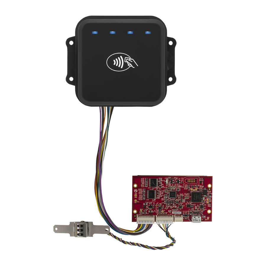
Page 11: About Dynawave Components
1 - Introduction About DynaWave Components Figure 1-1 - DynaWave Major Components DynaWave| OEM Contactless NFC Module | Installation and Operation Manual Page 11 of 39 (D998200265-10) -
Page 12: About Terminology
1 - Introduction About Terminology In this document, DynaWave is referred to as the device. It is designed to be connected to a host, which is a piece of general-purpose electronic equipment which can send commands and data to, and receive data from, the device. -
Page 13: About Solution Planning
Determine what type of host DynaWave will connect to, and what connection type it will use. The host can be a computer or specialty board with a USB port or UART port (for example, MagTek’s mDynamo EMV Contact Reader / Transaction Hub Module). When planning, include any additional support or devices required by the host and its connection, such as physical locations, mounting, and power connections. -
Page 14: Handling
Avoid touching the exposed pins on the connectors when handling the device. For information about ongoing maintenance of the device, such as cleaning, see section 6 Maintenance. DynaWave| OEM Contactless NFC Module | Installation and Operation Manual Page 14 of 39 (D998200265-10) -
Page 15: Electrical Integration
(e.g., functional, legal, security, certification, safety, and so on). When designing the electrical portions of a solution that incorporates DynaWave, consider the following: Review section 1.5 About DynaWave Components for an overall introduction to the device’s physical features and what they are called. -
Page 16: Grounding / Esd Protection
This will help make an informed decision about proper grounding. MagTek strongly recommends solution designs bring in earth ground to the device using ONE AND ONLY ONE of the possible paths: ... -
Page 17: Shielding And Conditioning
MagTek also recommends that all communication cabling should be draped together where possible, and isolated from the earth grounding cable to DynaWave and any other unrelated wiring at the installation site that could potentially couple noise into the device. -
Page 18: Usb Device Port [J3]
2 - Electrical Integration USB Device Port [J3] Do not provide power to DynaWave through both the USB Device Port and UART Port at the same time. Doing so could present a safety hazard and / or permanently damage the device and connected equipment. -
Page 19: Uart Port [J6]
2 - Electrical Integration UART Port [J6] Do not provide power to DynaWave through both the USB Device Port and UART Port at the same time. Doing so could present a safety hazard and / or permanently damage the device and connected equipment. Solution designs should include safeguards against accidental double connections throughout the product’s lifecycle. - Page 20 See Figure 2-3 for an example cable design. See Table 1-1 on page 13 for a list of available cables and accessories MagTek has tested with the device. See section 3.6 for further information about cabling.
- Page 21 2 - Electrical Integration Figure 2-3 - Example UART / Power Cable Figure 2-4 - Example Ground Cable DynaWave| OEM Contactless NFC Module | Installation and Operation Manual Page 21 of 39 (D998200265-10)
-
Page 22: Mechanical Integration
DynaWave. MagTek strongly recommends vetting and testing solution designs before finalizing and deploying them, to make sure the design meets all requirements (e.g., functional, legal, security, certification, safety, and so on). When designing the mechanical portions of a solution that incorporates DynaWave, consider the following: ... -
Page 23: Dimensions
DynaWave are specified in section 3.4 Enclosure Design. On request, MagTek can provide a 3D model of the device’s envelope to assist with the mechanical portion of solution design. MagTek strongly recommends building and testing prototypes with actual devices before finalizing the solution design. -
Page 24: Orientation
The device must be installed such that cardholders have an unobstructed path to tap cards or contactless devices (such as smartphones). The device does not incorporate drain holes, so there are no additional requirements for installation pitch angle to facilitate drainage. DynaWave| OEM Contactless NFC Module | Installation and Operation Manual Page 24 of 39 (D998200265-10) -
Page 25: Enclosure Design
Section 3.2 Dimensions provides detailed dimensions of the device’s installation face. Figure 3-3 - DynaWave Panel Cutout Dimensions in Inches [mm] If the solution will be exposed to the elements, the enclosure must protect the device. The device includes a removable gasket which can be used on its installation face to create a seal with the enclosure. - Page 26 Figure 3-5), those protrusions may also affect NFC performance, and the solution design should include adequate clearance distances between those features and the device. Figure 3-5 - DynaWave Protrusion Clearance Example DynaWave| OEM Contactless NFC Module | Installation and Operation Manual Page 26 of 39 (D998200265-10)
-
Page 27: Mounting
Studs or screws should be size #4 or M3. The washers help spread the load more evenly, and can either be 4 ea. round washers, 2 ea. long flat washers, or one fixing plate. MagTek recommends 2 ea. long washers. See Figure 3-7 for recommended washer / fixing plate dimensions. - Page 28 3 - Mechanical Integration Figure 3-6 - DynaWave Threaded Stud / Nut Mounting DynaWave| OEM Contactless NFC Module | Installation and Operation Manual Page 28 of 39 (D998200265-10)
- Page 29 3 - Mechanical Integration Figure 3-7 - Example Mounting Washer Designs DynaWave| OEM Contactless NFC Module | Installation and Operation Manual Page 29 of 39 (D998200265-10)
-
Page 30: Cabling
2 Electrical Integration. MagTek recommends incorporating cable ties (not included) in the solution design to make sure the cables stay connected during use, and provide strain relief for the device’s connectors. -
Page 31: Installation
4 - Installation Installation This section provides an example of possible instructions to install DynaWave in a specific solution. They are not designed to be distributed as-is to installing technicians. The solution design team must develop solution-specific installation instructions, and may use these steps as a starting point. -
Page 32: Operation
Card and Contactless Device Reading / Transactions Transactions begin when the host software initiates them. Cardholders should tap cards or contactless devices in the contactless landing zone on DynaWave’s front face (see section 1.5 About DynaWave Components). The host software may choose to use the notifications from the device as events to trigger additional guidance (such as audible, visual, or tactile feedback) to the cardholder or operator. -
Page 33: About The Leds
5 - Operation About the LEDs DynaWave provides four LEDs (see Figure 1-1) that provide feedback to operators and cardholders about transaction progress and the internal state of the device. Table 5-1 shows how to interpret the LED patterns. Table 5-1 – General Status LED Meaning... -
Page 34: About Sounds
5 - Operation About Sounds DynaWave’s beeper provides feedback to operators and cardholders about the internal state of the device: The device sounds one short beep on startup to test the beeper and indicate the device is powered on. -
Page 35: Maintenance
The device does not contain any user-serviceable parts. Do not open the enclosure. Periodic cleaning of DynaWave’s exterior may be required. To clean the outside of the device, wipe down the unit with a soft, damp cloth and then wipe with a dry cloth. -
Page 36: Removal From Service
Removal from Service DynaWave does not retain any sensitive data when it is not powered. To remove from service, simply dispose of the device according to standard electronic waste disposal practices in your region. DynaWave| OEM Contactless NFC Module | Installation and Operation Manual... -
Page 37: Developing Host Software
For details, see D998200215 DYNAWAVE PROGRAMMER'S MANUAL (COMMANDS). For more information about developing custom applications that integrate with DynaWave, see the MagTek web site or contact your reseller or MagTek Support Services. DynaWave| OEM Contactless NFC Module | Installation and Operation Manual... -
Page 38: Appendix A Technical Specifications
Apple Pay®, Google Pay, Samsung Pay® User Interface Characteristics Status Indicators: Four Blue LEDs Keypad: Not Applicable Security Characteristics Certifications: Not Applicable Electrical Characteristics Power Inputs: Micro USB-B DynaWave| OEM Contactless NFC Module | Installation and Operation Manual Page 38 of 39 (D998200265-10) - Page 39 ±4kV contact discharge / ±8kV air discharge when properly grounded Vapor Resistance: Not Applicable Reliability Shelf Life: 5 years minimum Magnetic Read Head Life: Not Applicable ICC Read Head Life: Not Applicable DynaWave| OEM Contactless NFC Module | Installation and Operation Manual Page 39 of 39 (D998200265-10)
Need help?
Do you have a question about the DynaWave and is the answer not in the manual?
Questions and answers