Table of Contents
Advertisement
Quick Links
Advertisement
Table of Contents

Related Manuals for Magtek DynaPro 30056072


Summary of Contents for Magtek DynaPro 30056072
- Page 1 Secure Cryptographic Device for PIN and Data Entry Installation and Operation Manual June 2019 Document Number: D99875586-41 REGISTERED TO ISO 9001:2015 MagTek I 1710 Apollo Court I Seal Beach, CA 90740 I Phone: (562) 546-6400 I Technical Support: (888) 624-8350 www.magtek.com...
- Page 2 PUBLICATION RELEASE. NO PART OF THIS DOCUMENT MAY BE REPRODUCED OR TRANSMITTED IN ANY FORM OR BY ANY MEANS, ELECTRONIC OR MECHANICAL, FOR ANY PURPOSE, WITHOUT THE EXPRESS WRITTEN PERMISSION OF MAGTEK, INC. MagTek® is a registered trademark of MagTek, Inc.
- Page 3 Table 0-1 - Revisions Rev Number Date Notes 1.01 Aug 15, 2012 Initial Release 2.01 Sep 10, 2013 Change name from IPAD EMV to DynaPro; include Ethernet and USB descriptions; update dimensions; update images; update formatting. 3.01 Oct 25, 2013 Update page screenshots and EMV transactions throughout section 5 Change “PIN Encryption Device”...
-
Page 4: Limited Warranty
MagTek’s published specifications. This warranty shall be provided only for a period of one year from the date of the shipment of the product from MagTek (the “Warranty Period”). This warranty shall apply only to the “Buyer” (the original purchaser, unless that entity resells the product as authorized by MagTek, in which event this warranty shall apply only to the first repurchaser). -
Page 5: Fcc Information
LIMITATION ON LIABILITY EXCEPT AS PROVIDED IN THE SECTIONS RELATING TO MAGTEK’S LIMITED WARRANTY, MAGTEK’S LIABILITY UNDER THIS AGREEMENT IS LIMITED TO THE CONTRACT PRICE OF THIS PRODUCT. MAGTEK MAKES NO OTHER WARRANTIES WITH RESPECT TO THE PRODUCT, EXPRESSED OR IMPLIED, EXCEPT AS MAY BE STATED IN THIS AGREEMENT, AND MAGTEK DISCLAIMS ANY IMPLIED WARRANTY, INCLUDING WITHOUT LIMITATION ANY IMPLIED WARRANTY OF MERCHANTABILITY OR FITNESS FOR A PARTICULAR PURPOSE. -
Page 6: Ul/Csa
UL/CSA This product is recognized per UL 60950-1, 2nd Edition, 2011-12-19 (Information Technology Equipment - Safety - Part 1: General Requirements), CSA C22.2 No. 60950-1-07, 2nd Edition, 2011-12 (Information Technology Equipment - Safety - Part 1: General Requirements). ROHS STATEMENT When ordered as RoHS compliant, this product meets the Electrical and Electronic Equipment (EEE) Reduction of Hazardous Substances (RoHS) European Directive 2002/95/EC. -
Page 7: Software License Agreement
ATTENTION: CUSTOMER SUPPORT. TERMS, CONDITIONS, AND RESTRICTIONS MagTek, Incorporated (the "Licensor") owns and has the right to distribute the described software and documentation, collectively referred to as the "Software." LICENSE: Licensor grants you (the "Licensee") the right to use the Software in conjunction with MagTek products. - Page 8 Agreement and will not affect the enforceability of any of the remaining provisions. This Agreement shall be governed by the laws of the State of California and shall inure to the benefit of MagTek, Incorporated, its successors or assigns.
-
Page 9: Table Of Contents
0 - Table of Contents Table of Contents Limited Warranty .............................. 4 FCC Information ..............................5 CUR/UR................................5 CE STANDARDS ..............................5 UL/CSA ................................6 RoHS STATEMENT ............................. 6 SOFTWARE LICENSE AGREEMENT ......................... 7 Table of Contents .............................. 9 Introduction ............................. 11 About DynaPro .......................... - Page 10 0 - Table of Contents Operation ..............................28 Operation Overview ........................28 How to Read Device Status ......................29 Card Reading ..........................30 5.3.1 How to Swipe Magnetic Stripe Cards .................. 30 5.3.2 How to Insert Contact Chip Cards ..................30 5.3.3 How to Enter Card Information Manually ................
-
Page 11: Introduction
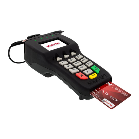
Introduction About DynaPro DynaPro is a secure PIN encryption device combined with MagTek’s 3-Track MagneSafe secure card reader. DynaPro provides the most comprehensive end-to-end security solution to prevent personal cardholder data breaches while bringing convenience and speed to Retail and Financial transactions. - Page 12 1 - Introduction Table 1-1 - Available Models and Options Description Cable NFC SigCap 30056072 DYNAPRO V3, PCI, CONTACTLESS, SIGNATURE CAPTURE, BLACK, USB 6FT 30056073 DYNAPRO V3, TST, CONTACTLESS, SIGNATURE CAPTURE, BLACK, USB 6FT 30056070 DYNAPRO V3, PCI, CONTACTLESS, NO SIGCAP, BLACK, USB 6FT 30056071 DYNAPRO V3, TST, CONTACTLESS, NO SIGCAP, BLACK, USB 6FT...
-
Page 13: Protection For All Points Within The Payment Infrastructure
1 - Introduction Protection for All Points Within the Payment Infrastructure In addition to meeting the requirements established by PCI PTS v3.x, which incorporates SRED features, DynaPro has MagnePrint, a proven embedded security feature that authenticates the debit, credit, or gift card and its encoded track data, rendering counterfeit or cloned cards useless. -
Page 14: Function Buttons (Soft Keys)
DynaPro contains a MagneSafe card reader that encrypts card data at the point of swipe to protect the cardholder’s personal information. The reader incorporates MagTek’s 3-track encrypting IntelliHead, a magnetic read head which has encapsulated and securely potted electronics that reads, decodes, and encrypts card data within the head. -
Page 15: About Major Components
1.14 About Major Components The ferrite bead must remain attached to the stylus cable at all times, do not remove. Changes or modifications not expressly approved by MagTek could void the owner's authority to operate the equipment. The major components of various DynaPro models are shown in the following figures. - Page 16 1 - Introduction Figure 1-5 - Major Components (Back) DynaPro| Secure Cryptographic Device for PIN and Data Entry | Installation and Operation Manual Page 16 of 40 (D99875586-41)
-
Page 17: About Terminology
1 - Introduction 1.15 About Terminology In this document, DynaPro is referred to as the device. It is designed to be connected to a host, which is a piece of general-purpose electronic equipment which can send commands and data to, and receive data from, the device. -
Page 18: Handling And Storage
2 - Handling and Storage Handling and Storage Proper handling of the device throughout delivery, assembly, shipping, installation, usage, and maintenance is very important. Not following the guidelines in this document could damage the device, render it inoperable, and/or violate the conditions of the warranty. Connect the device to a power source as soon as possible after receiving it, and keep it connected to a power source whenever possible to maximize operation. -
Page 19: Installation
It is important to regularly and thoroughly inspect a device in live usage, and its immediate surroundings, to make sure malicious individuals have not tampered with it. MagTek recommends inspection training for all device operators, and an inspection schedule with checkpoints in place to make sure inspections are being done as specified and as scheduled. -
Page 20: How To Connect Dynapro To A Host Via Usb
3 - Installation How to Connect DynaPro to a Host via USB Connecting or disconnecting the USB cable from the back side of DynaPro when the host is ON may clear the encryption keys. To connect DynaPro to a host using the USB connection, connect its USB cable to the USB port on the host as shown in Figure 3-1. -
Page 21: How To Connect Dynapro Go To A Host Via Ethernet
3 - Installation How to Connect DynaPro Go to a Host via Ethernet Figure 3-2 - Ethernet Interface DynaPro| Secure Cryptographic Device for PIN and Data Entry | Installation and Operation Manual Page 21 of 40 (D99875586-41) -
Page 22: How To Install And Remove The Privacy Shield
3 - Installation How to Install and Remove the Privacy Shield To install the privacy shield, follow these steps: 1) Place the clips of the open end of the Privacy Shield into the openings located just above the contact card slot, as shown in Figure 3-3. 2) Pivot the shield down, locking the three clips into the holes located just above the function buttons. -
Page 23: About Mounting
3 - Installation About Mounting The overall dimensions of the device and the mounting hole locations are shown in Figure 3-4. Mounting DynaPro to a surface requires size #4-40 screws. Figure 3-4 - Mounting Dimensions and Cable Access Hole (inches, +/- 0.02 in.) DynaPro| Secure Cryptographic Device for PIN and Data Entry | Installation and Operation Manual Page 23 of 40 (D99875586-41) -
Page 24: About The Rj-25 6-Pin Connector
3 - Installation About the RJ-25 6-pin Connector Figure 3-5 - RJ25 6-Pin Connector RJ25 Signal Connector Pin VBUS USB_DM USB_DP CGND DynaPro| Secure Cryptographic Device for PIN and Data Entry | Installation and Operation Manual Page 24 of 40 (D99875586-41) -
Page 25: Configuration
4 - Configuration Configuration The device has many commands the host software can use to change and monitor its behavior. They are documented in detail in D99875585 DYNAPRO PROGRAMMER'S MANUAL (COMMANDS). In addition, when the device is on the page or showing an error message, operators can view Welcome or change some configuration options using the keypad and display. -
Page 26: How To Configure The Display Brightness
4 - Configuration How to Configure the Display Brightness To adjust the device’s display brightness or contrast, press Left Function Key 5 2 3 Right Function (the numbers 523 correspond to the letters “LCD”) to show the page. Press Adjust LCD decrease the brightness or to increase the brightness. -
Page 27: How To Configure Ethernet Settings
4 - Configuration How to Configure Ethernet Settings The device’s Ethernet port is equipped with Auto-MDX, which allows it to automatically detect and adapt to being connected using either straight-through or crossover Ethernet cables. When the device is connected to the host via Ethernet, on power-up the device attempts to contact a DHCP server to acquire a dynamic IP address. -
Page 28: Operation
5 - Operation Operation Operation Overview Messages shown on DynaPro’s display are customized by the host software developer; therefore, the sequence and content of prompts on the display may vary depending on the requirements of the institution, and may not correspond to the example messages shown here. -
Page 29: How To Read Device Status
An offline code beginning with indicates there is a hardware problem with the device. MagTek recommends the device should be repaired or replaced. An offline code beginning with indicates a problem with either the MSR or PIN key. If it is a new device, it is likely due to the PIN Key not being loaded. -
Page 30: Card Reading
5 - Operation Card Reading 5.3.1 How to Swipe Magnetic Stripe Cards When the appropriate prompt appears (see Figure 5-2 for an example), swipe the card with the magnetic stripe down and facing toward DynaPro’s keypad as shown in Figure 5-2. If the magnetic stripe data can not be read, the host software may prompt the cardholder to swipe the card again. - Page 31 5 - Operation . If the chip card data could not be read, the device may prompt the cardholder to insert the Processing card again. Figure 5-4 - Processing Page Depending on the requirements of the chip card, the device may ask for a signature or PIN. If PIN entry is required, the device asks the cardholder to enter a PIN: Figure 5-5 - Example of Enter PIN Page for EMV Transactions Processing continues, after which DynaPro shows the outcome: Whether the transaction is APPROVED,...
- Page 32 5 - Operation Figure 5-6 - Examples of Pages Approved, Declined or Terminated Transaction data is sent to the host, and as the last step of the EMV transaction process, DynaPro asks the cardholder to remove the chip card by displaying: Figure 5-7 - Examples of Page Remove Card DynaPro| Secure Cryptographic Device for PIN and Data Entry | Installation and Operation Manual Page 32 of 40 (D99875586-41)
-
Page 33: How To Enter Card Information Manually
5 - Operation 5.3.3 How to Enter Card Information Manually If the swiped card’s magnetic stripe is damaged or unreadable, the host software controlling DynaPro may prompt the cardholder to manually enter card information, as shown in the following example: Figure 5-8 - Example Page to Manually Enter Card Data The account number field can be configured with a minimum of 9 and a maximum of 19 digits, or a minimum of 14 and a maximum of 21 digits. -
Page 34: How To Select The Card Type
5 - Operation How to Select the Card Type In a retail setting, the transaction might require the cardholder to select the card type (e.g. “Debit or Credit”). In the following example, the device prompts the cardholder to press the Left function key if the card is a Credit card or to press the Right function key if the card is a Debit card: Figure 5-10 - Example of Page to Select Card Type How to Enter PINs... -
Page 35: How To Use Signature Capture
5 - Operation How to Use Signature Capture If your DynaPro has signature capture capability, the display prompts the cardholder to enter a signature to complete the transaction (see Figure 5-12 for a sample display). After the cardholder has entered his or her signature, the ENTER key must be pressed. -
Page 36: Maintenance
Updates to Firmware, Documentation, Security Guidance In addition to the security guidance in the product manuals, MagTek may provide updates to this document, as well as supplemental security guidance or notices regarding vulnerabilities, at www.magtek.com. -
Page 37: Developing Custom Software
The host must wrap device commands slightly differently depending on the connection type. MagTek produces software development kits (SDKs) with API libraries that provide higher-level functions wrapped around the direct communication protocols like USB and TCP/IP. They also include sample code which the solution development team can compile to demonstrate and test the device, and copy / rewrite to jumpstart solution development. -
Page 38: Appendix A Technical Specifications
Appendix A - Technical Specifications Appendix A Technical Specifications DynaPro Technical Specifications Reference Standards and Certifications ISO 7810 and ISO 7811, AAMVA TDEA (3DES)-CBC using DUKPT PCI PTS v3.x EMV ICC Specifications for Payment Systems Version 4.3 EMV Contactless Level 1 Book D v2.6 MCL v3.1.1 (formerly PayPass) payWave v2.2 Expresspay v3.1... - Page 39 Appendix A - Technical Specifications DynaPro Technical Specifications Signature Capture: On selected models Keypad: 16 Keys (3 Function Keys), raised marking, ADA compliant Electrical Characteristics USB Powered (Power adapter required for contactless or Ethernet) Power Inputs: RJ25 modular jack Power Outputs: Not Applicable Battery Type: Lithium...
- Page 40 Appendix A - Technical Specifications DynaPro Technical Specifications Storage Relative Humidity: Up to 90% non-condensing Vibration Resistance: Not Applicable Shock Resistance: Not Applicable ESD Tolerance (FCC/CE): ±4kV contact discharge / ±8kV air discharge when properly grounded Vapor Resistance: Not Applicable Reliability Magnetic Read Head Life: 1,000,000 card swipes (equivalent to 5 years of operation)
Need help?
Do you have a question about the DynaPro 30056072 and is the answer not in the manual?
Questions and answers