
Related Manuals for Ametek CHANDLER ENGINEERING Twin UCA 4262


Summary of Contents for Ametek CHANDLER ENGINEERING Twin UCA 4262
- Page 1 Model 4262 Twin UCA Operating Manual Revision AA – March 2016 P/N 84-0005 S/N _____________ “ ” : 614007, . . 25 : +7 (342) 262-85-56 : +7 (342) 262-85-60 email: office@techimport.ru www.techimport.ru...
- Page 2 This publication contains the following trademarks and/or registered trademarks: AMETEK, CHANDLER ENGINEERING. These trademarks or registered trademarks and stylized logos are all owned by AMETEK, Inc. All other company, product and service names and logos are trademarks or service marks of their respective owners.
-
Page 3: Table Of Contents
TABLE OF CONTENTS Table of Contents Page General Information..............P-1 Description of Instrument ...................... P-1 Features ..........................P-1 Instrument Specifications ....................... P-1 Section 1 - Installation .............. 1-1 Unpacking the Instrument ...................... 1-1 Utility Requirements ......................1-1 Tools/Equipment Required ....................1-1 Safety Requirements ...................... - Page 4 TABLE OF CONTENTS Ending the Test ......................2-8 Cleaning the Test Cell ......................2-8 Section 3 - Maintenance and Servicing ........3-1 Maintenance ........................3-1 7 Micron Filter Replacement ..................3-1 Regulator Rebuild Instructions ..................3-1 Major Disassembly ....................3-2 Bonnet Disassembly/Reassembly ................
-
Page 5: General Information
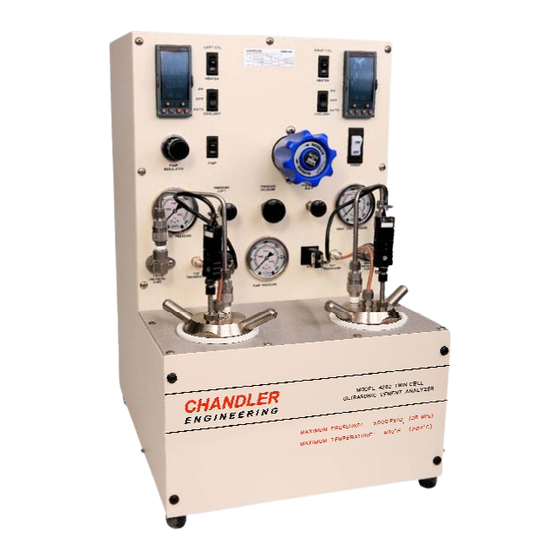
PREFACE General Information Description of Instrument The 4262 Ultrasonic Cement Analyzer is an instrument that is used to test a cement sample at elevated temperature and pressure for the purpose of predicting compressive strength of the cured cement. Features The major features of the 4262 Ultrasonic Cement Analyzer are listed below: •... - Page 6 PREFACE This page is intentionally left blank.
-
Page 7: Section 1 - Installation
SECTION 1 – INSTALLATION Section 1 - Installation Unpacking the Instrument After the consistometer is unpacked, the operating equipment and spare parts on the packing list should be checked to affirm that all have been received and none are damaged. File an insurance claim with your freight carrier if damage has occurred during shipment. -
Page 8: Setting Up The Instrument
SECTION 1 – INSTALLATION • Never exceed instrument maximum pressure and temperature ratings. Disconnect the main power to the instruments during service or repair operations. • Always operate instrument with back panel in place. • Turn off the heater at the completion of a test. Hot water in the open cylinder or drain, when exposed to the atmosphere and heated beyond its boiling point, can cause server burns from steam. -
Page 9: Connecting The Drain Lines
SECTION 1 – INSTALLATION Connecting the Drain Lines Connect the water drain line to the connector labeled WATER OUT and COOLANT OUT on the rear panel of the instrument. The drain system must be capable of handling hot water up to 212°F (100°C) or brief surges of up to 400°F (204°C) steam for short periods of time during initial cooling of the instrument. - Page 10 SECTION 1 – INSTALLATION This page is intentionally left blank.
-
Page 11: Section 2 - Operating Instructions
SECTION 2 – OPERATING INSTRUCTIONS Section 2 – Operating Instructions Front Panel Controls The figure above shows the front panel and all the associated controls. The description of each control is described below. Pump Pressure Adjust Regulator This regulator is used to control the pressure of the air supplied to the pump, which is directly proportional to the hydraulic pressure output of the pump. -
Page 12: Pump Pressure Gauge
SECTION 2 – OPERATING INSTRUCTIONS Pump Pressure Gauge Indicates the pressure of the water supplied from the pump. May be changed, as discussed in the paragraphs above. Each 5 psig (35.5 kPa) pressure applied to the pump results in approximately a 355 psi (2450 kPa) hydraulic pressure output from the pump. Pressure Relief Valve The relief valve or back-pressure regulator may be used to set the upper limit on the system pressure up to 5,000 psig. -
Page 13: Cylinder Pressure Gauge Left/Right
SECTION 2 – OPERATING INSTRUCTIONS Cylinder Pressure Gauge Left/Right Displays pressure inside the test cell. Temperature Controller Left/Right Controls temperature inside the test cell. Heater Switch Left/Right Turns the heater ON or OFF. Switch must be in the ON position during testing and should be in the OFF position as a safety precaution at other times. -
Page 14: Rear Instrument Panel
SECTION 2 – OPERATING INSTRUCTIONS Rear Instrument Panel The rear panel contains all the connections for the cables that connect the instrument to the processor. Main Power Connection Located on the rear instrument panel is an IEC-320 STD C13 connector. Serial RS232/RS485 Connections The rear panel contains all of the connections for the RS-485/RS-232 communications ports used to connect several instruments in one 4262 UCA System. -
Page 15: Preparing The Instrument For A Test
SECTION 2 – OPERATING INSTRUCTIONS Preparing the Instrument for a Test Prior to running a test, the following steps must be performed. Programming the Temperature Controllers Refer to the Chandler Engineering Model 8050 Temperature Controller Manual for complete information on how to program and operate the temperature controller. Setting Up the Test Cell The steps that should be used to set up the test cell are listed below. -
Page 16: Preparing The Test Cell
SECTION 2 – OPERATING INSTRUCTIONS • Screw the bottom plug into the bottom of the cylinder. It is important that the plug be tightened so that it just contacts the top of the cylinder. Further tightening after the plug has contacted the cylinder will not cause more effective sealing and will cause p lug removal difficulty, as well as severe damage to the cylinder and end caps. -
Page 17: Running A Test
SECTION 2 – OPERATING INSTRUCTIONS the vented water and prevent it from running down inside the instrument or into the sensor cavity. The test cell and instrument are now ready to begin a compressive strength test. Running a Test Pressure Control This section describes how the Pump Regulator and Pressure Relief Valves work together for automatic pressure control. -
Page 18: Ending The Test
SECTION 2 – OPERATING INSTRUCTIONS 6. To begin the test, the Temperature Controller program must be started by pressing the EZ1 button on the controller. The output “1” light should begin flashing indicating the control output to the heater and or pump. 7. - Page 19 SECTION 2 – OPERATING INSTRUCTIONS 4. Unscrew and remove the bottom plug of the test cell. 5. Turn the cell over and tap the cement sample out of the test cell with a drift bar and a hammer. 6. Clean the cement and grease from the top and bottom plugs and cylinder with soap and water, or an appropriate solvent.
- Page 20 2-10 SECTION 2 – OPERATING INSTRUCTIONS This page is intentionally left blank.
-
Page 21: Section 3 - Maintenance And Servicing
SECTION 3 – MAINTENANCE AND SERVICING Section 3 - Maintenance and Servicing This chapter describes the basic maintenance that is required for the 4262A, B, and C Instruments. A troubleshooting guide is provided in the next section, in the event that problems occur. -
Page 22: Major Disassembly
SECTION 3 – MAINTENANCE AND SERVICING The regulator is readily disassembled from the front panel. All disassembly can be done WITHOUT removing the regulator from the instrument. Major Disassembly 1. Ensure all pressure is released from the instrument. 2. Rotate the regulator knob (Item 159) fully counterclockwise to remove tension from the regulator assembly. -
Page 23: Major Assembly
SECTION 3 – MAINTENANCE AND SERVICING Caution: Small parts are present within the sensor assembly. Take care not to lose the parts. 3. Remove the sensor components: Valve Stem (Item 101), Spring (Item 104), Spacer (Item 106), Seal (Item 007) and Sensor backup (Item 103). 4. - Page 24 SECTION 3 – MAINTENANCE AND SERVICING This page is intentionally left blank.
-
Page 25: Section 4 - Troubleshooting Guide
SECTION 4 – TROUBLESHOOTING GUIDE Section 4 - Troubleshooting Guide The following table lists symptoms of several common problems, the possible cause of the problem, and the possible solution to the problem. Symptom Possible Cause Possible Solution MAIN POWER circuit- Short circuit in system Disconnect power to instrument breaker switch trips off. - Page 26 SECTION 4 – TROUBLESHOOTING GUIDE Symptom Possible Cause Possible Solution High-pressure tubing or Crack high-pressure thermocouple test cell has air in it. fitting and release any air trapped in the lines or cylinder. High-pressure tubing or Check for water leakage and test cell is leaking.
- Page 27 SECTION 4 – TROUBLESHOOTING GUIDE Symptom Possible Cause Possible Solution Measured parameters Loose wiring. Find and repair loose connections. display zero when they should not. Incorrect or missing I/O Use the SCAN.EXE software to module address in map each I/O channel and make software.
- Page 28 SECTION 4 – TROUBLESHOOTING GUIDE This page is intentionally left blank.
-
Page 29: Section 5 - Replacement Parts
SECTION 5 – REPLACEMENT PARTS Section 5 – Replacement Parts Part Number Description 8051-4262-E or -M Controller, Temperature (English or Metric) 7750-0115 Handle, Top Plug 80-0035 Foam Centering Sleeve 80-0057 Calibration Bar - 3.500 80-0112-03 I/O Board Assembly 84-0012 Top Plug 84-0013 Bottom Plug 84-0015... - Page 30 SECTION 5 – REPLACEMENT PARTS Part Number Description C09298 Filter, 7 Micron, Tee C09366 Pump C09872 Replacement Filter, 7 Micron C09890 Filter, In-line, 60 Micron C10229 Wrench, 5/8” Combination C10961 Seal Kit, Hydraulic Section P-1254 Fitting, 1/4 MPT x 1/4T P-3107 Valve, Solenoid, 220V (Air) P-3387...
-
Page 31: Section 6 - Drawings And Schematics
SECTION 6 – DRAWINGS AND SCHEMATICS Section 6 - Drawings and Schematics Drawing Number Drawing Title 84-0004 Interconnect Wiring 84-0006 Rear Connections 84-0007 Piping Diagram 84-0045 Assembly, Dual UCA Cylinder 84-0046 Front Panel Layout 84-0057 High Temp Cable Assembly 84-0103 Wiring Diagram... - Page 32 ...
- Page 33 CHANDLER ENGINEERING...
- Page 35 REVISIONS ITEM NO. PART NUMBER DESCRIPTION ZONE REV. DESCRIPTION DATE APPROVED P-1954 FITTING, SWAGELOK, B-400-71-4 P-1265 TEE,BRS,UN,1/4TX1/4TX1/4T,SW ECN T7155; UPDATED BOM 3/29/16 P-1255 ELBOW,BRS,1/4MPX1/4T,SW P-3107 VAL,SOL,SS,1/4F,2WY,240VAC P-0866 BUSHG,BRS,RDCG,1/4FPX3/8MP UB C09163 VALVE,SOL,SS,1/4F,2WY,240VAC P-1246 ELBOW,BRS,1/8MNPTX1/4T C05973 ELBOW,SS,1/4FPX1/4MP 84-0113 ASSY, U-TUBE 10 C09352 STEM,SS,QDISC,1/4X1/4OD,SW 11 C09366 PUMP,6150 PSI, 3L-SS-41...
- Page 36 1/4" COPPER COOLANT COOLANT LEFT CYLINDER 10 12 33 -02 10 12 FRONT FRONT PANEL PANEL LEFT CYL RIGHT CYLINDER LEFT PUMP PRESS WATER CYLINDER PUMP 1/8" SS 33 -02 PUMP REGULATOR RIGHT CYLINDER PRESSURE RELIEF PRESSURE RELEASE AIR IN WATER RELIEF VALVE CHANDLER ENGINEERING...
- Page 38 CHANDLER ENGINEERING...
- Page 40 CHANDLER ENGINEERING...
Need help?
Do you have a question about the CHANDLER ENGINEERING Twin UCA 4262 and is the answer not in the manual?
Questions and answers