Table of Contents
Advertisement
Quick Links
OPERATOR'S MANUAL
CHAPTER 1 – SYSTEM DESCRIPTION
The DICKEY-john Control Point™ system uses three-channels (three separate
controlled servo loops) on spreader vehicles to simultaneously control the
spreading of granular and liquid ice-control materials. Two channels control
granular and liquid application rates and the third channel precisely controls
spinner speed to maintain even material coverage over the desired spread
width. The dispensing rate varies directly with ground speed to ensure accu-
rate product application.
Material can also be spread at a preset "BLAST" application rate. This is
normally a very large rate to instantly adjust the target APR (application rate)
for covering bridges and intersections with a much heavier amount of material.
GRANULAR CHANNEL CONFIGURATION
The granular channel controls the amount of material dumped onto the
spinner plate(s). To do this, the Control Point™ monitors a tachometer style
feedback sensor located on the V-box drag chain or tailgate auger. A resultant
drive signal adjusts the conveyor mechanism speed to deliver the target
application rate (APR) by regulating the hydraulic valve position.
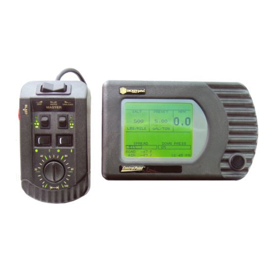
Figure 1. System Components
CONTROL POINT™
SYSTEM DESCRIPTION/ 1
11001-1100-199904 Revision A
Advertisement
Table of Contents

Subscribe to Our Youtube Channel
Related Manuals for Dickey-John Control Point


Summary of Contents for Dickey-John Control Point
- Page 1 GRANULAR CHANNEL CONFIGURATION The granular channel controls the amount of material dumped onto the spinner plate(s). To do this, the Control Point™ monitors a tachometer style feedback sensor located on the V-box drag chain or tailgate auger. A resultant drive signal adjusts the conveyor mechanism speed to deliver the target application rate (APR) by regulating the hydraulic valve position.
- Page 2 LIQUID CHANNEL CONFIGURATION The liquid channel controls the application rate of prewetting or deicing materials. When prewetting, the Control Point™ Console monitors a flowmeter style feedback sensor. When deicing, either a flowmeter or pressure style feedback can be used. Using feedback data, the pumping mechanism output adjusts the target application rate by either regulating pump speed or flow blocking.
- Page 3 9. Audible and visual alarms for system and operator errors. SYSTEM COMPONENT DESCRIPTIONS A DICKEY-john Control Point™ system consists of six basic components; (1) Console, (2) Switch Module, (3) ground speed sensor, (4) feedback devices to monitor material application, (5) actuator devices to regulate material application, and (6) harnesses to interconnect all system devices.
- Page 4 The Switch Module harness plugs into the Console and contains connectors for both keyboard and PC interface as described above. The operator controls the real-time functions of the Control Point ™ system from the seven switches on the Switch Module. (See Figure 3).
- Page 5 HOW TO OBTAIN TECHNICAL SUPPORT For prompt and courteous assistance and answers to your questions, call DICKEY-john Technical Support at (217) 438-3371 or Fax (217) 438-6012 or 438-6539. For toll-free calls in either the USA or Canada, dial 1-800-637-3302. CONTROL POINT™...
- Page 6 OPERATOR'S MANUAL 6/ SYSTEM DESCRIPTION CONTROL POINT™ 11001-1100-199904 Revision A...
- Page 7 Perform the following procedures only after the system is installed, properly programmed and calibrated. Practice the following procedures with the vehicle stationary to gain familiarity with the operating controls and screens before applying product. Figure 3. Switch Module Controls and Definitions CONTROL POINT™ OPERATING PROCEDURES/ 7 11001-1100-199904 Revision A...
- Page 8 A screen briefly shows the DICKEY-john logo followed by the OPERATE screen (See Figure 6). If the console does not power on, the console button was used to properly power down the unit.
- Page 9 If the switch is held, the value repeats until reaching a preset limit. If changed while the vehicle is moving, the new target APR displays for approximately two seconds, then reverts to the actual APRs. CONTROL POINT™ OPERATING PROCEDURES/ 9 11001-1100-199904 Revision A...
- Page 10 Each section is hollow until activated. 7. Observe the area for alarm messages. Alarm messages appear (flashing) in the middle of the screen, above the SPREAD WIDTH bar (See Figure 7). 10/ OPERATING PROCEDURES CONTROL POINT™ 11001-1100-199904 Revision A...
- Page 11 3. Press the INC/DEC +/-” switch of the appropriate channel (granular or liquid), in either direction, to move the point- er up or down on the left side of either list. CONTROL POINT™ OPERATING PROCEDURES/ 11 11001-1100-199904 Revision A...
- Page 12 The CURRENT TOTALS screen (See Figure 9) appears showing totals accumulated for the current product selected. To see other totals, return to the MATERIAL/MANUAL SELECT screen and select those products. 12/ OPERATING PROCEDURES CONTROL POINT™ 11001-1100-199904 Revision A...
- Page 13 Screen traveled during application, and hours elapsed this season for each product in both the AUTO and BLAST modes. The totals can only be cleared in the Program Mode (key- board). CONTROL POINT™ OPERATING PROCEDURES/ 13 11001-1100-199904 Revision A...
- Page 14 1. Back up to the appropriate location and momentarily press UNLOAD. The actuators open fully for those channels turned on from the switch module. 2. To stop the unload operation, move the MASTER switch to the OFF position. 14/ OPERATING PROCEDURES CONTROL POINT™ 11001-1100-199904 Revision A...
- Page 15 CALIBRATION DATA RECORD sheets at the rear of this manual. In the event of Console damage or lost data, rapid recovery is assured. If the Control Point™ Console ever requires replacement, all values can be transferred directly to the new Console via the keyboard.
- Page 16 To use the keyboard, proceed as follows; Figure 14. Basic Screens Layout 1. If the Control Point™ is on, turn the power off and then connect the keyboard to the console harness connector (See Figure 1).
- Page 17 All programming steps should be performed in the order given to ensure proper entries for all parameters. The MASTER Switch must be OFF before functions can be selected with the keyboard. CONTROL POINT™ KEYBOARD PROGRAMMING/ 17 11001-1100-199904 Revision A...
- Page 18 Choices are in miles, miles-feet, square feet, or square yards. If Metric, choices are in kilometers, kilometers- meter, and square meter. This list only allows one selection. Pressing the ENTER key is not necessary to accept the choice. 18/KEYBOARD PROGRAMMING CONTROL POINT™ 11001-1100-199904 Revision A...
- Page 19 Y (YES) to display French (or other), NO to display English. The system displays English and one other language, usually French Canadian. Contact DICKEY-john for available alternative languages. b. Select KEYBOARD from the screen. N (NO) selects an English keyboard, Y (YES) selects French.
- Page 20 AUTO and BLAST modes. The season totals can only be cleared from the Accu- mulator Function (F9). 20/KEYBOARD PROGRAMMING CONTROL POINT™ 11001-1100-199904 Revision A...
- Page 21 DRV FREQ (Drive Frequency) – Represents the valve manufacturer’s suggested drive frequency, as shown on the valve specification sheet. The rated drive frequency for the DICKEY-john servo valve is 100 Hz. CONTROL POINT™ KEYBOARD PROGRAMMING/ 21 11001-1100-199904 Revision A...
- Page 22 Note: The system drives only one type of granular mechanism. Variables (SERV DRV, DRV FREQ, etc.) for all four materials remain the same except for the SPR CON. 22/KEYBOARD PROGRAMMING CONTROL POINT™ 11001-1100-199904 Revision A...
- Page 23 RATE 1. Other rates are selected by pressing the “+/– ” switch on the Switch Module. c. APP START (Step method) – Defines the APR starting point. d. IC/DC STP (Step method) - Sets the increase/decrease step value. CONTROL POINT™ KEYBOARD PROGRAMMING/ 23 11001-1100-199904 Revision A...
- Page 24 OPERATE screen wherever that material appears. 4. Press F2 to return to the GRANULAR APPL RATE screen (See Figure 23). If other granular materials require programming, repeat the above procedures for those materials. 24/KEYBOARD PROGRAMMING CONTROL POINT™ 11001-1100-199904 Revision A...
- Page 25 DRV FREQ (Drive Frequency) - Represents the valve manufac- turer’s suggested drive frequency, as shown on the valve specifica- tion sheet. The rated drive frequency for the DICKEY-john servo valve is 100 Hz. f. PWM OFFSET - Represents the valve operating range starting point (position flowmeter begins generating pulses).
- Page 26 5. If the anti-icing booms require configuration, select the 5 key from the LIQUID CONFIGURATION screen. The screen appearing shows five boom sections for selecting (See Figure 27). 26/KEYBOARD PROGRAMMING CONTROL POINT™ 11001-1100-199904 Revision A...
- Page 27 Liquid 2 (Anti-ice) to avoid having to use the Material Select Screen to make the change. To use the Pre-wet/Anti-icing auto switch input feature, SEC- TION 5/AUTO ANTI-ICING configuration must be set as follows: Section Enabled NO Boom Input CONTROL POINT™ KEYBOARD PROGRAMMING/ 27 11001-1100-199904 Revision A...
- Page 28 APP START (Step method) – Defines the start-point APR. d. IC/DC STP (Step method) - Sets the increase/decrease step value. e. MIN APP (Step method) – Defines the minimum APR limit for the product. 28/KEYBOARD PROGRAMMING CONTROL POINT™ 11001-1100-199904 Revision A...
- Page 29 USING THE CALIBRATION MENU (F6) Calibration is discussed in the next Chapter. All calibration constants not entered in this Chapter during PROGRAMMING must be determined by performing the related calibrations in the next chapter. CONTROL POINT™ KEYBOARD PROGRAMMING/ 29 11001-1100-199904 Revision A...
- Page 30 GROUND SPEED CALIBRATION. Those vehicles equipped with a two-speed axle require two constants, CONSTANT 1 and CONSTANT 2. Depending upon axle-shifter polarity, CON- STANT 1 may be either the Lo-speed axle or the Hi-speed axle. 30/KEYBOARD PROGRAMMING CONTROL POINT™ 11001-1100-199904 Revision A...
- Page 31 DRV FREQ (Drive Frequency) - Represents the valve manufac- turer’s suggested drive frequency, as shown on the valve specifi- cation sheet. The rated drive frequency for the DICKEY-john servo valve is 100 Hz. e. PULSE FDBK (Pulse Feedback) - YES indicates a pulsed feedback sensor for closed loop control.
- Page 32 The question asks if a change from the existing status (enable or disable) is desired. YES causes the ENABLE/DISABLE CLEAR selection to alternate. A setting of NO leaves the ENABLE/DIS- ABLE CLEAR status unchanged. 32/KEYBOARD PROGRAMMING CONTROL POINT™ 11001-1100-199904 Revision A...
- Page 33 TRUCK ID - This screen allows entering an identifying name for the truck which can be changed at anytime. The entry is changed by typing the new name and then pressing the ENTER key to accept the change. CONTROL POINT™ KEYBOARD PROGRAMMING/ 33 11001-1100-199904 Revision A...
- Page 34 OPERATOR'S MANUAL PERFORMING SYSTEM RESPONSE (F11) After all configuration constants have been entered for a given vehicle, the SYSTEM RESPONSE must be performed in preparation for spreading materials (See Chapter 4). 34/KEYBOARD PROGRAMMING CONTROL POINT™ 11001-1100-199904 Revision A...
- Page 35 System calibration defines the spreader configuration characteristics for optimum accuracy of the Control Point system. Performing the following procedures in the order outlined ensures the greatest accuracy when finished.
- Page 36 (See Figure 35). The console automatically detects when the axle ratio has been changed. To calibrate, simply change the axle ratio and rerun. Press the ESC key or any F key to leave the Calibration screen. 36/SYSTEM CALIBRATION CONTROL POINT™ 11001-1100-199904 Revision A...
- Page 37 OPERATOR'S MANUAL CALIBRATION SYSTEM RESPONSE (F11) These constants adjust the response time of the Control Point™ system to the Figure 36. System Response hydraulic and mechanical systems. This procedure determines the System Calibration Screens Response (SYS RSPNS) and related constants (VALV BOOST, PWM OFFSET, PWM SAT, and AFILT) for each of the three control channels (granular, liquid, and spinner).
- Page 38 Decreasing the AFILT may reduce the problem but also causes the system to become more sluggish. Typically, this value does not require changing but check the response time if fine tuning becomes necessary. 38/SYSTEM CALIBRATION CONTROL POINT™ 11001-1100-199904 Revision A...
- Page 39 Repeat as necessary. The maximum value for SAT is 100. 3. If the spinner turns too fast, decrease the SAT value until a satisfactory maximum speed is obtained. The SAT value must be greater than the OFFSET value. CONTROL POINT™ SYSTEM CALIBRATION/ 39 11001-1100-199904 Revision A...
- Page 40 Press the granular channel “+/-” switch on the Switch Module, as required, to obtain a normal discharge rate. The number in the middle of the screen shows the counts accumulating from the APR sensor. 40/SYSTEM CALIBRATION CONTROL POINT™ 11001-1100-199904 Revision A...
- Page 41 See Appendix A, Item 1 for steps required to calculate the new spreader constant, which is then keyboard entered on the (F3) GRANULAR CON- FIGURATION screen. Alternatively, the GRANULAR CALIBRATION routine can be repeated to correct this type of APR error. CONTROL POINT™ SYSTEM CALIBRATION/ 41 11001-1100-199904 Revision A...
- Page 42 5. In the case only where the liquid channel is propelled by the hydraulic system, start the engine, keeping the vehicle stationary. Engage the hydraulic system, and increase engine RPMs to normal operating range. 42/SYSTEM CALIBRATION CONTROL POINT™ 11001-1100-199904 Revision A...
- Page 43 See Appendix A, Item 2 to calculate the modified flowmeter constant, which is then keyboard entered on the LIQUID CONFIGURATION (F5) screen. Alternatively, the LIQUID CALI- BRATION routine can be repeated to correct this type of APR error. CONTROL POINT™ SYSTEM CALIBRATION/ 43 11001-1100-199904 Revision A...
- Page 44 Even without known changes, the SYSTEM RE- SPONSE CALIBRATIONS should be performed at minimum intervals of one year. A good rule of thumb is to recalibrate all three control channels at the start of each spreader season. 44/SYSTEM CALIBRATION CONTROL POINT™ 11001-1100-199904 Revision A...
- Page 45 OPERATOR'S MANUAL CHAPTER 5 – SYSTEM INSTALLATION These instructions describe the installation of the Control Point™ Console, Switch Module, and system harness assemblies. The Console mounts on the vehicle dashboard or other surface suitable for operator viewing using an U- bracket.
- Page 46 Switch Module at the desired location. If placed on the vehicle seat, it must be secured in a suitable manner (possibly using Velcro™ strips) to ensure the control settings are not accidently changed or activated. Figure 41. Console Mounting 46/SYSTEM INSTALLATION CONTROL POINT™ 11001-1100-199904 Revision A...
- Page 47 These are defined as the sensor, actuator, ground speed, boom sense, and hopper level cables. Notes: CAUTION: Make the Control Point™ battery connections last to ensure no accidental shorts occur during harness handling. • Use dust caps provided on all...
- Page 48 RS-232 connectors. CAUTION: Verify battery voltage is 12 volts, NOT 24 volts. Finally, connect both Control Point™ Main Harness battery leads directly to the vehicle battery. Attach the RED wire to the positive battery terminal and the BLACK wire to the negative terminal.
- Page 49 Sense 5 line can be connected as a pre-wet/anti-ice selector input. CAUTION: Verify battery voltage is 12 volts, NOT 24 volts. Finally, connect both Control Point™ Main Harness battery leads directly to the vehicle battery. Attach the RED wire to the positive battery terminal and the BLACK wire to the negative terminal.
- Page 50 OPERATOR'S MANUAL Figure 43. System Harness Layout 50/SYSTEM INSTALLATION CONTROL POINT™ 11001-1100-199904 Revision A...
- Page 51 OPERATOR'S MANUAL CHAPTER 6 – SYSTEM TROUBLESHOOTING The Control Point™ system contains six basic components, each with a specific function. Component failures normally react in predictable ways, making fault isolation relatively easy. If certain components are not operat- ing properly, such as a hydraulic pump or motor, system performance is degraded and the console may incorrectly appear to be at fault.
- Page 52 GRN and BLK wires. Absence of either voltage indicates a broken or shorted wire within the cable assembly or a cor- roded pin in the connector. If voltages are present, replace the conveyor sensor. 52/SYSTEM TROUBLESHOOTING CONTROL POINT™ 11001-1100-199904 Revision A...
- Page 53 4. If the failure continues, replace the MASTER switch module and then the console. Note: The Control Point™ system can continue operating without a “true” ground speed sensor input by setting the MANUAL SPEED to YES in the GROUND SPEED CONFIGURATION (F7) screen. With this enabled, the console simulates an artificial ground speed signal which appears on the display.
- Page 54 5. Check for drag due to snow and ice buildup. ○ ○ ○ ○ ○ ○ ○ ○ ○ ○ ○ ○ ○ ○ ○ ○ ○ ○ ○ ○ ○ ○ ○ ○ ○ ○ ○ ○ ○ ○ ○ 54/SYSTEM TROUBLESHOOTING CONTROL POINT™ 11001-1100-199904 Revision A...
- Page 55 Response on the Liquid Channel, (F11). ○ ○ ○ ○ ○ ○ ○ ○ ○ ○ ○ ○ ○ ○ ○ ○ ○ ○ ○ ○ ○ ○ ○ ○ ○ ○ ○ ○ ○ ○ ○ CONTROL POINT™ SYSTEM TROUBLESHOOTING/ 55...
- Page 56 (+12V). 2. If voltages are present and actuator does not rotate, replace the actuator. If voltages are not present replace main harness, valve extension cable, or console. Corrective action for a Sprayer system 56/SYSTEM TROUBLESHOOTING CONTROL POINT™ 11001-1100-199904 Revision A...
- Page 57 ○ ○ ○ ○ ○ ○ ○ ○ ○ ○ ○ ○ ○ ○ ○ ○ ○ ○ ○ ○ ○ ○ ○ ○ ○ ○ ○ ○ ○ ○ CONTROL POINT™ SYSTEM TROUBLESHOOTING/ 57 11001-1100-199904 Revision A...
- Page 58 OPERATOR'S MANUAL Figure 44. System Wiring Diagram, Console and Cab Harness 58/SYSTEM TROUBLESHOOTING CONTROL POINT™ 11001-1100-199904 Revision A...
- Page 59 OPERATOR'S MANUAL Figure 45. System Wiring Diagram, Truck Harness and Sensors CONTROL POINT™ SYSTEM TROUBLESHOOTING/ 59 11001-1100-199904 Revision A...
- Page 60 OPERATOR'S MANUAL 60/SYSTEM TROUBLESHOOTING CONTROL POINT™ 11001-1100-199904 Revision A...
- Page 61 Similarly, the nozzle constant can be adjusted for a pressure based system as follows: EXAMPLE: If NZLE CONT is 0.8 and Target APR is 50 GAL/MILE but Actual APR is known to be 45 GAL/MILE, adjust nozzle constant using the above formula: CONTROL POINT™ SYSTEM DESCRIPTION/ 61 11001-1100-199904 Revision A...
- Page 62 1. V-Box spreaders have a different SPR CON for each gate setting. 2. The number of pulses per revolution for several Dj shaft sensors are: 360 for P/N 46436-017X (standard Control Point™ shaft sensor). 60 for P/N 10844-000X. 900 for P/N 10837-00XX.
- Page 63 APPENDIX B – MECHANICAL ADJUSTMENTS ADJUSTING VALVE MANUALLY If the system contains a DICKEY-john dual servo valve which does not open in either AUTO or UNLOAD, manual adjustment of the valve position is possible to allow continued spreading. The procedure is as follows: 1.
- Page 64 OPERATOR'S MANUAL ELIMINATING CONVEYOR OR SPINNER CREEP If the system contains a DICKEY-john dual servo valve which “creeps” (moves slowly when it should be stationary), correct as follows: 1. Park the vehicle and place the system in MANUAL SPEED operation.
- Page 65 __________ PWM OFFSET ___________ ___________ __________ __________ PWM SAT ___________ ___________ __________ __________ SYS RSPNS ___________ ___________ __________ __________ VALV BOOST ___________ ___________ __________ __________ AFILT ___________ ___________ __________ __________ CONTROL POINT™ CALIBRATION DATA RECORD SHEET/ 65 11001-1100-199904 Revision A...
- Page 66 __________ RATE 8 ___________ ___________ __________ __________ RATE 9 ___________ ___________ __________ __________ RATE 10 ___________ ___________ __________ __________ BLST RATE ___________ ___________ __________ __________ CHN LBL ___________ ___________ __________ __________ 66/CALIBRATION DATA RECORD SHEET CONTROL POINT™ 11001-1100-199904 Revision A...
- Page 67 __________ PWM OFFSET ___________ ___________ __________ __________ PWM SAT ___________ ___________ __________ __________ SYS RSPNS ___________ ___________ __________ __________ VALV BOOST ___________ ___________ __________ __________ AFILT ___________ ___________ __________ __________ CONTROL POINT™ CALIBRATION DATA RECORD SHEET/ 67 11001-1100-199904 Revision A...
- Page 68 __________ RATE 8 ___________ ___________ __________ __________ RATE 9 ___________ ___________ __________ __________ RATE 10 ___________ ___________ __________ __________ BLST RATE ___________ ___________ __________ __________ CHN LBL ___________ ___________ __________ __________ 68/CALIBRATION DATA RECORD SHEET CONTROL POINT™ 11001-1100-199904 Revision A...
- Page 69 DICKEY-john within 30 days after such defect is discovered, DlCKEY-john will (at our option) either replace or repair said part.
Need help?
Do you have a question about the Control Point and is the answer not in the manual?
Questions and answers