Table of Contents
Advertisement
Quick Links
OPERATOR'S MANUAL
Safety Notices ..................................................................................................... 1
Introduction ......................................................................................................... 3
System Overview .............................................................................................................. 3
Installation and Setup ......................................................................................... 5
Console Mounting ............................................................................................................. 5
Console Harness Installation ............................................................................................ 6
Power Connection ............................................................................................................. 7
Implement Harness/Module Connection ........................................................................... 9
Module Order ................................................................................................................................... 9
Module Installation ........................................................................................................................... 9
Module Setup Examples ................................................................................................................ 12
Connecting Sensors to Modules .................................................................................................... 14
Hopper Level Sensors .................................................................................................................... 15
Harnesses ....................................................................................................................... 18
12 Row Harness ............................................................................................................................. 18
16 Row Harness ............................................................................................................................. 18
Shaft Speed Module Harness ........................................................................................................ 19
RS485 Extension Harness ............................................................................................................. 19
Startup ............................................................................................................... 21
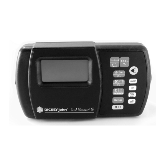
Switchpad Overview ....................................................................................................... 21
On/Off ............................................................................................................................................. 21
Alarm .............................................................................................................................................. 21
Setup .............................................................................................................................................. 21
Min Avg Max Scan ......................................................................................................................... 21
Select Row ...................................................................................................................................... 21
Select .............................................................................................................................................. 22
Set................................................................................................................................................... 22
Start Stop Reset ............................................................................................................................. 22
Back ................................................................................................................................................ 22
Operate 1 ....................................................................................................................................... 22
Operate 2 ....................................................................................................................................... 23
Operate 3 ....................................................................................................................................... 23
Setup Mode ..................................................................................................................... 24
Setup Constants ............................................................................................................................. 24
Seed Flow Alarm Adjustment ......................................................................................................... 26
Population Hi Limit ......................................................................................................................... 27
Population Lo Limit ......................................................................................................................... 27
Row Width ...................................................................................................................................... 27
Implement Width ............................................................................................................................ 28
Ground Speed Source ................................................................................................................... 28
Distance Calibration ....................................................................................................................... 28
Automatic Configuration ................................................................................................................. 29
Split Row Configuration .................................................................................................................. 30
Number of Seed Modules .............................................................................................................. 31
Row Status ..................................................................................................................................... 32
Total Number Of Rows Configured ................................................................................................ 33
Number of Fan Speed Sensors ...................................................................................................... 33
Number of Shaft Speed Sensors ................................................................................................... 35
Seed Manager SE ®
11001-1359A-200810
/I
Advertisement
Table of Contents

Related Manuals for Dickey-John Seed Manager


Summary of Contents for Dickey-John Seed Manager
-
Page 1: Table Of Contents
Split Row Configuration ........................30 Number of Seed Modules ......................31 Row Status ............................. 32 Total Number Of Rows Configured ....................33 Number of Fan Speed Sensors ...................... 33 Number of Shaft Speed Sensors ....................35 Seed Manager SE ® 11001-1359A-200810... - Page 2 Pressure Lo Limit Warning ......................58 Hopper Lo Warning ........................59 Battery Voltage Warning ......................... 60 Self Test Error Codes ..................61 Connector Pinouts ......................65 Setup Record Sheet ....................... 66 Setup Record Sheet ....................... 67 Warranty ......................69 II / Seed Manager SE 11001-1359A-200810...
-
Page 3: Safety Notices
Use of the word CAUTION without the safety alert symbol indicates a potentially hazardous situation which, if not avoided, may result in equipment damage. SAFETY NOTICES / 1 Seed Manager SE® 11001-1359A-200810... - Page 4 OPERATOR’S MANUAL 2 / SAFETY NOTICES Seed Manager SE 11001-1359A-200810...
-
Page 5: Introduction
(2) fan (RPM) inputs, three (3) shaft speed (RPM) inputs, two (2) pressure inputs, seven (7) hopper level inputs, and (1) ground speed input. It is compatible with DICKEY-john standard and Hi-Rate seed sensors. Implement configuration data is stored in nonvolatile memory retaining information even when disconnected from the tractor battery. - Page 6 OPERATOR’S MANUAL 4 / INTRODUCTION Seed Manager SE 11001-1359A-200810...
-
Page 7: Installation And Setup
5. Insert the two rubber washers between the bracket and console. 6. Tilt console so that the J1 connector on the rear of the console is accessible. 7. Temporarily tighten the two knob screws. INSTALLATION AND SETUP / 5 Seed Manager SE 11001-1359A-200810... -
Page 8: Console Harness Installation
OPERATOR’S MANUAL CONSOLE HARNESS INSTALLATION The J1 connector on the back of the console connects all input and output ® signals to the Seed Manager SE console. The primary tractor harness is shown in (Figure Harness contains connectors for •... -
Page 9: Power Connection
Due to the power requirements for 3. Install or connect an existing ground speed sensor. The ground speed ® the Seed Manager SE system, sensor may be one of three types – radar, reluctance, or Hall Effect. A the battery connections must be radar sensor or reluctance sensor connects directly to the designated made directly to the tractor battery. - Page 10 Negative or Positive Source Connections IMPORTANT: Before welding on the frame or chassis, be certain to disconnect battery leads. Failure to do so could result ® in damage to the Seed Manager 8 / INSTALLATION AND SETUP Seed Manager SE 11001-1359A-200810...
-
Page 11: Implement Harness/Module Connection
OPERATOR’S MANUAL IMPLEMENT HARNESS/MODULE CONNECTION ® The Seed Manager SE System uses any combination of three basic module types each with specific harness configurations. Module Types: • 12 Row Material Flow • 16 Row Material Flow • Shaft Speed The following requirements must be observed when connecting modules to the bus: •... - Page 12 Attach to frame using 1/4 x 20 bolts or other fastening devices as illustrated in (Figure Do not use the enclosure as a guide when drilling. Do not overtighten nuts as this may damage the mounting tabs on the enclosure. 10 / INSTALLATION AND SETUP Seed Manager SE 11001-1359A-200810...
- Page 13 • Securely tighten tie strap. • Install a second tie strap toward the label end of the enclosure for additional support. Figure 9 Material Flow Module Installation (Tie Strap) IMPLEMENT FRAME INSTALLATION AND SETUP / 11 Seed Manager SE® 11001-1359A-200810...
-
Page 14: Module Setup Examples
Four Module Setup (two modules are connected to P1 and two to P2) Three Module Setup (All modules connected to P1) Three Module Setup (one module connected to P1 and 2 connected to P2) 12 / INSTALLATION AND SETUP Seed Manager SE 11001-1359A-200810... - Page 15 As the previous examples show, b1 is always identified as the LAST module connected to P1. The remaining modules on P1 are numbered sequentially, along with any modules connected to P2. INSTALLATION AND SETUP / 13 Seed Manager SE 11001-1359A-200810...
-
Page 16: Connecting Sensors To Modules
When correctly connected, row 1 sensor should be connected to the Row 1 input on b1. The monitor will then number the sensors from 1 to n starting on b1, then b2, and so on. Figure 11 Correct Install Correct Install 14 / INSTALLATION AND SETUP Seed Manager SE 11001-1359A-200810... -
Page 17: Hopper Level Sensors
2. The following shows an example configuration with hopper sensors connected and how they would be identified by the console. Figure 13 Hopper Sensor Connection to 12 Row Material Flow Module INSTALLATION AND SETUP / 15 Seed Manager SE 11001-1359A-200810... - Page 18 Module is connected between Material Flow Modules, any hopper sensors connected are numbered in the order in which they are detected as shown below. Figure 14 Hopper Sensor Connection to Shaft Speed Module 16 / INSTALLATION AND SETUP Seed Manager SE 11001-1359A-200810...
- Page 19 Shaft Speed Module on the bus. (Figure 15) shows a complete example of a system setup and how each connected sensor would be identified. INSTALLATION AND SETUP / 17 Seed Manager SE 11001-1359A-200810...
-
Page 20: Harnesses
OPERATOR’S MANUAL HARNESSES 12 ROW HARNESS 16 ROW HARNESS 18 / INSTALLATION AND SETUP Seed Manager SE 11001-1359A-200810... -
Page 21: Shaft Speed Module Harness
OPERATOR’S MANUAL SHAFT SPEED MODULE HARNESS RS485 EXTENSION HARNESS INSTALLATION AND SETUP / 19 Seed Manager SE® 11001-1359A-200810... - Page 22 OPERATOR’S MANUAL 20 / INSTALLATION AND SETUP Seed Manager SE 11001-1359A-200810...
-
Page 23: Startup
Successive depressions then cause 1 2 3 . . . stepping from one row to the next. In the Setup Mode, this switch allows stepping through the rows while entering Row Status. STARTUP / 21 Seed Manager SE 11001-1359A-200810... -
Page 24: Select
Setup Mode to return to the previous Setup Mode screen. OPERATE 1 l l l l This switch is used to select Population, Spacing, or Ground Speed Mode. Successive presses of the switch will change to the next mode. 22 / STARTUP Seed Manager SE 11001-1359A-200810... -
Page 25: Operate 2
Successive presses of the switch will change to the next mode. OPERATE 3 Selects Area, Seed Count, or Distance Accumulator Mode. Successive 1 2 3 ... presses of the switch will change to the next mode. STARTUP / 23 Seed Manager SE® 11001-1359A-200810... -
Page 26: Setup Mode
NOTE: To allow rapid recovery from an entry error, it is important to record all values of constants on the SETUP RECORD sheet on the last page of this manual immediately after console entry. 24 / STARTUP Seed Manager SE 11001-1359A-200810... - Page 27 000.0 999.9 Blockage Mode Configuration Population Filter Population Scalar Sensor/Module Self-Test English/Metric Units English To exit the Setup Mode, press any of the three Operate switches. Exiting automatically stores the last constant changed. STARTUP / 25 Seed Manager SE 11001-1359A-200810...
-
Page 28: Seed Flow Alarm Adjustment
1 seed every 4 seconds 1 seed every 5 seconds 1 seed every 6 seconds 1 seed every 7 seconds 1 seed every 8 seconds 1 seed every 9 seconds 1 seed every 10 seconds 26 / STARTUP Seed Manager SE 11001-1359A-200810... -
Page 29: Population Hi Limit
Population Lo Limit Display 4. ROW WIDTH This is the distance in inches (centimeters) between rows with a resolution of 0.1. (Figure 20) shows a row width of 38.0 inches. Figure 20 Row Width Display STARTUP / 27 Seed Manager SE 11001-1359A-200810... -
Page 30: Implement Width
Pressing the Set switch causes the lower right display to toggle between “d1”, “r1”, or “d2”. If a digital (radar or Hall Effect) type ground speed sensor ® is used and is connected directly to the Seed Manager Console, press the SET switch until “d1” appears. -
Page 31: Automatic Configuration
4. Verify the detected configuration by reviewing the setup constants for the number of seed modules, seed sensors, hopper sensors, and pressure sensors before beginning implement operation. (Figure shows the Automatic Configuration screen. STARTUP / 29 Seed Manager SE 11001-1359A-200810... -
Page 32: Split Row Configuration
Tw in Rrow s (OXXOOXXOOXXOO) Tw in Row s (XXOOXXOOXXOO) Tw in Row s (XOOXXOOXXOOXX) Every 4th row OFF (OOOXOOOXOOOX) Every 4th row OFF (OOXOOOXOOOXOOO) Every 4th row OFF (OXOOOXOOOXOOO) Every 4th row OFF (XOOOXOOOXOOO) 30 / STARTUP Seed Manager SE 11001-1359A-200810... -
Page 33: Number Of Seed Modules
Sensor/Module Self-Test and error codes will be generated if this value does not match the actual number of seed sensors. (Figure shows twelve (12) seed sensors configured on module 3. STARTUP / 31 Seed Manager SE 11001-1359A-200810... -
Page 34: Row Status
SELECT ROW switch to advance to the next row. When the status of all rows is correctly entered, press SETUP to advance to the next Setup constant. Figure 29 Row Status Display 32 / STARTUP Seed Manager SE 11001-1359A-200810... -
Page 35: Total Number Of Rows Configured
(Figure 31) shows a configuration of two (2) fan speed sensors. Figure 31 Fan Speed Sensor Display STARTUP / 33 Seed Manager SE 11001-1359A-200810... - Page 36 SELECT switch to advance one step to the right of the right most digit, then press the SET switch to toggle between ON and OFF. (Figure 33) shows a limit of 500 RPM with the warning enabled. Figure 33 Hi Limit Fan Speed Display 34 / STARTUP Seed Manager SE 11001-1359A-200810...
-
Page 37: Number Of Shaft Speed Sensors
Hi and Lo Limit warnings. (Figure 35) shows a configuration of three (3) shaft speed sensors. Figure 35 Shaft Speed Sensor Display STARTUP / 35 Seed Manager SE 11001-1359A-200810... - Page 38 SELECT switch to advance one step to the right of the right most digit, then press the SET switch to toggle between ON and OFF. (Figure 37) shows a limit of 65 RPM with the warning enabled. Figure 37 Hi Limit Shaft Speed Display 36 / STARTUP Seed Manager SE 11001-1359A-200810...
-
Page 39: Setup Mode Continued
(Figure 39) shows a configuration of five (5) hopper sensors. Figure 39 Hopper Level Display STARTUP / 37 Seed Manager SE 11001-1359A-200810... -
Page 40: Number Of Pressure Sensors
Pressing the SET switch will toggle the status of the warning between ON and OFF. (Figure 41) shows a Pressure Sensor Hi Limit of 18.0 with the warning enabled. Figure 41 Hi Limit Pressure Display 38 / STARTUP Seed Manager SE 11001-1359A-200810... -
Page 41: Blockage Mode Configuration
Description All Rows are configured for displaying Population First Row of each Module is configured for displaying Population- All other rows are configured for Blockage Only All Rows are configured for Blockage Only STARTUP / 39 Seed Manager SE 11001-1359A-200810... -
Page 42: Population Filter
Blockage Mode Display 18. POPULATION FILTER ® In certain applications the Seed Manager SE, due to its rapid update rate, might exhibit fluctuations in population and spacing that are undesirable. The population filtering option applies an averaging filter to the population and spacing calculations. -
Page 43: Population Scaling Factor
Alarm switch. (Figure 47) shows the Sensor/Module Self Test screen. Figure 47 NOTE: For a full description of all the error codes and their meanings, Sensor Self Test Display see the ERROR CODES section. STARTUP / 41 Seed Manager SE 11001-1359A-200810... -
Page 44: English/Metric Units
Figure 49 Boot Number Display Boot Version Number DICKEY-john’s Service Department may request the customer to observe and record the four (4) different 4-digit numbers (to identify the “boot memory” software version) in the unlikely event field problems occur. The first 4-digit number shows on the upper numeric display at the same time a “b1”... - Page 45 OPERATOR’S MANUAL Flash Version Number DICKEY-john’s Service Department may require the four (4) different 4-digit numbers (to identify the “flash memory” software version) if a field problem occurs. The first 4-digit number shows on the upper numeric display at the same time an “F1”...
- Page 46 OPERATOR’S MANUAL 44 / STARTUP Seed Manager SE 11001-1359A-200810...
-
Page 47: Operation
To zero the accumulated Run Hours, press the START STOP RESET switch for one (1) second while Run Hours are displayed. (Figure 52) shows Run Hours of 47.5. Figure 52 Run Hours Display OPERATION / 45 Seed Manager SE 11001-1359A-200810... -
Page 48: Population
MIN AVG MAX SCAN switch until the SCAN message displays while in Population function. (Figure 53) shows a population of 158,400 seeds/acre on row nine (9) while in Population Scan. Figure 53 Population Scan Display 46 / OPERATION Seed Manager SE 11001-1359A-200810... -
Page 49: Population Min Avg Max
BACK switch will cause the display to return to the previous valid population row. (Figure 55) shows a population of 157,400 seeds/acre on row twelve (12) while in Population Select Row. Figure 55 Population Select Row Display OPERATION / 47 Seed Manager SE 11001-1359A-200810... -
Page 50: Seed Spacing
OPERATE 1 switch until the SPEED message appears on the display. The ground speed sensor can be either radar, Hall Effect, or reluctance type. (Figure 57) shows a ground speed of 5.6 MPH. Figure 57 Ground Speed Display 48 / OPERATION Seed Manager SE 11001-1359A-200810... -
Page 51: Fan Speed
OPERATE 2 switch until “S1”, “S2”, or “S3” displays in the lower numerical display. (Figure 59) shows a shaft speed of 53.0 RPM. Figure 59 Shaft Seed Display OPERATION / 49 Seed Manager SE 11001-1359A-200810... -
Page 52: Pressure
When a total area of 99999 acres (hectares) is exceeded, it will roll over to zero (0). (Figure 61) shows Area Accumulator 1 with 1674.3 acres. Area Accumulator 3 is not resettable. Figure 61 Area Accumulator 1 Display 50 / OPERATION Seed Manager SE 11001-1359A-200810... -
Page 53: Seed Count
(meters) is exceeded the accumulator rolls over to zero (0). Any other Operate Mode function can be selected while Distance Accumulator is running without affecting the actual distance accumulation. (Figure 63) shows a running distance accumulator with 783.6 feet measured. OPERATION / 51 Seed Manager SE 11001-1359A-200810... -
Page 54: Speed Area Mode
To accumulate area in the Speed Area Mode, the lift switch must indicate the implement is down. Run Hours accumulate only when the implement is down. The Distance Accumulator function is independent of the lift switch status. 52 / OPERATION Seed Manager SE 11001-1359A-200810... -
Page 55: Alarms
OPERATOR’S MANUAL ALARMS ® Priority levels are assigned to the Seed Manager SE alarms as shown in (Figure 64) with level one (1) being the highest. If two alarm conditions are detected at the same time only the higher priority alarm displays. If alarms are the same level, both display simultaneously. -
Page 56: All Rows Failed
However, it is very important to remember to immediately repeat the SETUP MODE Distance Calibration before resuming operation if a different ground speed sensor has been installed. Otherwise, the previously determined Distance Calibration Constant will be 54 / ALARMS Seed Manager SE 11001-1359A-200810... -
Page 57: Population Hi Limit Warning
(Figure 66) shows a Population Hi Limit Warning on row four (4) with a row population of 34,600 seeds per acre. Figure 66 Population Hi Limit Warning Display POPULATION LIMIT ALARMS / 55 Seed Manager SE 11001-1359A-200810... -
Page 58: Population Lo Limit Warning
(Figure 68) shows a Fan Speed Hi Limit Warning on fan speed sensor one (1) with a fan speed of 2,387 RPM. Figure 68 Fan Speed Hi Limit Warning Display 56 / ALARMS Seed Manager SE 11001-1359A-200810... -
Page 59: Fan Speed Lo Limit Warning
(Figure 70) shows a Shaft Speed Hi Limit Warning on shaft speed sensor one (1) with a shaft speed of 1,592 RPM. Figure 70 Shaft Speed Hi Limit Warning Display ALARMS / 57 Seed Manager SE 11001-1359A-200810... -
Page 60: Shaft Speed Lo Limit Warning
Pressure Lo Limit in the SETUP MODE. The alarm beeps for three (3) seconds and the pressure sensor number and actual pressure, in oz/in (kPa), display. If multiple pressure sensors fall below the limit, the pressure sensor numbers display sequentially, along with their respective pressures. 58 / ALARMS Seed Manager SE 11001-1359A-200810... -
Page 61: Hopper Lo Warning
HOPPER and LO messages. If multiple hopper sensors signal a low material level, the hopper sensor numbers display sequentially. (Figure 74) shows a Hopper Lo Warning on hopper two (2). Figure 74 Hopper Lo Warning Display HOPPER ALARMS / 59 Seed Manager SE 11001-1359A-200810... -
Page 62: Battery Voltage Warning
The warning beeps reoccur each time the monitor is powered on. (Figure 75) shows the battery symbol in the Operate Mode Speed function with a ground speed of 3.7 MPH. Figure 75 Battery Voltage Warning Display 60 / ALARMS Seed Manager SE 11001-1359A-200810... -
Page 63: Self Test Error Codes
OPERATOR’S MANUAL SELF TEST ERROR CODES ® The Seed Manager SE Console performs a Self Test upon power up and when selected in SETUP MODE. At the end of the Self Test, the console will either show PASSED and cycle through all of the seed rows or the console displays the appropriate error codes that were detected. - Page 64 OPERATOR’S MANUAL 62 / SELF TEST ERROR CODES Seed Manager SE 11001-1359A-200810...
- Page 65 Monitor dead. 1. Blown console fuse. 1. Check console fuse. If it blows again, contact 2. Poor battery connections. DICKEY-john Technical Support to replace console at 3. Cut or broken battery cable. 1-800-637-3302. 4. Low battery voltage. 2. Clean and tighten battery connections.
- Page 66 CODE E30 X Too few seed sensors are 1. Failed seed sensors. 1. Contact DICKEY-john Technical Support at connected to module X (X is 2. Number of Seed Sensors for Module X 1-800-637-3302 for a replacement sensor. the number of the module, Configuration is incorrect.
-
Page 67: Connector Pinouts
OPERATOR’S MANUAL CONNECTOR PINOUTS Console Seed Manager SE Non RS-232 Version Seed Manager SE RS-232 Version FUNCTION PIN # FUNCTION PIN # FUNCTION PIN # PROGRAM OUT 1 PROGRAM OUT 1 PROGRAM OUT 2 PROGRAM OUT 2 RS-485A RS-485 A... -
Page 68: Setup Record Sheet
Number of Pressure Sensors Pressure Sensor 1 Hi Limit Pressure Sensor 1 Lo Limit Pressure Sensor 2 Hi Limit Pressure Sensor 2 Lo Limit Blockage Mode Configuration Population Filter Population Scaling 66 / SELF TEST ERROR CODES Seed Manager SE 11001-1359A-200810... -
Page 69: Setup Record Sheet
Number of Pressure Sensors Pressure Sensor 1 Hi Limit Pressure Sensor 1 Lo Limit Pressure Sensor 2 Hi Limit Pressure Sensor 2 Lo Limit Blockage Mode Configuration Population Filter Population Scaling SELF TEST ERROR CODES / 67 Seed Manager SE 11001-1359A-200810... - Page 70 OPERATOR’S MANUAL 68 / SELF TEST ERROR CODES Seed Manager SE 11001-1359A-200810...
-
Page 71: Warranty
Europe: DICKEY-john Europe S.A.S, 165, boulevard de Valmy, 92706 – Colombes – France TEL: 33 (0) 1 41 19 21 80, FAX: 33 (0) 1 47 86 00 07 WEB: www.dickey-john.eu Copyright 2008 DICKEY-john Corporation Specifications subject to change without notice.
Need help?
Do you have a question about the Seed Manager and is the answer not in the manual?
Questions and answers