Table of Contents
Advertisement
Quick Links
Advertisement
Table of Contents

Related Manuals for Dickey-John Control Point


Summary of Contents for Dickey-John Control Point
- Page 1 ® S I N C E 1 9 6 6 CONTROL POINT ® CONTROL SYSTEM...
-
Page 2: Table Of Contents
Pre-programming ......................25 Using the Keyboard and Screens ................... 26 Miscellaneous Menu (F12) ....................29 Blast Setup ............................. 29 Time/Date Setup ..........................30 System Units ..........................30 Serial Port Configuration ........................ 31 Service Menu ..........................32 Control Point® 11001-1489-201702 Rev B... - Page 3 Proportional Valve Spinner Calibration ................... 78 Granular Materials Calibration (F6) ................79 Granular Calibration Fine Tuning ................... 81 Liquid Materials Calibration (F6) ..................81 Liquid Calibration Fine Tuning ......................84 Calibrating Spinner Width (F6) ..................84 Troubleshooting ....................87 Control Point® 11001-1489-201702 Rev B...
- Page 4 OPERATOR’S MANUAL Appendix A Converting Constants ..............97 Fine Tuning Application ....................97 Calculating Spreader Constants ..................98 Calibration Data Record Sheet ................99 Warranty ......................107 Control Point® 11001-1489-201702 Rev B...
- Page 5 OPERATOR’S MANUAL Control Point® 11001-1489-201702 Rev B...
-
Page 6: Safety Notices
DISCLAIMER DICKEY-john reserves the right to make engineering refinements or procedural changes that may not be reflected in this manual. Material included in this manual is for informational purposes and is subject to change without notice. - Page 7 OPERATOR’S MANUAL ® 2 / SAFETY NOTICES Control Point 11001-1489-201702 Rev B...
-
Page 8: Introduction
GRANULAR CHANNEL CONFIGURATION The granular channel controls the amount of material dumped onto the ® spinner plate(s). The Control Point monitors a tachometer-style feedback sensor located on the V-box drag chain or tailgate auger. A resultant drive signal adjusts the conveyor mechanism speed to deliver the target application rate (APR) by regulating the hydraulic valve position. -
Page 9: Liquid Channel Configuration
In open loop systems, the hydraulic valve position is relative ® to the width adjust knob setting on the Control Point Switch Module. The user must determine the spread-width accuracy needed. Technical assistance is available through DICKEY-john Technical Support at PH#1-800-637-2952. -
Page 10: Console
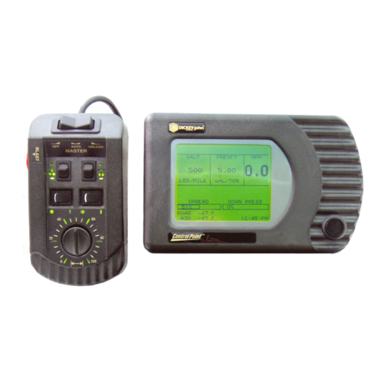
OPERATOR’S MANUAL SYSTEM COMPONENTS ® A DICKEY-john Control Point system consists of six basic components: 1. Console 2. Switch module 3. Ground speed sensor 4. Feedback devices to monitor material application 5. Valve control devices to regulate material application 6. Harnesses to interconnect all system devices Figure 2 shows components in a block diagram. -
Page 11: Switch Module
The Standard Switch Module harness plugs into the Console and contains connectors for both keyboard and PC interface as described above. The ® operator controls the real-time functions of the Control Point system from the seven switches on the Switch Module (refer to Figure 3). -
Page 12: Valve Control Devices
(including two-speed axle, hopper level sensor, and boom sense inputs). Retro Harness Assembly-Connects a Control Point console to an ICS2000 harness (refer to Figure 53 in Troubleshooting section). Other extension harnesses-Other extension harnesses are available that allow for flexible sensor arrangement. - Page 13 OPERATOR’S MANUAL ® 8 / INTRODUCTION Control Point 11001-1489-201702 Rev B...
-
Page 14: System Installation
(4) Five 1/4 inch split washers (5) Two rubber washers (46390-0900) (6) Two knob screws (20072-0022) (7) Three 1/4 - 20 x 3/4 hex bolts (8) Retaining clip (46649-0350) (9) Two #6 self-locking hex nuts ® Control Point SYSTEM INSTALLATION / 9 11001-1489-201702 Rev B... -
Page 15: Console Placement
If placed on the vehicle seat, it must be secured in a suitable manner (possibly using Velcro™ strips) to ensure the control settings are not accidently changed or activated. ® 10 / SYSTEM INSTALLATION Control Point 11001-1489-201702 Rev B... -
Page 16: Switch Module To Console Connection
These are defined as the sensor, actuator, ground speed, boom sense, and hopper level cables. 2. Use dust caps provided on all unused connectors, both internal and external. This includes keyboard and RS-232 connectors. ® SYSTEM INSTALLATION / 11 Control Point 11001-1489-201702 Rev B... -
Page 17: Main Harness Connection
Verify battery voltage is 12 volts, NOT 24 volts. ® 7. Connect both Control Point main harness battery leads directly to the vehicle battery. Attach the RED wire to the positive battery terminal and the BLACK wire to the negative terminal. -
Page 18: Checking Operation
OPERATOR’S MANUAL CHECKING OPERATION 1. After completing the installation, turn on the ignition switch. The Console screen should power on displaying the DICKEY-john name, logo screen, software version, and then the OPERATE screen (refer to Figure 9). 2. Refer to the Startup and Familiarization section for additional testing. - Page 19 Sensor Granular (& Spinner) 12V Relay Liquid Valve Gate Height Sensor Flowmeter Ð Tank Level Road Watch Battery Adapter Down Pressure Granular Application Rate Hopper Level Sensor Sensor Spinner Sensor ® 14 / SYSTEM INSTALLATION Control Point 11001-1489-201702 Rev B...
-
Page 20: Start-Up And Familiarization
START-UP PROCEDURE 1. Verify the Switch Module Master Switch is in the OFF position as shown in Figure 6. If the Master Switch is in the AUTO position during ® Control Point START-UP AND FAMILIARIZATION / 15 11001-1489-201702 Rev B... - Page 21 Console Showing Functional Items Console Button • Turns power on and off • Cycles display through three or four accessory screens Display Screen • Shows system status data for informative operator decisions ® 16 / START-UP AND FAMILIARIZATION Control Point 11001-1489-201702 Rev B...
-
Page 22: Operate Screen Display Functions
2. The target rate of either product channel can be changed by pressing the respective INC/DEC +/- switch on the Switch Module. The value increments or decrements with an audible beep for each step. If the ® Control Point START-UP AND FAMILIARIZATION / 17 11001-1489-201702 Rev B... -
Page 23: Material/Manual Speed Select
3. Manual ground speed has been enabled during programming. anti-ice, only materials 3 and 4 4. More than 1 granular and 1 liquid material has been enabled. will display. ® 18 / START-UP AND FAMILIARIZATION Control Point 11001-1489-201702 Rev B... - Page 24 MILES BLAST 410.4 HOURS BLAST 9.35 back to OPERATE LIQUID 1 GAL AUTO 12699.6 screen MILES AUTO 4938.2 HOURS AUTO 156.60 GAL BLAST 1182.3 MILES BLAST 410.4 HOURS BLAST 9.35 ® START-UP AND FAMILIARIZATION / 19 Control Point 11001-1489-201702 Rev B...
-
Page 25: Accessing The Current Totals Screen
The Master Switch must be in the OFF position before the Current Totals screen appears showing totals accumulated for the current product selected.To see other totals, return to the Material/Manual Select screen and select those products. ® 20 / START-UP AND FAMILIARIZATION Control Point 11001-1489-201702 Rev B... -
Page 26: Clearing The Current Totals
(Press up to access, down to clear) CURRENT TOTALS SALT TONS AUTO 112.0 MILES AUTO 823.0 HOURS AUTO 26.10 TONS BLAST MILES BLAST 68.4 HOURS BLAST 1.55 PRESS DEC TO CONFIRM CLEAR SALT ACCUMS ® Control Point START-UP AND FAMILIARIZATION / 21 11001-1489-201702 Rev B... -
Page 27: Accessing The Season Totals Screen
Switch Module.When the Blast button is pressed, the Operate screen displays BLAST ON above the Spread Width bar.This either initiates a timed blast cycle (programmed length) or momentary (blasts ® 22 / START-UP AND FAMILIARIZATION Control Point 11001-1489-201702 Rev B... -
Page 28: Master Switch In The Unload Position
2. To stop the unload operation, move the master switch to the OFF position. 3. If ground speed exceeds longer than 10 seconds, unload will be terminated. To clear, move the master switch to OFF. ® START-UP AND FAMILIARIZATION / 23 Control Point 11001-1489-201702 Rev B... - Page 29 OPERATOR’S MANUAL ® 24 / START-UP AND FAMILIARIZATION Control Point 11001-1489-201702 Rev B...
-
Page 30: Keyboard Programming
7.27, Calibration Data Sheets are provided at the rear of this manual. ® Control Points with 7.27 or higher versions can download Control Point configurations to the computer’s hard drive via wireless transfer and reload ® back to the Control Point without using the keyboard. -
Page 31: Using The Keyboard And Screens
To use the keyboard, proceed as follows: ® 1. If the Control Point is on, turn the power off and then connect the keyboard to the console harness connector (refer to Figure 1). - Page 32 Screen prompts – If “MORE...” appears on a screen, additional parameters are on an extended screen. Access this screen by moving the index arrow to the “MORE...” line (refer to Figure 18). ® Control Point KEYBOARD PROGRAMMING / 27 11001-1489-201702 Rev B...
- Page 33 5. All programming steps should be performed in the order outlined in this manual to ensure proper entries for all parameters. The master switch must be OFF before functions can be selected with the keyboard. ® 28 / KEYBOARD PROGRAMMING Control Point 11001-1489-201702 Rev B...
-
Page 34: Miscellaneous Menu (F12)
IMPORTANT: When the BLAST SPEED is set to zero, blasting cannot be initiated with the vehicle stopped. The blast APR is programmed from the material application rate functions (F1, F4). ® Control Point KEYBOARD PROGRAMMING / 29 11001-1489-201702 Rev B... -
Page 35: Time/Date Setup
AM / PM MONTH YEAR SYSTEM UNITS 4. Select F12 to return to the Misc Menu and select System Units (3) (refer to Figure 21).The System Units screen allows either English or ® 30 / KEYBOARD PROGRAMMING Control Point 11001-1489-201702 Rev B... -
Page 36: Serial Port Configuration
The Esc key accepts the values instead of the Enter key. The pre-programmed values are appropriate for use with other DICKEY-john equipment and software. – Press 1 for the Baud Rate Select screen. Use the Up/Down arrow keys to change the baud rate. -
Page 37: Service Menu
14400 19200 28800 38400 57600 SERVICE MENU 6. Select F12 to return to the Misc Menu and select the SERVICE MENU screen pressing the 5 key, refer to (Figure 23). ® 32 / KEYBOARD PROGRAMMING Control Point 11001-1489-201702 Rev B... - Page 38 VALUES AND RETURN TO FACTORY DEFAULTS? ALL PROGRAMMED VALUES WILL BE LOST PRESS ENTER TO CONFIRM SOFTWARE VERSION INFO CONTROL POINT DICKEY-JOHN CORPORATION 5200 DICKEY-JOHN ROAD AUBURN, IL 62615 800-637-3302 SFTWRE VRSN VERSION X.X BUILT: 4 JUN XX 8:11 AM...
- Page 39 – CHANGE LANGUAGE/KEYBOARD - Select a language and keyboard from the screen. The system displays English and one other language, usually French Canadian. Contact DICKEY-john for available alternative languages. Select KEYBOARD from the screen. N (NO) selects an English keyboard, Y (YES) selects French.
-
Page 40: Keyboard Programming Continued
TEMP SNSR GATE HEIGHT SENSOR GATEHEIGHT SENSOR SELECTION 7. Select F12 to return to the Misc Menu and select the MORE MENU screen pressing the 6 key, refer to (Figure 24). ® Control Point KEYBOARD PROGRAMMING / 35 11001-1489-201702 Rev B... -
Page 41: Gate Height Sensor
Pressure on the earlier harness versions. Software Versions 6.10 and higher have removed ® pressure control from the Control Point . The software now utilizes the pressure sensor input for the Gate Height. Pressure-controlled liquid systems cannot use the 6.10 or higher version software. -
Page 42: Road Temperature Sensor
Refer to Calibrating Granular Materials section. If enabled ® materials are not calibrated, the Control Point will alarm. ROAD TEMPERATURE SENSOR Select F12 to return to the Misc Menu and select the MORE MENU screen pressing the 2 key. -
Page 43: Temperature Sensor Calibration
Patrol™ temperature sensor must be disconnected and the Temperature Sensor Adapter connected to the main harness for successful calibration. If the Temperature Sensor Adapter is disconnected when calibration is performed, an error screen will display. ® 38 / KEYBOARD PROGRAMMING Control Point 11001-1489-201702 Rev B... -
Page 44: Air Temperature Sensor
Sensor connects to the Temperature Sensor Adapter (466492100S1). The Temperature Sensor Adapter connects to the main harness on the lead ® labeled Temperature. For earlier versions of Control Point harnesses, the adapter connects to the mating connector in the adapter harness (466492040S1). -
Page 45: Air Temperature Sensor Calibration
Patrol™ temperature sensor must be disconnected and the Temperature Sensor Adapter connected to the main harness for successful calibration. If the Temperature Sensor Adapter is disconnected when calibration is performed, an error screen will display. ® 40 / KEYBOARD PROGRAMMING Control Point 11001-1489-201702 Rev B... -
Page 46: 12V Boom Switched Output
The default value for Switched Output is NO. Connect the valve driver to the main harness lead labeled Switched +12V. For earlier versions of Control Point® harnesses, connect the valve driver using the adapter harness (466492040S1) connecting the switched 12V drive signal to pin 9 of the 16 pin granular valve connector. -
Page 47: Down Pressure Sensor
OPERATOR’S MANUAL Once the above conditions have been met and the Control Point® initiates liquid application, the 12V output will be turned on. There will be no visual indication from the Operator screen that this feature is enabled or active. -
Page 48: Bed Height Sensor
If the Gate Height is configured and the Bed Height sensor is enabled, the Gate Height sensor automatically is disabled. The Bed Height sensor ® feature must be enabled in the Control Point console for activation. Bed Height Sensor Activation: (F12) Misc, (6) More, (6) Bed Height Sensor ®... -
Page 49: Bed Height Sensor Calibration
Select the Bed Down text and press “C” to capture sensor voltage. The alarm will activate regardless of the master switch position. ® 44 / KEYBOARD PROGRAMMING Control Point 11001-1489-201702 Rev B... -
Page 50: Accessing The Operate Mode (F1)
ENABLED or DISABLED. Products are enabled/disabled from the GRANULAR APPL RATE (F2) screen. 2. Select a material using the corresponding number key. 3. Edit the parameters on the screen. ® Control Point KEYBOARD PROGRAMMING / 45 11001-1489-201702 Rev B... - Page 51 Increased Gate Height decreases conveyor speed; Decreased Gate Height increases conveyor speed. – DRV FREQ (Drive Frequency) – Represents the valve manufacturer’s suggested drive frequency, as shown on the valve specification sheet. ® 46 / KEYBOARD PROGRAMMING Control Point 11001-1489-201702 Rev B...
- Page 52 Note: The system has only one granular control channel, so only one configuration parameter (PWM hydraulic valve) is used. All four materials remain the same except for the SPR CON. ® Control Point KEYBOARD PROGRAMMING / 47 11001-1489-201702 Rev B...
-
Page 53: Programming Granular Application Rates (F2)
(0) for each rate following the last one programmed. The initial rate displayed in the OPERATE mode is RATE 1. Other rates are selected by pressing the “+/–” switch on the Switch Module. ® 48 / KEYBOARD PROGRAMMING Control Point 11001-1489-201702 Rev B... - Page 54 4. Press F2 to return to the GRANULAR APPL RATE screen. If other granular materials require programming, repeat the above procedures for those materials. ® Control Point KEYBOARD PROGRAMMING / 49 11001-1489-201702 Rev B...
-
Page 55: Liquid Configuration Setup (F5)
ENABLE or DISABLE. Products are enabled/ disabled from the LIQUID APPL RATE screen (F4). SETTING LIQUID CONFIGURATIONS 2. Select a material using the corresponding number key. ® 50 / KEYBOARD PROGRAMMING Control Point 11001-1489-201702 Rev B... - Page 56 – DRV FREQ (Drive Frequency) - Represents the valve manufacturer’s suggested drive frequency, as shown on the valve specification sheet. – PWM OFFSET - Represents the valve operating range starting point (position flowmeter begins generating pulses). This constant ® Control Point KEYBOARD PROGRAMMING / 51 11001-1489-201702 Rev B...
-
Page 57: Tank Level Sensor Configuration
Point main harnesses. The tank level sensor feature must be ® enabled in the Control Point console before it is activated. It can be enabled for one of the four liquid materials.The tank level will display only when enabled and the selected material that it was enabled under is active. -
Page 58: Enabling Tank Level Sensor
150 gallons). The alarm will sound for the first five seconds, then the text will flash on the screen until the condition is cleared or another alarm is issued. ® Control Point KEYBOARD PROGRAMMING / 53 11001-1489-201702 Rev B... -
Page 59: Tank Capacity
SELECT POSITION THEN SELECT POSITION THEN PRESS C TO CALIBRATE PRESS C TO CALIBRATE CURRENT VOLTAGE CURRENT VOLTAGE PRESS D OR ESC WHEN DONE PRESS D OR ESC WHEN DONE ® 54 / KEYBOARD PROGRAMMING Control Point 11001-1489-201702 Rev B... -
Page 60: Boom Configuration
12V ON BOOM INPUT • Section 5 adds BOOM INPUT selection. 8. Select a Boom Section and press a number key for the desired SECTION CONFIGURATION screen (refer to Figure 36). ® Control Point KEYBOARD PROGRAMMING / 55 11001-1489-201702 Rev B... - Page 61 To use Section 5 for monitoring section 5 of a 5 section sprayer bar, set as follows: –Boom Input YES Prewet/Anti-icing Switch and the Monitor Sprayer Section 5 cannot be utilized simultaneously. ® 56 / KEYBOARD PROGRAMMING Control Point 11001-1489-201702 Rev B...
-
Page 62: Programming Liquid Application Rates (F4)
– APP START (Step Method) – Defines the start-point APR. – IC/DC STP (Step Method) - Sets the increase/decrease step value. – MIN APP (Step Method) – Defines the minimum APR limit for the product. ® Control Point KEYBOARD PROGRAMMING / 57 11001-1489-201702 Rev B... - Page 63 (9) characters can be keyed in. Pressing the Enter key stores the name for display on all granular screens including the Operate screen wherever that material appears. ® 58 / KEYBOARD PROGRAMMING Control Point 11001-1489-201702 Rev B...
- Page 64 GAL/MILE instead. IMPORTANT: Calibration is discussed in the next section. All calibration constants not entered during programming must be determined by performing the related calibrations in the next section. ® Control Point KEYBOARD PROGRAMMING / 59 11001-1489-201702 Rev B...
- Page 65 70.0 GAL / TON RATE 8 80.0 GAL / TON RATE 9 90.0 GAL / TON RATE 10 100.0 GAL / TON BLST RATE 12.0 GAL / TON CHNL LBL LIQUID 1 ® 60 / KEYBOARD PROGRAMMING Control Point 11001-1489-201702 Rev B...
-
Page 66: Ground Speed Configuration (F7)
Those vehicles equipped with a two-speed axle require two constants, Constant 1 and Constant 2. Depending upon axle-shifter polarity, Constant 1 may be either the Lo-speed axle or the Hi-speed axle. ® Control Point KEYBOARD PROGRAMMING / 61 11001-1489-201702 Rev B... - Page 67 PRESS S TO START THE CALIBRATION PROCEDURE 1 MILE GROUND SPEED MAX SPEED 55.0 MANUAL ON MANUAL DRIVER NO MANUAL SPEED 45.0 START UP SHUT OFF SPD 2 AXLES CONSTANT ® 62 / KEYBOARD PROGRAMMING Control Point 11001-1489-201702 Rev B...
-
Page 68: Ground Speed Calibration (F7-1)
5. To ensure accuracy, repeat the calibration procedure three times and average the results. Keyboard enter the average value. 6. Record the GROUND SPEED CONSTANT on the CALIBRATION DATA RECORDS sheets at the rear of this manual. ® Control Point KEYBOARD PROGRAMMING / 63 11001-1489-201702 Rev B... - Page 69 8. Press the ESC key or any F key to leave the Calibration screen. Figure 42 Ground Speed Calibration, Two Speed Axle TWO AXLE CALIBRATION ENTER THE GROUND SPEED CONSTANT 12000 PRESS S TO START THE CALIBRATION PROCEDURE 1 MILE ® 64 / KEYBOARD PROGRAMMING Control Point 11001-1489-201702 Rev B...
-
Page 70: Spinner Channel Configuration (F8)
(See System Calibration section). – GSRS Enable - The GSRS Mode (Ground Speed Related Spinner) enables the Control Point® to regulate the spinner speed related to ground speed and run closed loop. By controlling the spinner according to ground speed, the material can be dispersed at zero velocity. - Page 71 RPM/MPH BLST RATE MAX GSRS PWM OFFSET BLST RATE PWM SAT SYS RSPNS 10.0 GSRS ENABLE VALV BOOST MORE... SPINNER CONFIGURATION MORE... AFILT 0.18 PWM OFFSET PWM SAT GSRS ENABLE ® 66 / KEYBOARD PROGRAMMING Control Point 11001-1489-201702 Rev B...
-
Page 72: Monitor & Reset Accumulators (F9)
FROM CURRENT TOTALS SCREEN 6. To change status from enable or disable: YES causes the ENABLE/ DISABLE CLEAR selection to alternate. A setting of NO leaves the ENABLE/DISABLE CLEAR status unchanged. ® Control Point KEYBOARD PROGRAMMING / 67 11001-1489-201702 Rev B... - Page 73 TONS BLAST MILES BLAST HOUR BLAST 0.25 SEASON (S – CLR BOTH) TONS AUTO 435.5 MILES AUTO 1536.7 HOUR AUTO 39.3 TONS BLAST 14.3 MILES BLAST 13.2 HOUR BLAST 1.25 ® 68 / KEYBOARD PROGRAMMING Control Point 11001-1489-201702 Rev B...
-
Page 74: Reading System Information (F10)
– MATERIAL FLOW ALARM LABEL- An alarm indication that indicates low material levels when a Hopper Lever sensor of material flow sensor is used. The Material Flow Alarm Label is user-definable up to 22 characters. ® Control Point KEYBOARD PROGRAMMING / 69 11001-1489-201702 Rev B... - Page 75 15 JAN 06 1 : 23 PM APPLICATION RATE ERROR LIQUID 19 JAN 06 3 : 42 PM 1 THRU 4 OF 25 MANUAL MODE SPINNER 1 THRU 4 OF 100 ® 70 / KEYBOARD PROGRAMMING Control Point 11001-1489-201702 Rev B...
-
Page 76: Performing System Response (F11)
PERFORMING SYSTEM RESPONSE (F11) After all configuration constants have been entered for a given vehicle, the SYSTEM RESPONSE must be performed in preparation for spreading materials as described in the System Calibration section. ® Control Point KEYBOARD PROGRAMMING / 71 11001-1489-201702 Rev B... - Page 77 OPERATOR’S MANUAL ® 72 / KEYBOARD PROGRAMMING Control Point 11001-1489-201702 Rev B...
-
Page 78: System Calibration
CALIBRATION DATA RECORD sheets at the rear of this manual. If console replacement becomes necessary, most system parameters can be quickly ® transferred to the new unit via wireless transfer (Control Point version 7.27 or higher with wireless base station) or keyboard entry. - Page 79 OPERATOR’S MANUAL ® 74 / SYSTEM CALIBRATION Control Point 11001-1489-201702 Rev B...
-
Page 80: Calibration System Response (F11)
OPERATOR’S MANUAL CALIBRATION SYSTEM RESPONSE (F11) ® These constants adjust the response time of the Control Point system to the hydraulic and mechanical systems. This procedure determines the System Response (SYS RSPNS) and related constants (VALV BOOST, PWM OFFSET, and AFILT) for each of the three control channels (granular, liquid, and spinner). - Page 81 The resulting values automatically record in the proper locations. Access the GRANULAR CONFIG Function (F3) and copy the numbers to the CALIBRATION DATA RECORD SHEET in the rear of the manual. ® 76 / SYSTEM CALIBRATION Control Point 11001-1489-201702 Rev B...
-
Page 82: Fine Tuning System Response Constants
Excessive oscillation should be limited to ±5% of the target APR to minimize wear on the PWM valve. Most systems can be tuned by altering only this value. ® Control Point SYSTEM CALIBRATION / 77 11001-1489-201702 Rev B... -
Page 83: Valv Boost
SAT is 100. 3. If the spinner turns too fast, decrease the SAT value until a satisfactory maximum speed is obtained. The SAT value must be greater than the OFFSET value. ® 78 / SYSTEM CALIBRATION Control Point 11001-1489-201702 Rev B... -
Page 84: Granular Materials Calibration (F6)
A warning message displays STARTING THIS PROCEDURE WILL CAUSE MATERIAL TO DISPENSE. Ensure all personnel are clear before starting the next step. IMPORTANT: If using a Gate Height Sensor, calibration must be verified before the Spreader Calibration. ® Control Point SYSTEM CALIBRATION / 79 11001-1489-201702 Rev B... - Page 85 The number in the middle of the screen shows the counts accumulating from the APR sensor. If a count is not recorded and stays on “0”, stop the test and check the application rate sensor. ® 80 / SYSTEM CALIBRATION Control Point 11001-1489-201702 Rev B...
-
Page 86: Granular Calibration Fine Tuning
Alternatively, especially for flowmeter based anti-ice liquid materials, temporarily disconnect an appropriate hose and place inside the catch container. ® Control Point SYSTEM CALIBRATION / 81 11001-1489-201702 Rev B... - Page 87 K-FACTOR (NZLE CNST). Then record the K-FACTOR (NZLE CNST) for this material on the CALIBRATION DATA RECORDS sheets at the rear of this manual. 11. Repeat this procedure for each liquid material used. ® 82 / SYSTEM CALIBRATION Control Point 11001-1489-201702 Rev B...
- Page 88 PRESS R TO RUN LIQUID 1 CALIBRATION CALIBRATING 44910 PRESS S TO STOP LIQUID 1 CALIBRATION K-FACTOR 10000.00 P/GAL COUNTS 53636 ENTER THE AMOUNT DISPENSED IN GALLONS — PRESS D WHEN DONE ® Control Point SYSTEM CALIBRATION / 83 11001-1489-201702 Rev B...
-
Page 89: Liquid Calibration Fine Tuning
Spread Width knob setting. The arrow position allows measured widths to be entered into the proper location. 6. Press S to stop the routine when finished. ® 84 / SYSTEM CALIBRATION Control Point 11001-1489-201702 Rev B... - Page 90 3 MIX A DISABLED 4 MIX B DISABLED SALT WIDTHS NOT CALIBRATED POSITION POSITION POSITION POSITION POSITION – – WARNING – – CALIBRATE STARTS MATERIAL FLOW PRESS R TO RUN ® Control Point SYSTEM CALIBRATION / 85 11001-1489-201702 Rev B...
- Page 91 OPERATOR’S MANUAL ® 86 / SYSTEM CALIBRATION Control Point 11001-1489-201702 Rev B...
-
Page 92: Troubleshooting
OPERATOR’S MANUAL TROUBLESHOOTING ® The Control Point system contains six basic components, each with a specific function. Component failures normally react in predictable ways, making fault isolation relatively easy. If certain components are not operating properly, such as a hydraulic pump or motor, system performance is degraded and the console may incorrectly appear to be at fault. - Page 93 4. Visually inspect power cable from rear of Console to battery. If damaged, replace cable/repair. 5. If no problem can be found with power connection or power cable, console may be at fault. Contact DICKEY-john Technical Support at 1-800-637-3302. MANUAL MODE FLASHES ON DISPLAY Probable Cause If the words “MANUAL MODE”...
- Page 94 1. Check the ground speed reading (MPH) on the console. If the ground speed reading is 0 when the truck is moving; • Check wires and connections between the DICKEY-john ground speed sensor and the console. • Check wires and connections between the DICKEY-john ground speed sensor and the transmission speed sensor.
- Page 95 3. On proportional valves, increases in electrical coil resistance due to heat buildup can cause valve position shifts, resulting in speed changes. 4. Check for drag due to snow and ice buildup. ® 90 / TROUBLESHOOTING Control Point 11001-1489-201702 Rev B...
- Page 96 Data Record Sheet. If original settings are not available, run a Liquid Calibration (F6). 6. Observe the PWM SAT under the Liquid Configuration screen (F5). Compare against original setting. If not available, run a System Response on the Liquid Channel (F11). ® Control Point TROUBLESHOOTING / 91 11001-1489-201702 Rev B...
- Page 97 1. Check voltage reading on the RED and BRN wires at the liquid valve connector of the main harness. Use the BLK wire as ground. ® 92 / TROUBLESHOOTING Control Point 11001-1489-201702 Rev B...
- Page 98 If this does not solve problem, replace the console. ® Control Point TROUBLESHOOTING / 93 11001-1489-201702 Rev B...
- Page 99 Num Prt F11 F12 F9 F10 F6 F7 F8 F4 F5 F2 F3 Keyboard 46649-0850 (English) 46649-0860 (French) Connects to Rear side of Console Dj# 22048-4002 See page 93 for harness ® 94 / TROUBLESHOOTING Control Point 11001-1489-201702 Rev B...
- Page 100 Air Temp Ang Signal GRN C 46649-1780S1 Main GRN C Power Material Flow Sensor Hopper Level Fuse Sensor 46421-0870S1 Roadwatch Adapter LTBLU/BK C PUR/WHT D 46649-2000S1 Main Harness 46649-0485 Battery 46649-0486 ® Control Point TROUBLESHOOTING / 95 11001-1489-201702 Rev B...
- Page 101 OPERATOR’S MANUAL Figure 53 Retro Harness ® 96 / TROUBLESHOOTING Control Point 11001-1489-201702 Rev B...
-
Page 102: Appendix A Converting Constants
EXAMPLE: If K-FACTOR is 1,000 and Target APR is 10 GAL?MILE, but Actual APR is known to be 9.5 GAL/MILE, adjust K-FACTOR using the above formula: New K-FACTOR = 1000 x = 1053 ® Control Point APPENDIX A CONVERTING CONSTANTS / 97 11001-1489-201702 Rev B... -
Page 103: Calculating Spreader Constants
1. V-Box spreaders have a different SPR CON for each gate setting. 2. The number of pulses per revolution for several Dj shaft sensors are: ® 360 for p/n 46436-017X (standard Control Point shaft sensor). 60 for p/n 10844-000X 900 for p/n 10837-00XX ®... -
Page 104: Calibration Data Record Sheet
__________ __________ PWM OFFSET __________ __________ __________ __________ PWM SAT __________ __________ __________ __________ SYS RSPNS __________ __________ __________ __________ VALV BOOST __________ __________ __________ __________ AFILT __________ __________ __________ __________ CONTROL POINT ® CALIBRATION DATA RECORD SHEET/ 99 11001-1489-200806... - Page 105 __________ __________ RATE 8 __________ __________ __________ __________ RATE 9 __________ __________ __________ __________ RATE 10 __________ __________ __________ __________ BLST RATE __________ __________ __________ __________ CHN LBL __________ __________ __________ __________ CONTROL POINT ® 100/CALIBRATION DATA RECORD SHEET 11001-1489-200806...
- Page 106 __________ __________ PWM OFFSET __________ __________ __________ __________ PWM SAT __________ __________ __________ __________ SYS RSPNS __________ __________ __________ __________ VALV BOOST __________ __________ __________ __________ AFILT __________ __________ __________ __________ CONTROL POINT ® CALIBRATION DATA RECORD SHEET/ 101 11001-1489-200806...
- Page 107 RATE 8 __________ __________ __________ __________ RATE 9 __________ __________ __________ __________ RATE 10 __________ __________ __________ __________ BLST RATE __________ __________ __________ __________ CHN LBL __________ __________ __________ __________ CONTROL POINT ® 102/CALIBRATION DATA RECORD SHEET 11001-1489-201702 Rev B...
-
Page 108: Warranty
Europe: DICKEY-john Europe S.A.S, 165, boulevard de Valmy, 92706 – Colombes – France TEL: 33 (0) 1 41 19 21 80, FAX: 33 (0) 1 47 86 00 07 WEB: www.dickey-john.com © 2017 DICKEY-john Specifications subject to change without notice. - Page 109 DICKEY-john Technical Support 800-637-3302 service@dickey-john.com Europe Sales and Technical Support +33 1 41 19 21 80 europe@dickey-john.com DICKEY-john, the DICKEY-john Logo, and Control Point are registered trademarks of ® 5200 Dickey-john Road 217-438-3371 DICKEY-john. Auburn, IL 62615 217-438-6012 fax S I N C E 1 9 6 6 www.dickey-john.com...
Need help?
Do you have a question about the Control Point and is the answer not in the manual?
Questions and answers