Sign In
Upload
Manuals
Brands
Dickey-John Manuals
Control Systems
Control Point
Dickey-John Control Point Manuals
Manuals and User Guides for Dickey-John Control Point. We have
2
Dickey-John Control Point manuals available for free PDF download: Operator's Manual
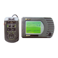
Dickey-John Control Point Operator's Manual (109 pages)
Brand:
Dickey-John
| Category:
Control Systems
| Size: 4 MB
Table of Contents
Table of Contents
2
Safety Notices
6
Introduction
8
Granular Channel Configuration
8
Liquid Channel Configuration
9
Spinner Channel Configuration
9
Product Application Mechanisms
9
Console
10
Switch Module
11
Keyboard
11
Ground Speed Sensor
11
Feedback Sensors
11
Valve Control Devices
12
Hopper Level Sensor (Optional)
12
Harnesses
12
Technical Support
12
System Installation
14
Hardware Kits
14
Standard Hardware Kit Console and Switch Module
14
Optional Hardware Kit for Console Only
14
Console Placement
15
U-Bracket Mounting
15
Console and Switch Module Installation
15
Switch Module to Console Connection
16
Console Mounting
16
Harness Connection
16
Main Harness Connection
17
Checking Operation
18
Start-Up and Familiarization
20
Start-Up Preparation
20
Start-Up Procedure
20
Operate Screen Display Functions
22
Material/Manual Speed Select
23
Accessing the Current Totals Screen
25
Clearing the Current Totals
26
Accessing the Season Totals Screen
27
Using the Blast Button
27
Master Switch in the Unload Position
28
Keyboard Programming
30
Logging Configuration Data
30
Pre-Programming
30
Using the Keyboard and Screens
31
Miscellaneous Menu (F12)
34
Blast Setup
34
Time/Date Setup
35
System Units
35
Serial Port Configuration
36
Service Menu
37
Keyboard Programming Continued
40
Sensor Selection
40
Gate Height Sensor
41
Gate Height Calibration
41
Road Temperature Sensor
42
Temperature Sensor Calibration
43
Air Temperature Sensor
44
Air Temperature Sensor Calibration
45
12V Boom Switched Output
46
Down Pressure Sensor
47
Down Pressure Sensor Calibration
47
Bed Height Sensor
48
Bed Height Sensor Connection
48
Bed Height Sensor Calibration
49
Accessing the Operate Mode (F1)
50
Setting up Granular Configuration (F3)
50
Programming Granular Application Rates (F2)
53
Liquid Configuration Setup (F5)
55
Setting Liquid Configurations
55
Tank Level Sensor Configuration
57
Enabling Tank Level Sensor
58
Tank Empty and Tank Full
58
Tank Alarm
58
Tank Capacity
59
Boom Configuration
60
Programming Liquid Application Rates (F4)
62
Ground Speed Configuration (F7)
66
Ground Speed Calibration (F7-1)
68
Spinner Channel Configuration (F8)
70
Monitor & Reset Accumulators (F9)
72
Reading System Information (F10)
74
Performing System Response (F11)
76
System Calibration
78
Recording Calibration Data
78
Repeating Calibration Runs
78
Maintaining Calibration Accuracy
78
Calibration System Response (F11)
80
Granular System Response Calibration
80
Fine Tuning System Response Constants
82
SYS RSPNS Constant
82
Valv Boost
83
Afilt
83
Proportional Valve Spinner Calibration
83
Granular Materials Calibration (F6)
84
Granular Calibration Fine Tuning
86
Liquid Materials Calibration (F6)
86
Liquid Calibration Fine Tuning
89
Calibrating Spinner Width (F6)
89
Troubleshooting
92
Appendix A Converting Constants
102
Fine Tuning Application
102
Calculating Spreader Constants
103
Calibration Data Record Sheet
104
Warranty
108
Advertisement
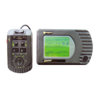
Dickey-John Control Point Operator's Manual (70 pages)
Brand:
Dickey-John
| Category:
Control Systems
| Size: 0 MB
Table of Contents
Chapter 1 - System Description
1
Granular Channel Configuration
1
Product View
1
Liquid Channel Configuration
2
Product Application Mechanism
2
Spinner Channel Configuration
2
System Component Descriptions
3
System Features and Capabilities
3
Ground Speed Sensor
4
Keyboard
4
Switch Module
4
System Block Diagram
4
Actuator Devices
5
Feedback Sensors
5
Harnesses
5
Hopper Level Sensor
5
How to Obtain Technical Support
5
Chapter 2 - Operating Procedures
7
Preparing for Operation
7
Switch Module Controls and Definitions
7
Console Showing Functional Items
8
Starting the System
8
Turn on the Ignition Switch
8
Turn the Console off
8
Change the Target Rate of Either Product Channel
9
Observing the Operate Screen Divisions
9
Operate Screen Showing Product Application
10
Material/Manual Speed Select Screen
11
Screens Available to Operator by Cycling
11
Selecting a Different Dispersal Material
11
Accessoing the Current Totals Screen
12
Current Totals Screen View
12
Returning to the Operate Screen
12
Substituting Manual Speed for Standard Speed Sensor
12
Accessing the Season Totals Screen
13
Clearing the Current Totals
13
Master Switch in the Unload Position
14
Using the Blast Button
14
Chapter 3 - Keyboard Programming
15
Keyboard Layout and Functions
15
Logging Configuration Data
15
Preprogramming
15
Editing a Parameter
16
Function Screen (Top Level)
16
Parameter Screens (Second Level)
16
Using the Keyboard and Screens
16
Programming System from the Keyboard
17
Screen Prompts
17
The Backspace Key
17
Using the Miscellaneous Menu
18
Choosing Displayed Language and Keyboard
19
Configuring RS-232 Port
19
Setting up System Units
19
Accessing the Operate Mode
20
Viewing the Service Menu Items
20
Setting up Granular Configuration
21
Programming Granular Application Rates
23
Configuring Liquid Channel for Prewet Yes/No
25
Setting up Liquid Configuration
25
Configuring Liquid Channel for Pressure
26
Configuring Boom Sections of Liquid Channel
27
Programming Liquid Application Rates
28
Using the Calibration Menu
29
Configuring Ground Speed
30
Configuring the Spinner Channel
31
Monitoring/Resetting Accumulators
32
Reading System Information
33
Chapter 4 - System Calibration
35
Recording Calibration Data
35
Repeating Calibration Runs
35
Calibrating Ground Speed
36
Calibration System Response
37
Fine Tuning System Response Constants
38
Calibrating Proportional Valve Spinner
39
Calibrating Granular Materials
40
Fine-Tuning the Granular Calibration
41
Calibrating Liquid Materials
42
Fine-Tuning the Liquid Calibration
43
Calibrating Spinner Width
44
Maintaining Calibration Accuracy
44
Chapter 5 - System Installation
45
Selecting the Console Location
45
Installing Console and Switch Module
46
Mounting the U-Bracket
46
Connecting Switch Module to Console
47
Laying out the Main Harness
47
Mounting the Console
47
Routing and Connecting the Harnesses
47
Using the Extension Harness
48
Checking Operation
49
Switch Module Cabling
49
System Harness Layout
50
Chapter 6 - System Troubleshooting
51
"Manual Mode" Flashes on Display
52
Console Does Not Power on
52
Auto Inoperative; Unload Operates
53
Corrective Action for Liquid System
53
Displayed APR Fluctuates
54
Displayed APR Responding Slowly
54
Spinner Rotational Speed Incorrect
54
Application Rate Error
55
System Does Not Operate
56
System Wiring Diagram, Console and Cab Harness
58
System Wiring Diagram, Truck Harness and Sensors
59
Adjusting Granular Constants/Adjusting Liquid Constants
61
Adjusting Nozzle Constants
61
Appendix A - Converting Constants
61
Fine Tuning Application
61
Calculating Spreader Constants
62
Adjusting Valve Manually
63
Appendix B - Mechanical Adjustments
63
Valve Coupling View
63
Eliminating Conveyor or Spinner Creep
64
Advertisement
Related Products
Dickey-John C-2000
Dickey-John CSS 110
Dickey-John 47294-0110
Dickey-John 47294-0115
Dickey-John Flex4
Dickey-John Flex4 Pro
Dickey-John IntelliAg
Dickey-John IntelliAg MVT
Dickey-John Categories
Measuring Instruments
Control Systems
Monitor
Test Equipment
Control Unit
More Dickey-John Manuals
Login
Sign In
OR
Sign in with Facebook
Sign in with Google
Upload manual
Upload from disk
Upload from URL