Table of Contents
Advertisement
Quick Links
Advertisement
Table of Contents
Troubleshooting

Related Manuals for Dickey-John Flex4 Pro


Summary of Contents for Dickey-John Flex4 Pro
- Page 1 ® S I N C E 1 9 6 6 FLEX4 PRO ™ PUBLIC WORKS CONTROL SYSTEM FLEX...
-
Page 2: Table Of Contents
Safety Notices ......................1 Disclaimer ..........................1 Introduction ......................3 Features ..........................3 Component Overview ................... 5 Flex4 Pro tablet ........................5 Switch module functions ...................... 8 Rate control module ......................9 Output module ........................11 Miscellaneous components ....................15 Installation ...................... - Page 3 Control module ........................ 131 Output module ......................... 135 Troubleshooting ....................137 Appendix A ......................143 Appendix B Converting Constants..............145 Fine Tuning Application ....................145 Calculating Spreader Constants ..................146 Appendix C ......................147 Flex4 Pro Control System 6010541 Rev A...
-
Page 4: Safety Notices
DISCLAIMER DICKEY-john reserves the right to make engineering refinements or procedural changes that may not be reflected in this manual. Material included in this manual is for informational purposes and is subject to change without notice. - Page 5 OPERATOR’S MANUAL SAFETY NOTICES / 2 Flex4 Pro Control System 6010541 Rev A...
-
Page 6: Introduction
OPERATOR’S MANUAL INTRODUCTION The DICKEY-john Flex4 Pro Control System can simultaneously control both granular and liquid snow and ice removal materials. Separate channels for granular and liquid precisely controls and maintains the desired applications. The flow of material varies automatically in proportion to the changes in ground speed so the application rate remains uniform. - Page 7 OPERATOR’S MANUAL 4 / INTRODUCTION Flex4 Pro Control System 6010541 Rev A...
-
Page 8: Component Overview
OPERATOR’S MANUAL COMPONENT OVERVIEW Components included with the Flex4 Pro Control System: • Flex4 Pro tablet • Flex4 Pro tablet mounting plate, bracket, and hardware • Rate control module • Operator Switch Module • Operator Switch Module mounting bracket and hardware •... - Page 9 -22 degrees F to +160 degrees F (-30 degrees C to +71 degrees C) Humidity: 5% - 95% non-condensing The Flex4 Pro tablet should not be turned on until product temperature stabilization occurs when exposed to different temperature extremes. Cab temperatures should be above 32 degrees for proper operation.
- Page 10 OPERATOR’S MANUAL TABLET CONNECTIONS Two tablet connections on the Flex4 Pro tablet are used. 1. Tablet power cable 2. USB port (connects to Tough Hub) Figure 3 Flex4 Tablet Connections volume power adjustment button USB port ...
-
Page 11: Switch Module Functions
Spread Width Knob adjusts the spinner speed to regulate material spread width. The spread width percentage displays on the console. Pressing the spread width knob also selects a channel to adjust. 8 / COMPONENT OVERVIEW Flex4 Pro Control System 6010541 Rev A... -
Page 12: Rate Control Module
Module that allows for easy hookup and access. 2. Use the enclosure as a template to mark the location of the mounting holes. 3. Drill four 9/32 inch diameter holes where marked. COMPONENT OVERVIEW / 9 Flex4 Pro Control System 6010541 Rev A... - Page 13 4. Mount with the label side of module facing out. Do not mount with the connector facing up (see Caution). Connect any additional adapter harnesses to the module harness. The Rate Control Module harness can accept an extension harnesses or the output harness. 10 / COMPONENT OVERVIEW Flex4 Pro Control System 6010541 Rev A...
-
Page 14: Output Module
Extensions may be used to reach members installed on remote areas of the vehicle. 2. The module can be mounted in the same orientations as the rate control module as illustrated in (Figure 7). COMPONENT OVERVIEW / 11 Flex4 Pro Control System 6010541 Rev A... - Page 15 – Attach to frame using 1/4 x 20 bolts or other fastening devices as illustrated in Figure 8. Do not use the enclosure as a guide when drilling. Do not overtighten nuts as this may damage the mounting tabs on the enclosure. 12 / COMPONENT OVERVIEW Flex4 Pro Control System 6010541 Rev A...
- Page 16 – If necessary, drill mounting holes following the procedure described above. – Securely tighten tie strap. – Install a second tie strap toward the label end of the enclosure for additional support. COMPONENT OVERVIEW / 13 Flex4 Pro Control System 6010541 Rev A...
- Page 17 ATTACHING THE PCECU IN THE CAB The PCECU module is the power management source for the Flex4 Pro Control System. The PCECU mounts inside the cab and attaches to the cab harness. Figure 11 PCECU 7.45” ...
-
Page 18: Miscellaneous Components
The system can function with a variety of electronic and mechanical speedometer sensors, such as hall effect and reluctance sensors. COMPONENT OVERVIEW / 15 Flex4 Pro Control System 6010541 Rev A... - Page 19 A hopper level sensor can be used to trigger an alarm when material falls below the sensor mounting level. VIDEO CAMERA (OPTIONAL) Multiple cameras can be installed in order to monitor dispensed material or provide aid in backing the vehicle. 16 / COMPONENT OVERVIEW Flex4 Pro Control System 6010541 Rev A...
-
Page 20: Installation
(3) switch module stud bolts insert through the bolt holes of the bracket assembly. 6. Secure switch module to the bracket using (3) hex nuts and washers. INSTALLATION / 17 Flex4 Pro Control System 6010541 Rev A... -
Page 21: Ram Mount Bracket Installation
1. Secure bracket to truck cab using 4 SAE screws (included). 2. Insert ball mount into bracket assembly and tighten wing nut. 3. Adjust tablet for ideal viewing by loosening/tightening the wing nut. 18 / INSTALLATION Flex4 Pro Control System 6010541 Rev A... - Page 22 The Accessory Plate should be mounted in an area that avoids possible moisture. Refer to System Harness connection diagrams for attaching these components to the cab harness. Figure 14 Accessories Plate DC Converter USB CAN Adapter RAM Tough Hub INSTALLATION / 19 Flex4 Pro Control System 6010541 Rev A...
- Page 23 The Flex4 Pro tablet must be powered on after the ignition switch is powered on. System harnessing connections include: •...
- Page 24 Adapter Speed Control Sensor Valve Down Pressure Battery INSTALLATION / 21 Flex4 Pro Control System 6010541 Rev A...
- Page 25 Plug the adapter into the USB tough hub mounted to the accessories plate. Figure 18 Cab Harness T o Extension Harness or Rate Control Module Harness Ignition Power connection PC ECU to video USB CAN camera Adapter CAN Terminator Switch to Module battery RAM Mount DC‐DC Converter Hub 22 / INSTALLATION Flex4 Pro Control System 6010541 Rev A...
- Page 26 Ground Speed Remote On/Off Joystick Flex4 Interface cable attaches to any of the Scraper analog 1‐4 connectors. Tank Level Sensor (Analog 2) RoadWatch Temperature Servo 1 Sensor Adapter connects to Liquid the Flex4 Interface cable. Boom Section Servo 2 Auxiliary INSTALLATION / 23 Flex4 Pro Control System 6010541 Rev A...
- Page 27 Extension harness (10 ft) is optional and used when extra length is required to connect with the Rate Control Module harness and the Output Module harness. Figure 21 Extension Harness 24 / INSTALLATION Flex4 Pro Control System 6010541 Rev A...
- Page 28 Drives electric pumps or motors that draw high current (greater than 2 amps). Figure 23 Electric Motor Driver Harness To electric pump Rate Control To PWM channel Module Harness, (liquid or auxiliary) Extension Harness, INSTALLATION / 25 Flex4 Pro Control System 6010541 Rev A...
- Page 29 OPERATOR’S MANUAL 26 / INSTALLATION Flex4 Pro Control System 6010541 Rev A...
-
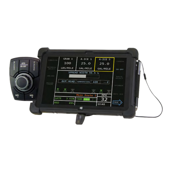
Page 30: Operate Screen Overview
Power button located on the top right edge of the tablet next to the volume adjustment. IMPORTANT: The ignition key should be powered on prior to the Flex4 Pro tablet. The Operate screen has five main structured areas to display button selections and operation functions that include: 1. - Page 31 (3) CONVEYOR When enabled, a left/right conveyor symbol and a front/rear conveyor symbol provides current position and can be changed by pressing the respective buttons. 28 / OPERATE SCREEN OVERVIEW Flex4 Pro Control System 6010541 Rev A...
-
Page 32: Display Settings (Camera/Display/Alarms)
Increase/Decrease buttons are pressed. – The Alarm Volume bar graph indicates the volume level for the audible alarm. An empty bar graph indicates the lowest volume; OPERATE SCREEN OVERVIEW / 29 Flex4 Pro Control System 6010541 Rev A... - Page 33 Press again to return to the night mode setting. Figure 26 Day and Night Mode Screens Day Mode Night Mode 30 / OPERATE SCREEN OVERVIEW Flex4 Pro Control System 6010541 Rev A...
-
Page 34: Operation
IMPORTANT: The system should be programmed and calibrated before spreading material. It is recommended to wait before powering on the Flex4 Pro tablet until temperature stabilization occurs between the tablet and truck cab, especially when exposed to cold to hot temperature extremes. -
Page 35: Pre-Operating Checklist
The selected channel is highlighted in yellow. 2. With the selected channel highlighted, press either the Rate (-) or Rate (+) until the desired rate displays. 32 / OPERATION Flex4 Pro Control System 6010541 Rev A... -
Page 36: Blast
Blast Setup screen. If a predefined time interval has been set to zero, Blast must be turned off manually by pressing the Blast button again. OPERATION / 33 Flex4 Pro Control System 6010541 Rev A... -
Page 37: Pause
2. To disable, press the Pause button again. An alarm sounds indicating Pause is disabled and will disappear on the display. Figure 31 Pause Feature Enabled CH ROUTE SELECT RIVER SPINNER OGIN ANTI‐ICE 34 / OPERATION Flex4 Pro Control System 6010541 Rev A... -
Page 38: Material Selection
4. When selected, press the Back button to return to the Operate screen. Figure 32 Material Selection CH CH ROUTE SELECT DRIVER USER SPINNER LOGIN HELP ANTI‐ICE LIQUID GRANULAR AUX S OPERATION / 35 Flex4 Pro Control System 6010541 Rev A... -
Page 39: Unload Material
Selected materials for removal displays at center of screen, i.e. “Salt Selected”. 4. Press the Start button to begin unload. 5. Press the Stop button when unload is complete. 36 / OPERATION Flex4 Pro Control System 6010541 Rev A... - Page 40 OPERATOR’S MANUAL Figure 34 Unloading a Material START STOP Ensure the area is clear prior to unloading to avoid possible injury. OPERATION / 37 Flex4 Pro Control System 6010541 Rev A...
-
Page 41: Manual Ground Speed Override
IMPORTANT: The Pause button is functional in manual mode however miles driven during Pause mode will not be added to total miles driven while operating with manual ground speed enabled. 38 / OPERATION Flex4 Pro Control System 6010541 Rev A... -
Page 42: Automatic Manual Control Channel Override
CH MANUAL MANUAL OUTE SELECT 0.0 0.0 SPINNER SPINNER LOGIN ANTI‐ICE ANTI‐ICE CH MANUAL MANUAL OUTE SELECT 13.0 550 DRIVER SPINNER LOGIN ANTI‐ICE OPERATION / 39 Flex4 Pro Control System 6010541 Rev A... -
Page 43: Driver Login
Operate screen with route name listed. 3. To remove the route from the Operate screen, return to the Route Select screen and press the No Route button. 40 / OPERATION Flex4 Pro Control System 6010541 Rev A... -
Page 44: Boom Section Control
NOTE: Refer to page 66 to enable boom section control feature. Boom Section Control Button indicates action to occur when pressed OPERATION / 41 Flex4 Pro Control System 6010541 Rev A... -
Page 45: Anti-Ice Feature
Output Module screen can be monitored and controlled at the Operate screen. Front/Rear Conveyor • The Front/Rear Conveyor button toggles between front and rear operation. A graphic indicates the current active state. 42 / OPERATION Flex4 Pro Control System 6010541 Rev A... - Page 46 Figure 43 Gate Increase/Decrease Buttons Left/Right Spinner • Left/Right Spinner button toggles between activating the left spinner, right spinner, or both left and right spinner. Figure 44 Left/Right Spinner LEFT RIGHT OPERATION / 43 Flex4 Pro Control System 6010541 Rev A...
-
Page 47: Hydraulic Accessory Tool Operation
Total time spent spreading granular, spraying liquid, and blasting • Miles (km), tons (metric/English), and gallons (liters) spread while in Pause mode • Trip Log indicates total miles driven in Operate mode 44 / OPERATION Flex4 Pro Control System 6010541 Rev A... - Page 48 Operational Totals screen. Current and Route totals are clearable at this screen, if the capability is enabled at F12 Operational Totals. Figure 46 Total Screen 1 4 5 2 6 3 7 OPERATION / 45 Flex4 Pro Control System 6010541 Rev A...
- Page 49 OPERATOR’S MANUAL 46 / OPERATION Flex4 Pro Control System 6010541 Rev A...
-
Page 50: Flex4 Pro Programming
A keyboard is required to program and calibrate the system. The keyboard is removed after programming is complete. System will not allow entry of setup menus, calibration, or configuration without a keyboard attached. IMPORTANT: After plugging in the keyboard, the Flex4 Pro tablet screen must be touched first before the keyboard becomes active and usable. -
Page 51: Keyboard Functions
1. Press Enter to open a text window on the screen to display all possible selections. 2. Use the Up/Down Arrow buttons to highlight and select the desired parameter. 3. Press Enter to accept. 48 / FLEX4 PROTM PROGRAMMING Flex4 Pro Control System 6010541 Rev A... - Page 52 FLEX4 PROTM PROGRAMMING / 49 Flex4 Pro Control System 6010541 Rev A...
- Page 53 50 / FLEX4 PROTM PROGRAMMING Flex4 Pro Control System 6010541 Rev A...
- Page 54 FLEX4 PROTM PROGRAMMING / 51 Flex4 Pro Control System 6010541 Rev A...
- Page 55 OPERATOR’S MANUAL 52 / FLEX4 PROTM PROGRAMMING Flex4 Pro Control System 6010541 Rev A...
-
Page 56: System Programming
OPERATOR’S MANUAL SYSTEM PROGRAMMING The Flex4 Pro Control system has configuration screens to enter user-defined rates, limits, and parameters for regulating system product application. A keyboard is required for programming. Four channels are available for material and spinner control: NOTE: After plugging in the keyboard,... - Page 57 Granular and L iquid Anti‐Ice channels are OFF ON 54 / SYSTEM PROGRAMMING Flex4 Pro Control System 6010541 Rev A...
-
Page 58: Granular Channel Setup (F2)
NOTE: Calibration Gate Height only appears on this screen when Granular Channel Setup enabled and configured at the Accessory Sensors (F9) screen. RATE METHOD STEP METHOD SYSTEM PROGRAMMING / 55 Flex4 Pro Control System 6010541 Rev A... -
Page 59: Granular Rate Setup
In either case, an alarm activates. The Gate Height should be checked and set at the granular calibration it was ran for on that granular channel. 56 / SYSTEM PROGRAMMING Flex4 Pro Control System 6010541 Rev A... - Page 60 Blast button is pressed during operation. % increase or decrease, based Figure 53 off the target rate, exceeds the Step Method Screen maximum or minimum rate limits set. SYSTEM PROGRAMMING / 57 Flex4 Pro Control System 6010541 Rev A...
- Page 61 (F10) System Setup screen. When the Blast Speed is set to zero, blasting cannot be initiated when the vehicle is stopped. 58 / SYSTEM PROGRAMMING Flex4 Pro Control System 6010541 Rev A...
-
Page 62: Granular Configuration (F2)
Decrease buttons are used to increase/decrease the hydraulic flow to the accessory tool and a PWM percentage on the Operate screen indicates the PWM signal sent to the hydraulic valve. SYSTEM PROGRAMMING / 59 Flex4 Pro Control System 6010541 Rev A... - Page 63 Selection of the four materials that are configurable for the channel. SENSOR CONSTANT Sensor Constant establishes the number of pulses for one revolution of the application rate sensor. If a standard DICKEY-john application rate sensor is used, the value should be set to 360.0. SPREADER CONSTANT The Spreader Constant displayed value is viewable only and indicates the current setting.
- Page 64 Calibration Gate Height only displays if enabled as an accessory sensor at the (F9) Accessory Sensor screen. This value is viewable only and indicates the current setting. The value automatically adjusts when a granular calibration is performed. SYSTEM PROGRAMMING / 61 Flex4 Pro Control System 6010541 Rev A...
-
Page 65: Liquid Channel Setup (F3)
Liquid Channel Setup Screen LIQ 1 LIQ 2 Boom selection LIQ 3 only displays LIQ 4 when a channel is set for liquid or anti‐ice application. 62 / SYSTEM PROGRAMMING Flex4 Pro Control System 6010541 Rev A... -
Page 66: Liquid Rate Setup
42.1 gal/ac 0.825 gal/ac 57.8 ANTI‐ICE RATES A‐ICE 1 gal/mile PREWET 1 PREWET 1 gal/ton 29981.75 gal/ton 5.00 gal/ton 0.500 gal/ton 25.5 gal/ton 0.500 gal/ton 50.0 SYSTEM PROGRAMMING / 63 Flex4 Pro Control System 6010541 Rev A... - Page 67 4. Enter a minimum application rate limit for this channel. 5. Enter a maximum application rate limit for this channel. 6. Enter an Increase/Decrease Step value that sets the increase/ decrease rate. 64 / SYSTEM PROGRAMMING Flex4 Pro Control System 6010541 Rev A...
- Page 68 To select the Rate Method: 1. Highlight the Step method selection box and press the Enter key on the keyboard. 2. Select No and press the Enter key again. SYSTEM PROGRAMMING / 65 Flex4 Pro Control System 6010541 Rev A...
-
Page 69: Boom Configuration (Liquid/Anti-Ice)
A total of 6 boom sections can be controlled by the system. A DICKEY-john output module must be installed to support boom control. To assign Boom Sections: 1. - Page 70 FUNCTION Control NOTE: Contact DICKEY-john Technical Support at 1-800-637-3302 to Boom sections are controlled by a DICKEY-john output module allowing order a DICKEY-john output sections to be turned on and off at the Operate screen with assigned module. section buttons.
- Page 71 1. At the F4 Aux S screen, use the Up or Down Arrow keys on the keyboard to select and highlight ”Spinner”. 2. Press “1” to enter parameter values per below definition. 68 / SYSTEM PROGRAMMING Flex4 Pro Control System 6010541 Rev A...
- Page 72 Blast is pressed regardless of any adjustment to the spread width knob. A Blast Rate percentage set at zero places no constraints on the maximum spinner speed when using the spread width knob. SYSTEM PROGRAMMING / 69 Flex4 Pro Control System 6010541 Rev A...
- Page 73 Operate screen. A full bar graph indicates that the maximum GSRS speed has been exceeded in mph/kph. No alarm is associated with this constant. Displays only if Ground Speed Related is YES. 70 / SYSTEM PROGRAMMING Flex4 Pro Control System 6010541 Rev A...
-
Page 74: Auxiliary Control Channel Configuration (F5)
Refer to the Granular Configuration (F2) and Liquid Configuration (F3) sections for parameter definition and setup instructions. Press the Calibration (F6) key to initiate channel calibration. Figure 63 Auxiliary Control Channel Screen Flex4 Pro Control System SYSTEM PROGRAMMING / 71 6010541 Rev A... -
Page 75: Accessory Sensors (F9)
• Down pressure Two digital accessory sensors can be enabled at one time. In addition to configuring accessory sensors, an installed DICKEY-john joystick’s active position can be viewed on the Operate screen when enabled at this screen. To enable Accessory Sensors: 1. - Page 76 If the gate height is enabled and calibrated, all of the desired granular materials that are enabled must be recalibrated through a material drop test. If enabled materials are not calibrated, the system will alarm. SYSTEM PROGRAMMING / 73 Flex4 Pro Control System 6010541 Rev A...
- Page 77 6. After values are entered, press C to begin the calibration procedure. Calibration lasts approximately 10-20 seconds. 7. Press “D” when done. 74 / SYSTEM PROGRAMMING Flex4 Pro Control System 6010541 Rev A...
- Page 78 Surface Patrol temperature sensor must be disconnected and the Flex4 Interface cable and the DICKEY-john temperature sensor adapter connected to the main harness for successful calibration. If the interface cable and the DICKEY-john temperature sensor adapter is disconnected when the calibration is performed, an error screen displays.
- Page 79 Patrol temperature sensor must be disconnected and the DICKEY-john temperature sensor adapter connected to the main harness for successful calibration. If the DICKEY-john temperature sensor adapter is disconnected when calibration is performed, an error screen displays. IMPORTANT: The Road Watch...
- Page 80 150 gallons. The alarm sounds for the first five seconds and text will flash until the condition is cleared or another alarm sounds. Figure 69 Tank Level Sensor PRESS C TO CAPTURE VOLTAGE SYSTEM PROGRAMMING / 77 Flex4 Pro Control System 6010541 Rev A...
- Page 81 8. Enter a down pressure alarm percentage to warn when the down pressure is within the specified percentage of reaching the maximum down pressure limit. Figure 70 Down Pressure 78 / SYSTEM PROGRAMMING Flex4 Pro Control System 6010541 Rev A...
- Page 82 The alarm should only be used as a secondary convenience indicator. The operator assumes all risk in using this feature. DICKEY-john assumes no responsibility for alarm failure to indicate an unsafe operating height. Bed Height status appears on Operate screen as: BED ...
- Page 83 12V is sensed; the camera automatically appears on the display. ACTIVE LEVEL (Digital or Camera) Active level sets the sensor output signal as either Ground or 12V to sense the sensor as on or off. 80 / SYSTEM PROGRAMMING Flex4 Pro Control System 6010541 Rev A...
- Page 84 A user-defined name that identifies sensor type and displays on the Operate screen providing sensor status (7 character maximum). CONSTANT (Frequency) Constant establishes the number of pulses for one revolution of the application rate sensor. SYSTEM PROGRAMMING / 81 Flex4 Pro Control System 6010541 Rev A...
- Page 85 The system shutdowns automatically when High and Low Shutdown is enabled and the alarm condition is met as defined in High and Low Alarm Limits. Both High and Low Shutdown functionality is independent of each other. 82 / SYSTEM PROGRAMMING Flex4 Pro Control System 6010541 Rev A...
- Page 86 OPERATOR’S MANUAL JOYSTICK LABELS When a DICKEY-john joystick is installed, joystick labels can be created to indicate functions that are enabled or active. Joystick function appears on Operate screen as: SCRAPER To create Joystick Control Names: 1. At the (F9) Accessory menu screen, press 7 on the keyboard to display the Joystick Labels screen.
-
Page 87: System Setup (F10)
2. At the System Setup screen, press the respective item number to open a menu item. Figure 75 System Setup Screen BLAST SETUP 1. Press 1 on the keyboard to select Blast Setup. Figure 76 Blast Setup Screen 84 / SYSTEM PROGRAMMING Flex4 Pro Control System 6010541 Rev A... -
Page 88: Date And Time
3. At the Current Time input box, highlight the digits to change and type in the time. 4. At the Current Date input box, highlight the digits to change and type in the date. Figure 77 Date and Time Screen SYSTEM PROGRAMMING / 85 Flex4 Pro Control System 6010541 Rev A... -
Page 89: Units And Language
2. Select Yes to enable metric as the unit of measurement. Default is set to English. 3. The current language setting of English cannot be adjusted. Figure 78 Units and Language Screen 86 / SYSTEM PROGRAMMING Flex4 Pro Control System 6010541 Rev A... -
Page 90: Service
1. At the (F10) System Menu screen, press 4 on the keyboard to select the Service menu screen. SOFTWARE VERSION 1. Press 1 at the Service screen to display the system’s installed software version. Figure 79 Software Version Screen SYSTEM PROGRAMMING / 87 Flex4 Pro Control System 6010541 Rev A... - Page 91 This mode alerts with a periodic warning message on the Main Work screen informing the that this mode is on and it should be turned off during regular operation. Figure 81 Service Keyboard Mode Screen 88 / SYSTEM PROGRAMMING Flex4 Pro Control System 6010541 Rev A...
-
Page 92: Troubleshooting
IMPORTANT: It is recommended that these parameters not be modified as any changes could affect performance. Contact DICKEY-john Technical Support at 1-800-637-3302 for assistance. 1. At the (F10) System menu screen, press 5 on the keyboard to display the Troubleshooting screen. - Page 93 GPS Sensor screen. 2. Select Yes to indicate a GPS sensor is installed. 3. Select Yes to log GPS position and coordinates by event. Figure 83 GPS Sensor Screen 90 / SYSTEM PROGRAMMING Flex4 Pro Control System 6010541 Rev A...
-
Page 94: Output Module Setup (F11)
Operate screen. Spinner direction can be left, right, or both can be on at the same time. The active position of the conveyor displays on the Operate screen. SYSTEM PROGRAMMING / 91 Flex4 Pro Control System 6010541 Rev A... - Page 95 The PWM percentage entered determines the PWM signal level that is sent to the electric actuated cylinder when the gate increase or decrease button is pressed from the main Flex4 Pro tablet Operate screen. The higher the PWM signal is set, the faster the gate opens or closes.
-
Page 96: Data Logging (F12)
– Up to 275 alarms can be recalled. – Each alarm occurrence can have up to 6 occurrences of the alarm tagged with a date and time stamp. SYSTEM PROGRAMMING / 93 Flex4 Pro Control System 6010541 Rev A... - Page 97 1. At the Data Logging screen, press 2 to access the Truck ID screen and enter desired ID. Figure 87 Truck ID Screen Flex4 Pro Control System 94 / SYSTEM PROGRAMMING 6010541 Rev A...
-
Page 98: Driver Setup
Driver Login is set at NO and a driver passcode is entered at the Driver ID Configuration screen, login is available but will not automatically display on power up. SYSTEM PROGRAMMING / 95 Flex4 Pro Control System 6010541 Rev A... - Page 99 After Driver ID Configuration is setup, the Driver Login/Logout screen appears requiring the driver’s personal passcode before gaining access to the Operate screen. Refer to the Operation section for additional information. 96 / SYSTEM PROGRAMMING Flex4 Pro Control System 6010541 Rev A...
- Page 100 Returning to the Operate screen completes that setup session and requires re-entry of the passcode again to enter setup screens. Disabling the passcode setting resets the system allowing full access to configuration screens. SYSTEM PROGRAMMING / 97 Flex4 Pro Control System 6010541 Rev A...
- Page 101 After Routes are setup, a Route button is enabled at the Operate screen to access the Route Selection screen. Refer to the Operation section for additional information. Figure 91 Route Configuration and Selection Screens 98 / SYSTEM PROGRAMMING Flex4 Pro Control System 6010541 Rev A...
- Page 102 (metric/English) and gallons (liters) spread for each product. PAUSE MODE- total miles driven in Pause mode is logged in miles (km), tons (metric/English), and gallons (liters) spread for each product. SYSTEM PROGRAMMING / 99 Flex4 Pro Control System 6010541 Rev A...
- Page 103 OPERATOR’S MANUAL Figure 92 NOTE: Season totals can only be cleared using the keyboard at Operational Totals Screen the Operational Totals screen. 100 / SYSTEM PROGRAMMING Flex4 Pro Control System 6010541 Rev A...
- Page 104 To view Lifetime Totals: 1. At the (F12) Data Logging screen, press 6 on the keyboard to access the Lifetime Totals screen. Figure 93 Lifetime Totals Screen SYSTEM PROGRAMMING / 101 Flex4 Pro Control System 6010541 Rev A...
- Page 105 OPERATOR’S MANUAL 102 / SYSTEM PROGRAMMING Flex4 Pro Control System 6010541 Rev A...
-
Page 106: Calibrations
3. When the calibration is complete the results automatically record in the proper locations. Press “C” to automatically begin drop test or press “D” to return to the Calibration screen. CALIBRATIONS / 103 Flex4 Pro Control System 6010541 Rev A... -
Page 107: Recording Calibration Data
Calibration Data Record sheets included with this manual. If console replacement is necessary, export system files to a USB memory device for import to another system. 104 / CALIBRATIONS Flex4 Pro Control System 6010541 Rev A... -
Page 108: Maintaining Calibration Accuracy
Valve Boost increases system response only at startup to quickly start system spreading. The value does not affect stability when operating at the target APR and does not normally require adjustment. CALIBRATIONS / 105 Flex4 Pro Control System 6010541 Rev A... -
Page 109: Granular Drop Test Calibration
IMPORTANT: If a gate height sensor is installed, verify the gate height sensor selection is enabled at the (F9) Accessory Sensor screen before performing the drop test. 106 / CALIBRATIONS Flex4 Pro Control System 6010541 Rev A... - Page 110 11. Average the results and enter the average as the final spreader constant. 12. Record the material’s spreader constants on the Calibration Data Records sheets at the rear of this manual. 13. Repeat this procedure for each granular material used. CALIBRATIONS / 107 Flex4 Pro Control System 6010541 Rev A...
- Page 111 OPERATOR’S MANUAL Figure 95 Granular Drop Test Procedure 108 / CALIBRATIONS Flex4 Pro Control System 6010541 Rev A...
-
Page 112: Liquid Drop Test Calibration (F6)
– For pressure-based anti-ice systems, a target pressure must be entered. This should be the nozzle manufacturer’s rating pressure typically 40 psi (2.75 bar). – If running pressure, ensure booms are drained prior to running Offset CALIBRATIONS / 109 Flex4 Pro Control System 6010541 Rev A... - Page 113 12. Average the results and enter the average as the final K Factor constant. 13. Record the material’s K Factor constants on the Calibration Data Records sheets at the rear of this manual. 14. Repeat this procedure for each liquid material used. 110 / CALIBRATIONS Flex4 Pro Control System 6010541 Rev A...
- Page 114 This constant can be manually entered on the Liquid Configuration screen. A liquid calibration routine can also be repeated to correct this type of APR error. CALIBRATIONS / 111 Flex4 Pro Control System 6010541 Rev A...
-
Page 115: Auxiliary System Response And Drop Test
Figure 97 Spinner System Response Screens (LIQUID/GRANULAR 5‐8) (LIQUID/GRANULAR 5‐8) AUX S SYSTEM RESPONSE (LIQUID/GRANULAR 9‐12) AUX S DROP TEST (LIQUID/GRANULAR 9‐12) SPINNER S YSTEM R ESPONSE SPINNER S PREAD W IDTH 112 / CALIBRATIONS Flex4 Pro Control System 6010541 Rev A... - Page 116 OPERATOR’S MANUAL Figure 98 Spinner System Response Screens CALIBRATIONS / 113 Flex4 Pro Control System 6010541 Rev A...
- Page 117 Spread Width popup window. This process is required an additional 4 times to calculate an average that appears on the screen each time another calibration is ran. 114 / CALIBRATIONS Flex4 Pro Control System 6010541 Rev A...
- Page 118 CALIBRATIONS / 115 Flex4 Pro Control System 6010541 Rev A...
- Page 119 MANUAL SPEED ACCESS Allows the operator to activate the manual speed mode when necessary. Manual speed can be enabled and disabled at the Material Selection screen. 116 / CALIBRATIONS Flex4 Pro Control System 6010541 Rev A...
- Page 120 GROUND SPEED CONSTANT Determines the number of pulses received from the ground speed sensor per mile of travel. If unknown, the value automatically calculates during a ground speed calibration. CALIBRATIONS / 117 Flex4 Pro Control System 6010541 Rev A...
- Page 121 Ground speed calibration establishes a ground speed constant(s) for the vehicle. The constant is determined by counting the number of ground speed sensor pulses generated in a distance of one mile. Figure 102 Ground Speed Calibration Screens 118 / CALIBRATIONS Flex4 Pro Control System 6010541 Rev A...
- Page 122 8. To ensure accuracy, repeat the calibration procedure three times and to stop. average the results. Enter the average value. 9. Record the ground speed constant on the Calibration Data Records sheets at the rear of this manual. CALIBRATIONS / 119 Flex4 Pro Control System 6010541 Rev A...
- Page 123 OPERATOR’S MANUAL 120 / CALIBRATIONS Flex4 Pro Control System 6010541 Rev A...
-
Page 124: Import/Export Data Files
Export to USB confirmation screen displays the file name that contains the configuration files. 5. Press the Export Now button. 6. A Data Export Done screen indicates file transfer is complete. IMPORT/EXPORT DATA FILES / 121 Flex4 Pro Control System 6010541 Rev A... -
Page 125: Export Log Data Files
Log data files can be imported to a reporting software tool to create truck fleet reports. To export Log Data Files: 1. Insert USB memory device into USB port below the Operator Switch Module. 122 / IMPORT/EXPORT DATA FILES Flex4 Pro Control System 6010541 Rev A... - Page 126 EXPORT LOGGED DATA BACK EXPORT TO USB LOGGED DATA FILE NAME: Flex4_Truck ID_2016-07-29. EXPORT & EXPORT CLEAR TOTALS Logged Data Files Export in Progress BACK DATA EXPORT DONE PLEASE REMOVE STORAGE DEVICE AND CHECK THAT DATA WAS EXPORTED CORRECTLY WOULD YOU LIKE TO CLEAR CURRENT TOTALS? BACK PRESS BACK TO EXIT AND PRESERVE TOTALS IMPORT/EXPORT DATA FILES / 123 Flex4 Pro Control System 6010541 Rev A...
- Page 127 Each time an export occurs the file name is saved with the Flex4 name identifier, the Truck ID, date of the download, and time of the download FILE STRUCTURE: Flex4_DataFolder/Flex4_TruckID_Date_Time EXAMPLE: Flex4_DataFolder/Flex4_42067_2011-09-14_15-00-39 124 / IMPORT/EXPORT DATA FILES Flex4 Pro Control System 6010541 Rev A...
-
Page 128: Import Configuration Files
SELECT FILE FROM BELOW LIST Dj_Flex4_Settings_42067.xml IMPORT FILE BACK IMPORT SETTINGS SELECT DATA TO BE IMPORTED CONFIGURATIONS ROUTE NAMES DRIVER NAMES PASSCODES IMPORT BACK USE TERMINAL KEYS TO SELECT DATA DATA IMPORT DONE BACK IMPORT/EXPORT DATA FILES / 125 Flex4 Pro Control System 6010541 Rev A... - Page 129 6. Press the Reboot button to turn the system off and on again to accept imported data. Figure 107 Rebooting the Tablet DATA DATA DATA IMPORT IMPORT IMPORT DONE DONE DONE YOU MUST REBOOT THE TERMINAL TO SAVE REBOOT ALL IMPORTED DATA SYSTEM BACK BACK BACK 126 / IMPORT/EXPORT DATA FILES Flex4 Pro Control System 6010541 Rev A...
-
Page 130: Capture Screen Shot
1. Insert USB memory device. 2. At the desired screen, press and hold until a gray box appears underneath finger press. 3. Remove USB memory device. Figure 108 Screen Shot CAPTURE SCREEN SHOT / 127 Flex4 Pro Control System 6010541 Rev A... - Page 131 OPERATOR’S MANUAL 128 / CAPTURE SCREEN SHOT Flex4 Pro Control System 6010541 Rev A...
-
Page 132: Diagnostics
• Output module (added accessories) PERFORM A DIAGNOSTICS CHECK (F7) NOTE: After plugging in the keyboard, the Flex4 Pro tablet screen To perform a diagnostics check, vehicle ground speed must be zero and must be touched first before the manual ground speed must be enabled at the appropriate ground speed keyboard becomes active and setting. - Page 133 2. At the selected Diagnostics screen, press the switch module Auto On/ Off button to On to display system readings. Figure 110 Main Diagnostic Screen PCECU 130 / DIAGNOSTICS Flex4 Pro Control System 6010541 Rev A...
-
Page 134: Display Pcecu
Control Module Diagnostics screen. 2. Select the appropriate material (Granular, Liquid, Aux, Aux S), spinner, or accessory sensor to perform the relevant diagnostic check. Figure 112 Control Module Diagnostics Screen DIAGNOSTICS / 131 Flex4 Pro Control System 6010541 Rev A... - Page 135 Voltage readings from the truck battery are displayed for the following: – Solenoid Power – Solenoid Ground – ECU Power – ECU Ground 132 / DIAGNOSTICS Flex4 Pro Control System 6010541 Rev A...
- Page 136 – Solenoid Power (voltage from battery to solenoid relays) – Solenoid Ground (voltage from battery to solenoid relays) – ECU Power (voltage present at rate controller module) – ECU Ground (voltage present at rate controller module) DIAGNOSTICS / 133 Flex4 Pro Control System 6010541 Rev A...
- Page 137 – Solenoid Ground (voltage from battery to solenoid relays) – ECU Power (voltage present at rate controller module) – ECU Ground (voltage present at rate controller module) Figure 114 Accessory Sensor Diagnostics AUX S AUX S 134 / DIAGNOSTICS Flex4 Pro Control System 6010541 Rev A...
-
Page 138: Output Module
DIAGNOSTICS / 135 Flex4 Pro Control System 6010541 Rev A... - Page 139 OPERATOR’S MANUAL 136 / DIAGNOSTICS Flex4 Pro Control System 6010541 Rev A...
-
Page 140: Troubleshooting
OPERATOR’S MANUAL TROUBLESHOOTING Error messages display when an abnormal event occurs. For any failure that persists, contact DICKEY-john Technical Support at 1-800-637-3302. TROUBLESHOOTING / 137 Flex4 Pro Control System 6010541 Rev A... - Page 141 6. Check for insufficient hydraulic oil flow at normal engine RPM. 7. Check spreader valve, electrical connections to the valve coil, resistance of the coils (See manufacturers specifications), and verify voltage from control console. 138 / TROUBLESHOOTING Flex4 Pro Control System 6010541 Rev A...
- Page 142 Temperature has dropped below alarm threshold. 1. Adjust alarm setting. 2. Check sensor. 1. Adjust alarm setting. Air Temp Below Alarm Value Temperature has dropped below alarm threshold. 2. Check sensor. TROUBLESHOOTING / 139 Flex4 Pro Control System 6010541 Rev A...
- Page 143 3. Inspect module for damage and replace if necessary. Solenoid Voltage with Solenoid voltage is too high and the control system 1. Voltage issue must be corrected before control Control Shutdown has shutdown. can resume. 140 / TROUBLESHOOTING Flex4 Pro Control System 6010541 Rev A...
- Page 144 1. Service Keyboard Mode is enabled at the F10 speed is above 0 and the master switch is OFF. System screen. Warning continues to displays until the function is disabled. TROUBLESHOOTING / 141 Flex4 Pro Control System 6010541 Rev A...
- Page 145 OPERATOR’S MANUAL 142 / TROUBLESHOOTING Flex4 Pro Control System 6010541 Rev A...
-
Page 146: Appendix A
Single Granular, Spinner GRANULAR ENABLED LIQUID NOT USED NOT USED AUX-S SPINNER NOT USED NOT USED Single Granular, Pre-Wet, Spinner GRANULAR ENABLED LIQUID PRE-WET PWM/SERVO AUX-S SPINNER NOT USED NOT USED Flex4 Pro Control System APPENDIX A / 143 6010541 Rev A... - Page 147 GRANULAR ENABLED LIQUID LIQUID ANTI-ICE PWM/SERVO AUX-S SPINNER NOT USED NOT USED Tow Plow (2 Granular, 2 Pre-Wet) GRANULAR ENABLED LIQUID LIQUID PRE-WET PWM/SERVO AUX-S GRANULAR LIQUID PRE-WET PWM/SERVO 144 / APPENDIX A Flex4 Pro Control System 6010541 Rev A...
-
Page 148: Appendix B Converting Constants
EXAMPLE: If K-FACTOR is 1,000 and Target APR is 10 GAL/MILE, but Actual APR is known to be 9.5 GAL/MILE, adjust K-FACTOR using the above formula: New K-FACTOR = 1000 x = 1053 APPENDIX B CONVERTING CONSTANTS / 145 Flex4 Pro Control System 6010541 Rev A... -
Page 149: Calculating Spreader Constants
1. V-Box spreaders have a different SPR CON for each gate setting. 2. The number of pulses per revolution for several Dj shaft sensors are: 360 for p/n 46436-017X (standard DICKEY-john shaft sensor). 60 for p/n 10844-000X 180 for p/n 464361500S1... - Page 150 6010541 Rev A...
-
Page 151: Appendix C
OPERATOR’S MANUAL APPENDIX C APPENDIX C / 147 Flex4 Pro Control System 6010541 Rev A... - Page 152 FLEX4 PRO ™ PUBLIC WORKS CONTROL SYSTEM DICKEY-john, and the DICKEY-john Logo are registered trademarks, and Flex4 is a ® trademark of DICKEY-john. S I N C E 1 9 6 6 P/N 6010541 Rev A...
Need help?
Do you have a question about the Flex4 Pro and is the answer not in the manual?
Questions and answers