Table of Contents
Advertisement
Quick Links
TABLE OF CONTENTS
Safety Notices ...................................................................................................... 1
System Overview ................................................................................................. 3
Virtual Terminal (VT).......................................................................................................... 3
Master Switch .................................................................................................................... 4
Working Set Master (WSMT) Module (Planter Drill Control).............................................. 4
Working Set Member (WSMB) Module (optional).............................................................. 5
Implement Lift Switch (optional)......................................................................................... 5
CAN Terminators ............................................................................................................... 5
System Requirements ......................................................................................... 7
Performance Features ....................................................................................................... 7
Compatibility ...................................................................................................................... 8
Installation ............................................................................................................ 9
Virtual Terminal.................................................................................................................. 9
Master Switch .................................................................................................................... 9
Working Set Master (WSMT) Module .............................................................................. 10
Working Set Member (WSMB) Module............................................................................ 12
Cab Harness Connections ............................................................................................... 15
Sensor Installation ........................................................................................................... 21
Seed Sensors.................................................................................................................................. 21
Hopper Level Sensors..................................................................................................................... 23
RPM/Fan Sensors........................................................................................................................... 23
Air Pressure Sensors ...................................................................................................................... 23
System Modes.....................................................................................................25
User Level Access ........................................................................................................... 25
Operate Mode .................................................................................................................. 25
Available Buttons in Operate Mode ................................................................................. 26
Setup/Configuration Mode ............................................................................................... 28
Available Buttons in Setup Mode ..................................................................................... 28
Planter Fill Disk ............................................................................................................................... 28
Row Monitor Setup.......................................................................................................................... 28
Control Setup .................................................................................................................................. 28
Speed Set ....................................................................................................................................... 29
Diagnostics...................................................................................................................................... 29
Alarm Log........................................................................................................................................ 29
System Accumulators ..................................................................................................................... 29
Module Configuration ...................................................................................................................... 29
Screen Configuration ...................................................................................................................... 29
Planter Output Module (POM) Configuration (optional) .................................................................. 29
Configuration................................................................................................................................... 29
User Levels......................................................................................................... 31
User Level 1 Operator (Basic View)................................................................................. 31
Change Operator Level to OEM/Dealer Level ................................................................. 32
IntelliAg PDC User 2 & 3
11001-1509A-201105
i
Advertisement
Table of Contents

Related Manuals for Dickey-John IntelliAg


Summary of Contents for Dickey-John IntelliAg
-
Page 1: Table Of Contents
Module Configuration ........................29 Screen Configuration ........................29 Planter Output Module (POM) Configuration (optional) ..............29 Configuration........................... 29 User Levels......................31 User Level 1 Operator (Basic View)................. 31 Change Operator Level to OEM/Dealer Level ..............32 IntelliAg PDC User 2 & 3 11001-1509A-201105... - Page 2 Row Width ............................50 On/Off Pattern ..........................51 Row Fail Rate ..........................51 Material Setup Constants - RPM Control ................ 52 Target Rate............................52 Max Rate ............................52 Min Rate ............................52 Inc/Dec % ............................52 IntelliAg PDC User 2 & 3 11001-1509A-201105...
- Page 3 Drive Frequency..........................81 Input Filter ............................81 Sensor Constant ..........................81 Master Switch Off..........................81 Ramp Up/Down..........................81 Disable Control On Control Failure Alarm ..................82 Valve Calibration - RPM Control ..................83 IntelliAg PDC User 2 & 3 11001-1509A-201105...
- Page 4 Ground Fail Alarm Delay ....................... 107 Precharge Ground Speed......................107 Flush Enable Speed ........................107 Implement Lift ..........................107 Ground Speed Calibration ..................... 108 10” VT Aux Input/Function Assignment ................. 109 5” VT Aux Input/Function Assignment ................110 IntelliAg PDC User 2 & 3 11001-1509A-201105...
- Page 5 RPM Scan ............................. 125 Channel 1-4 Product Level .................... 125 Hopper Level Status Scan ..................... 125 Boom Status ........................125 Guidance Status ......................125 Pre-Operating Preparation ................127 Fill Disk for All Control Channels....................127 IntelliAg PDC User 2 & 3 11001-1509A-201105...
- Page 6 Manual Open of Channel....................... 138 Seed Count Screen ....................... 139 Information Screen ......................140 Resetting Novram Values ....................141 Acknowledging Alarm Conditions .................. 141 Alarm Log ........................142 Alarm Detail ........................143 Alarm Reset........................... 143 IntelliAg PDC User 2 & 3 11001-1509A-201105...
- Page 7 TABLE OF CONTENTS Task Controller....................145 Implement Offset......................145 Calculating Implement Offset ......................145 Channel Linking ..........................146 Material Application Rates ..................... 146 Import/Export Data......................147 Troubleshooting & Alarms................151 Appendix......................161 Warranty ......................163 IntelliAg PDC User 2 & 3 11001-1509A-201105...
- Page 8 TABLE OF CONTENTS viii IntelliAg PDC User 2 & 3 11001-1509A-201105...
-
Page 9: Safety Notices
Use of the word CAUTION without the safety alert symbol indicates a potentially hazardous situation which, if not avoided, may result in equipment damage. SAFETY NOTICES / 1 IntelliAg PDC User 2 & 3 11001-1509A-201105... - Page 10 OPERATOR’S MANUAL 2 / SAFETY NOTICES IntelliAg PDC User 2 & 3 11001-1509A-201105...
-
Page 11: System Overview
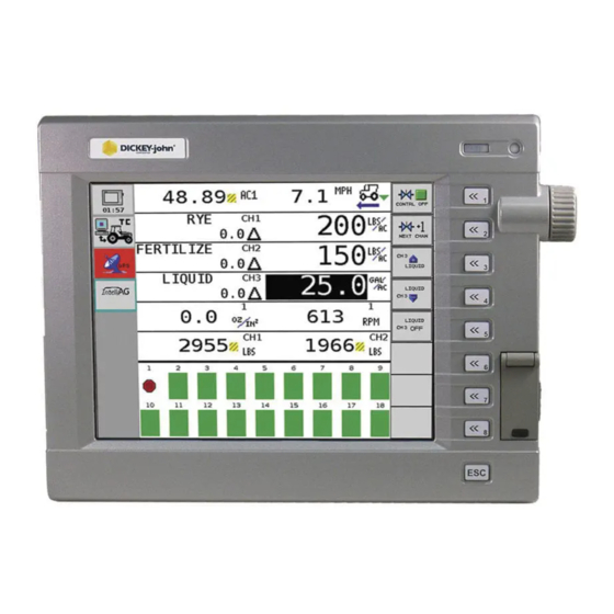
NOTE: Examples shown throughout this manual depict display screens of the 10” Virtual A 5” or 10” Virtual Terminal provides user interface with the IntelliAg system Terminal display. used for output and input of data. Reference the VT operator’s manual for setup and configuration instructions. -
Page 12: Master Switch
16 seed sensors. The WSMT module uses a 48-pin connector with a jackscrew to secure the connector to the module. The WSMT is typically mounted on the implement. 4 / SYSTEM OVERVIEW IntelliAg PDC User 2 & 3 11001-1509A-201105... -
Page 13: Working Set Member (Wsmb) Module (Optional)
One terminator is located on the cab harness, approximately 30 inches from the Virtual Terminal connector. • One terminator plugs into the implement harness of the last module connected to the CAN bus. Figure 5 Can Terminator SYSTEM OVERVIEW / 5 IntelliAg PDC User 2 & 3 11001-1509A-201105... - Page 14 OPERATOR’S MANUAL 6 / SYSTEM OVERVIEW IntelliAg PDC User 2 & 3 11001-1509A-201105...
-
Page 15: System Requirements
OPERATOR’S MANUAL SYSTEM REQUIREMENTS The minimum requirements to operate the IntelliAg Planter/Drill Control system consist of: • Virtual Terminal • Master Switch • Working Set Master • Two CAN terminators • TECU (10” VT only) Optional and not required for system operation: •... -
Page 16: Compatibility
– distance accumulator – control channel material accumulation 1-4 – channel product level 1-4 – hopper level status scan – boom status – guidance status COMPATIBILITY • Compatible with DICKEY-john sensors 8 / SYSTEM REQUIREMENTS IntelliAg PDC User 2 & 3 11001-1509A-201105... -
Page 17: Installation
1. Install the master switch within easy reach of the operator. 2. Once mounted, connect the master switch to the tractor (cab) harness as illustrated in (Figure 13) or (Figure 14). Figure 7 Master Switch INSTALLATION / 9 IntelliAg PDC User 2 & 3 11001-1509A-201105... -
Page 18: Working Set Master (Wsmt) Module
Ensure that module connectors do not face upward when implement is in a folded position as well. 2. Mount with the label side of module facing out. Do not mount with the connector facing up (see Caution). 10 / INSTALLATION IntelliAg PDC User 2 & 3 11001-1509A-201105... - Page 19 WSMT harness. A wide variety of harnesses are available to accommodate various numbers of sensor inputs. Install all seed sensors per the instructions included with the individual sensors. Secure any unused or excess cable lengths as necessary. INSTALLATION / 11 IntelliAg PDC User 2 & 3 11001-1509A-201105...
-
Page 20: Working Set Member (Wsmb) Module
Use the enclosure as a template to mark the location of the mounting holes. • Drill two 9/32 inch diameter holes where marked. • Attach to frame using 1/4 x 20 bolts or other fastening devices as illustrated in (Figure 11). 12 / INSTALLATION IntelliAg PDC User 2 & 3 11001-1509A-201105... - Page 21 1/4 x 20 BOLT 1/4 NUT 1/4 SPLIT LOCKWASHER IMPLEMENT FRAME OR SUPPORT 1/4 x 20 THREADED "U" BOLT OR 1/4 FLAT WASHER OTHER FASTENING DEVICE 1/4 NUT 1/4 SPLIT LOCKWASHER INSTALLATION / 13 IntelliAg PDC User 2 & 3 11001-1509A-201105...
- Page 22 11. Coil and secure any unused sensor connections. 12. The WSMB Module harness can accept a standard DICKEY-john PM style planter harness (single round 37-pin connector) or an SE style planter harness (1 gray 12-pin, 1 black 12-pin rectangular connector) depending on the WSMB harness used.
-
Page 23: Cab Harness Connections
Harness 467980126 467980452 Virtual Terminal 467980501 Ignition To Implement CAN Connect to switched Master Harness +12VDC Switch NOTE: This wire 467980124S1 must be connected to switched +12VDC Radar Speed Sensor INSTALLATION / 15 IntelliAg PDC User 2 & 3 11001-1509A-201105... - Page 24 If the Speed Sensor is to be connected to the WSMT, do not connect anything to the Speed Sensor connector on the Cab Harness. 16 / INSTALLATION IntelliAg PDC User 2 & 3 11001-1509A-201105...
- Page 25 467985060S1 Ignition Connect to switched To Implement CAN +12VDC Harness Master NOTE: This wire Switch must be connected to 467980124S1 switched +12VDC Radar Speed Sensor (If not connected to WSMT) INSTALLATION / 17 IntelliAg PDC User 2 & 3 11001-1509A-201105...
- Page 26 ECU to their respective connectors on the cab harness. If the speed sensor is to be connected to the WSMT, do not connect anything to the speed sensor connector on the cab harness. 18 / INSTALLATION IntelliAg PDC User 2 & 3 11001-1509A-201105...
- Page 27 Sensor is used, connect Switch 4 the IMP LIFT leads Radar Speed Sensor together 464820510 Labeled GND Speed Fan/Shaft RPM Sensor Planter Labeled RPM1 or Output Air Pressure Module Sensor 46682-0920S1 46798200051 INSTALLATION / 19 IntelliAg PDC User 2 & 3 11001-1509A-201105...
- Page 28 Seed Monitor Terminator Connect to next module harness or implement extension harness (Connect CAN terminator Standard Dj PM Style if this is the last module Planter Harness on the CAN bus) 20 / INSTALLATION IntelliAg PDC User 2 & 3 11001-1509A-201105...
-
Page 29: Sensor Installation
SEED SENSORS The system is compatible with all existing DICKEY-john seed sensors. Seed sensors may be connected to the WSMT module and all WSMB planter monitor modules. Any number of sensors up to the maximum capacity of the module may be connected. - Page 30 Incorrect Seed Sensor Module Connection INCORRECT Module Seed Sensor Harness Failure to correctly install seed sensors will result in incorrect row assignment on the planter monitor display functions and alarms. 22 / INSTALLATION IntelliAg PDC User 2 & 3 11001-1509A-201105...
-
Page 31: Hopper Level Sensors
The sensor is connected to the actuator harness. The Fan/RPM sensor connection is labeled RPM 1. AIR PRESSURE SENSORS The system is compatible with DICKEY-john air pressure sensors. One air pressure sensor with adapter harness connects to the RPM harness connection labeled RPM1. - Page 32 OPERATOR’S MANUAL 24 / INSTALLATION IntelliAg PDC User 2 & 3 11001-1509A-201105...
-
Page 33: System Modes
When the Master Switch is in the ON position, the Virtual Terminal (VT) is in Operate mode. In this mode, all enabled system components and control channels are operational, as well as all monitoring functions and system accumulators. Figure 19 Operate Mode SYSTEM MODES / 25 IntelliAg PDC User 2 & 3 11001-1509A-201105... -
Page 34: Available Buttons In Operate Mode
This button is only available for channels that are active and have had the target rate adjusted using the Increment or Decrement buttons in inc/dec % mode. The active channel displays in the button text. 26 / SYSTEM MODES IntelliAg PDC User 2 & 3 11001-1509A-201105... - Page 35 Specific setup screens can be accessed by pressing inside the yellow boxes for Channel, Material, Row, Module, Speed Set, and Accessory Sensor screens. SYSTEM MODES / 27 IntelliAg PDC User 2 & 3 11001-1509A-201105...
-
Page 36: Setup/Configuration Mode
CONTROL SETUP The Control Setup button accesses the Control Setup screen. Up to 16 different materials can be configured and stored for planter, liquid, fertilizer, RPM control, and monitor only. 28 / SYSTEM MODES IntelliAg PDC User 2 & 3 11001-1509A-201105... -
Page 37: Speed Set
CONFIGURATION The Configuration button accesses the Import/Export Configuration screen. System configurations can be exported to an SD card and imported to other Working Set Masters eliminating manual data entry. SYSTEM MODES / 29 IntelliAg PDC User 2 & 3 11001-1509A-201105... - Page 38 OPERATOR’S MANUAL 30 / SYSTEM MODES IntelliAg PDC User 2 & 3 11001-1509A-201105...
-
Page 39: User Levels
Level 2 mode. To change to User Level 1 Mode (Basic Operator View): 1. On the IntelliAg Main Work screen, press the Diagnostics button. 2. At the Diagnostics screen, press the Information button. 3. At the Information screen, press the Password button. -
Page 40: Change Operator Level To Oem/Dealer Level
LEVEL To change from operator level to OEM/dealer level, a 6-digit password is required. Password includes the five-digit serial number found on the label of the Working Set Master or on the IntelliAg Information screen. Figure 23 WSMT Serial Number 7.0”... - Page 41 6. Press the OK button. “Dealer screens on” appears at the bottom of screen confirming the password and that dealer screens are activated. 7. Press the Work Screen button to return to the Main Work screen. USER LEVELS / 33 IntelliAg PDC User 2 & 3 11001-1509-200903...
- Page 42 OPERATOR’S MANUAL 34 / USER LEVELS IntelliAg PDC User 2 & 3 11001-1509-200903...
-
Page 43: System Configuration
For operator convenience, it is recommended that materials and channels be established in the following order (refer to Figure 26): SYSTEM CONFIGURATION / 35 IntelliAg PDC User 2 & 3 11001-1509A-201105... - Page 44 Selecting an unassigned material button allows a new material to be created and assigned to a channel. Figure 26 Recommended Steps for Material/Channel Setup Step 1: Material Setup Step 2: Channel Setup Step 3: Material Library Screen 36 / SYSTEM CONFIGURATION IntelliAg PDC User 2 & 3 11001-1509A-201105...
-
Page 45: Control Channel And Material Selection
Setup screen changes to the name created at the Material Setup screen. The Material Setup screen can be accessed at any time by pressing the Material Name button. Refer to the Material Setup section for further instructions. SYSTEM CONFIGURATION / 37 IntelliAg PDC User 2 & 3 11001-1509A-201105... -
Page 46: Material Setup
Available characters are a combination of upper case, numbers, letters, symbols, and spaces. Figure 28 Edit Material Name at Material Setup Screen Material Name input box MATRL 2 Create Material Name 38 / SYSTEM CONFIGURATION IntelliAg PDC User 2 & 3 11001-1509A-201105... -
Page 47: Type
The Preset Method table allows user-defined target rates to be entered. When enabled, target rates can be adjusted from the Main Work screen using the Increment and Decrement buttons. Up to 10 preset target rates can be configured. SYSTEM CONFIGURATION / 39 IntelliAg PDC User 2 & 3 11001-1509A-201105... -
Page 48: Preset Method Disabled
Inc/Dec % rate set at the Material Setup screen. Value to the left of the triangle is the difference off of target rate. 40 / SYSTEM CONFIGURATION IntelliAg PDC User 2 & 3 11001-1509A-201105... -
Page 49: Material Setup Constants - Planter Control
EXAMPLE: Maximum Rate is set for 101. Target Rate is set for 100. If the % increase is set at 2%, the maximum rate of 101 will not be met because the % increase of 2% would exceed the 101 maximum rate limit. SYSTEM CONFIGURATION / 41 IntelliAg PDC User 2 & 3 11001-1509A-201105... -
Page 50: Seeds Per Rev
High Alarm example: If the Target Rate is 100.0 and the High Alarm is 5.0%, multiply 100.0 x 1.05 (a 5% increase) = 105.0. The alarm will activate at this population. 42 / SYSTEM CONFIGURATION IntelliAg PDC User 2 & 3 11001-1509A-201105... -
Page 51: Row Width
Both values are adjustable, allowing for numerous combinations. The default value is 2/1, which indicates a row failure threshold of 2 seeds in 1 second. SYSTEM CONFIGURATION / 43 IntelliAg PDC User 2 & 3 11001-1509A-201105... -
Page 52: Material Setup Constants-Gran Seed And Gran Fertilizer Control
EXAMPLE: Maximum Rate is set for 101. Target Rate is set for 100. If the % increase is set at 2%, the maximum rate of 101 will not be met because the % increase of 2% would exceed the 101 maximum rate limit. 44 / SYSTEM CONFIGURATION IntelliAg PDC User 2 & 3 11001-1509A-201105... -
Page 53: Density
High shaft RPM is the highest shaft RPM that the control channel will operate. PROD LEVEL ALARM The product level alarm sets the weight (lbs/Kg) to alert of low seed levels. The entered value is an estimate in lbs. SYSTEM CONFIGURATION / 45 IntelliAg PDC User 2 & 3 11001-1509A-201105... -
Page 54: Seeds Per Pound
Setup screen or the Row I/O screen. The system will use the last entered constants from either screen. However, it is recommended that patterns are set for each material at the Material Setup screen. 46 / SYSTEM CONFIGURATION IntelliAg PDC User 2 & 3 11001-1509A-201105... -
Page 55: On/Off Pattern
Both values are adjustable, allowing for numerous combinations. The default value is 2/1, which indicates a row failure threshold of 2 seeds in 1 second. SYSTEM CONFIGURATION / 47 IntelliAg PDC User 2 & 3 11001-1509A-201105... -
Page 56: Material Setup Constants-Liquid Flow
EXAMPLE: Maximum Rate is set for 101. Target Rate is set for 100. If the % increase is set at 2%, the maximum rate of 101 will not be met because the % increase of 2% would exceed the 101 maximum rate limit. 48 / SYSTEM CONFIGURATION IntelliAg PDC User 2 & 3 11001-1509A-201105... -
Page 57: Low Flow Limit
PRODUCT LEVEL ALARM The Product Level alarm sets the gallons left in the tank to trigger an alarm alerting of low liquid levels. The entered value is an estimate in gallons. SYSTEM CONFIGURATION / 49 IntelliAg PDC User 2 & 3 11001-1509A-201105... -
Page 58: Material Setup - Monitor Only
(centimeters) between rows with a resolution of 0.1. This value updates automatically with changes in the On/Off Pattern Setting option if the Auto Update Width option is set to Enabled. 50 / SYSTEM CONFIGURATION IntelliAg PDC User 2 & 3 11001-1509A-201105... -
Page 59: On/Off Pattern
Both values are adjustable, allowing for numerous combinations. The default value is 2/1, which indicates a row failure threshold of 2 seeds in 1 second. SYSTEM CONFIGURATION / 51 IntelliAg PDC User 2 & 3 11001-1509A-201105... -
Page 60: Material Setup Constants - Rpm Control
EXAMPLE: Maximum Rate is set for 101. Target Rate is set for 100. If the % increase is set at 2%, the maximum rate of 101 will not be met because the % increase of 2% would exceed the 101 maximum rate limit. 52 / SYSTEM CONFIGURATION IntelliAg PDC User 2 & 3 11001-1509A-201105... -
Page 61: Control Channel Setup
To configure more than one control channel, press the Next Channel button. IMPORTANT: It is recommended that Materials are created before configuring channels on the Channel Setup screen. CONTROL CHANNEL SETUP / 53 IntelliAg PDC User 2 & 3 11001-1509A-201105... -
Page 62: Planter Control Setup
Using the Increment/ Decrement buttons at the Main Work screen will set the flow rate for the control channel. No application rate feedback will display. 54 / CONTROL CHANNEL SETUP IntelliAg PDC User 2 & 3 11001-1509A-201105... -
Page 63: Drive Type
Sensor Constant establishes the number of pulses for one revolution of the must be determined for sensors application rate sensor. If a standard DICKEY-john application rate sensor is other than DICKEY-john. used, the value should be set to 360.0. - Page 64 • The system will delay the channel shutdown if the master switch is turned OFF and the implement is in the down position. 56 / CONTROL CHANNEL SETUP IntelliAg PDC User 2 & 3 11001-1509A-201105...
-
Page 65: Flush Enable
Flush Ground Speed feature displays on the Ground Speed Setup screen. 2. A Flush Ground Speed greater than 0 must be entered on the Ground Speed setup screen for this feature to operate. CONTROL CHANNEL SETUP / 57 IntelliAg PDC User 2 & 3 11001-1509A-201105... -
Page 66: Valve Calibration - Planter Control
1. Move the implement to the “raised” position. 2. Apply the tractor brakes and lock in the applied position. 3. Put the transmission in “park” or in a locked, neutral position. 58 / CONTROL CHANNEL SETUP IntelliAg PDC User 2 & 3 11001-1509A-201105... -
Page 67: Fill Disk
7. Press the Start button. The seed meters will turn for 1 revolution, then stop. 8. Pressing the Stop button will also terminate the test. STOP CONTROL CHANNEL SETUP / 59 IntelliAg PDC User 2 & 3 11001-1509A-201105... - Page 68 OPERATOR’S MANUAL Figure 41 Fill Disk Screen for One Control Channel 60 / CONTROL CHANNEL SETUP IntelliAg PDC User 2 & 3 11001-1509A-201105...
-
Page 69: Continuous Test
Continuous Test to see row-to-row variability. TEST TARGET POP Test Target Pop is the seed rate at which the test is performed. This value is the current target rate and is automatically populated. CONTROL CHANNEL SETUP / 61 IntelliAg PDC User 2 & 3 11001-1509A-201105... -
Page 70: Test Seed Count
4. The following parameters must be entered to perform a 5 Rev Test. – Test Ground Speed – Row The values entered do not affect any other setup values that have previously been tested. Figure 43 5 Rev Test Screen 62 / CONTROL CHANNEL SETUP IntelliAg PDC User 2 & 3 11001-1509A-201105... -
Page 71: Test Ground Speed
REMOTE TEST SWITCH STOP A momentary switch can be purchased from DICKEY-john that allows the the control to be turned on/off during the Continuous and 5 Rev tests. The switch allows the operator to go back to the implement to perform the test and investigate mechanical issues or perform seed counts instead of performing the test inside the cab from the Virtual Terminal. -
Page 72: Granular Seed And Granular Fert Setup
A valve, usually hydraulic, which varies the oil flow to a hydraulic motor proportioned to electric current supplied. This type of valve consists of a flow cartridge and coil assembly. 64 / CONTROL CHANNEL SETUP IntelliAg PDC User 2 & 3 11001-1509A-201105... - Page 73 Sensor Constant establishes the number of pulses for one revolution of the must be determined for sensors metering unit. If a standard DICKEY-john application rate sensor is used, other than DICKEY-john. the value should be set to 360.0.
- Page 74 The control channel delays after the master switch has been turned A delay also occurs and then shutdowns the control channel when the • master switch is turned OFF. 66 / CONTROL CHANNEL SETUP IntelliAg PDC User 2 & 3 11001-1509A-201105...
-
Page 75: Valve Calibration - Gran Seed And Gran Fert
The Channel On button appears on this screen only if the channel is turned off. The channel must be ON before performing a valve calibration. Press the Channel On button to turn the channel on. CONTROL CHANNEL SETUP / 67 IntelliAg PDC User 2 & 3 11001-1509A-201105... -
Page 76: Fill Disk
5. With brakes locked and transmission in the park position, start the engine. 6. Engage hydraulics and run engine at normal speed until hydraulic fluid is at operating temperature. 68 / CONTROL CHANNEL SETUP IntelliAg PDC User 2 & 3 11001-1509A-201105... - Page 77 7. Press the Start button. The seed meters will turn for one revolution, then stop. STOP 8. Press the Stop button to terminate test. Figure 46 Fill Disk for a Granular Seeding Channel CONTROL CHANNEL SETUP / 69 IntelliAg PDC User 2 & 3 11001-1509A-201105...
-
Page 78: Limit Output
8. Press the Start button and the valve calibration will immediately begin. The calibration will run using the new max flow value. 70 / CONTROL CHANNEL SETUP IntelliAg PDC User 2 & 3 11001-1509A-201105... -
Page 79: Spreader Calibration- Gran Seed And Gran Fertilizer
(Lbs/ft , Lbs/bu). If not known, enter a value of 1 Lbs/ft SPREADER CONSTANT Determines how many pulses the application rate sensor produces per volume of material discharged. CONTROL CHANNEL SETUP / 71 IntelliAg PDC User 2 & 3 11001-1509A-201105... -
Page 80: Target Meter Rpm
SHAFT TURN The Shaft Turn button turns the shaft one (1) gear revolution and fills the seed meter for instant seed flow when the control is turned on. 72 / CONTROL CHANNEL SETUP IntelliAg PDC User 2 & 3 11001-1509A-201105... -
Page 81: Liquid Flow Setup
Three drive type selections are available based on the following: SERVO A ball valve or butterfly valve that is driven by an electric motor gearbox and the valve is installed in the main product delivery line. CONTROL CHANNEL SETUP / 73 IntelliAg PDC User 2 & 3 11001-1509A-201105... - Page 82 Ground Speed Setup section for Precharge Ground Speed setup information). IMPORTANT: A Precharge number MUST be entered as a positive number (5.0 seconds) for the system to identify between a Precharge or Delay Time state. 74 / CONTROL CHANNEL SETUP IntelliAg PDC User 2 & 3 11001-1509A-201105...
- Page 83 Flush Ground Speed feature displays on the Ground Speed Setup screen. 2. A Flush Ground Speed greater than 0 must be entered on the Ground Speed setup screen for this feature to operate. CONTROL CHANNEL SETUP / 75 IntelliAg PDC User 2 & 3 11001-1509A-201105...
-
Page 84: Valve Calibration - Liquid
4. Start the tractor and engage the hydraulic system. 5. Run the engine at normal operating speed until the hydraulic fluid is at normal operating temperature. 6. Press the Start button. 76 / CONTROL CHANNEL SETUP IntelliAg PDC User 2 & 3 11001-1509A-201105... - Page 85 8. Press the Start button and the valve calibration will immediately begin. The calibration will run using the new max flow value. CONTROL CHANNEL SETUP / 77 IntelliAg PDC User 2 & 3 11001-1509A-201105...
-
Page 86: Liquid Flow Calibration
3. Press the Start button to initiate flow calibration procedure. 4. Press Stop when container is full. 5. Enter amount (gallons) dispensed in the Total Amount Collect field. 6. Press Save button to accept the selection. STOP 78 / CONTROL CHANNEL SETUP IntelliAg PDC User 2 & 3 11001-1509A-201105... - Page 87 Tanks must contain material. Be prepared to catch the material in a container so it can be weighed at the end of the calibration. CONTROL CHANNEL SETUP / 79 IntelliAg PDC User 2 & 3 11001-1509A-201105...
-
Page 88: Rpm Control Setup
Using the Increment/ Decrement buttons from the Main Work screen will set the RPM for the control channel. No application rate feedback will display. 80 / CONTROL CHANNEL SETUP IntelliAg PDC User 2 & 3 11001-1509A-201105... -
Page 89: Drive Type
SENSOR CONSTANT Sensor Constant establishes the number of pulses for one revolution of the metering unit. If a standard DICKEY-john application rate sensor is used, the value should be set to 360.0. MASTER SWITCH OFF Disabled-Shuts down the control channel when booms are turned off. -
Page 90: Disable Control On Control Failure Alarm
ENABLED setting shuts down the control channels when the RPM sensor fails • DISABLED setting disables the function. All non-RPM control channels continue to operate with a failed RPM sensor. 82 / CONTROL CHANNEL SETUP IntelliAg PDC User 2 & 3 11001-1509A-201105... -
Page 91: Valve Calibration - Rpm Control
3. Put the transmission in “park” or in a locked, neutral position. 4. Start the tractor and engage the hydraulic system. 5. Run the engine at normal operating speed until the hydraulic fluid is at normal operating temperature. CONTROL CHANNEL SETUP / 83 IntelliAg PDC User 2 & 3 11001-1509A-201105... - Page 92 8. Press the Start button and the valve calibration will immediately begin. The calibration will run using the new max flow value. 84 / CONTROL CHANNEL SETUP IntelliAg PDC User 2 & 3 11001-1509A-201105...
-
Page 93: Module Configuration
OPERATOR’S MANUAL MODULE CONFIGURATION System components must be installed correctly and vehicle parameters entered into the IntelliAg system for effective operation. The following steps provide guidelines for entering those parameters. IMPORTANT: Place the master switch in the OFF position to access and input data into the SETUP/CONFIGURATION mode. -
Page 94: Module Address
Row 1. Module Address 2 should be assigned to the module connected to the next set of rows. The assigned numbering continues until all rows have been numbered. 86 / CONTROL CHANNEL SETUP IntelliAg PDC User 2 & 3 11001-1509A-201105... -
Page 95: Auto Sort
1. Press the Module Configuration button to access the Module Configuration screen. 2. Press the Auto Config button. An hour glass appears in the upper right corner while the system is configuring. CONTROL CHANNEL SETUP / 87 IntelliAg PDC User 2 & 3 11001-1509A-201105... -
Page 96: Auto Sort And Auto Config Examples
10036 5001 WSMB - 18R Move WSMT after Auto Sort 10036 WSMB - 18R 10245 WSMT - PDC 10037 WSMB - 18R 10038 WSMB - 18R 5000 5001 88 / CONTROL CHANNEL SETUP IntelliAg PDC User 2 & 3 11001-1509A-201105... - Page 97 Module Address 1. No Working Set Member is utilized. Figure 58 16 Row Installation Example (WSMT only) Module Configuration Screen Seed Sensor Configuration Screen Working Set Master 10014 CONTROL CHANNEL SETUP / 89 IntelliAg PDC User 2 & 3 11001-1509A-201105...
- Page 98 Member is utilized to monitor rows 13-24. Figure 59 24 Row Installation Example Seed Sensor Configuration Screen Module Configuration Screen 1-12 13-24 Working Set Master 10014 Working Set Member 10259 90 / CONTROL CHANNEL SETUP IntelliAg PDC User 2 & 3 11001-1509A-201105...
- Page 99 Working Set Member Module Address 1 Rows 1-12 10014 FRONT Working Set Member Working Set Member Module Address 4 Module Address 3 Rows 37-48 Rows 25-36 10426 10344 BACK CONTROL CHANNEL SETUP / 91 IntelliAg PDC User 2 & 3 11001-1509A-201105...
-
Page 100: Row Assignment
Assignment screen. 2. Press the Sensor Detect button to detect and test seed sensors. An hour glass will appear in the upper right corner while the sensors are tested. 92 / CONTROL CHANNEL SETUP IntelliAg PDC User 2 & 3 11001-1509A-201105... -
Page 101: Row Status/Row Width Setup
Auto Update Width option is set to Enabled. AUTO UPDATE WIDTH Auto Update Width automatically updates the Row Width and Implement Width settings when changes are made to the Pattern Setting option. CONTROL CHANNEL SETUP / 93 IntelliAg PDC User 2 & 3 11001-1509A-201105... -
Page 102: Implement Width
Individual rows in the Row Setup screen can still be manually edited to Population, Blockage, or Off before or after a pattern is selected. The pattern setting, when selected, will override previous individual existing row settings. 94 / CONTROL CHANNEL SETUP IntelliAg PDC User 2 & 3 11001-1509A-201105... -
Page 103: Blockage Pattern
Even rows use Recon and odd rows use Hi Rate • Every 2nd Row Pop (B_B_B_) Pattern Definitions Even rows use Hi Rate and odd rows use Recon Blockage Population = - CONTROL CHANNEL SETUP / 95 IntelliAg PDC User 2 & 3 11001-1509A-201105... -
Page 104: Hopper Assignment
The HOPP #’s value is automatically configured Hopper Assignment screen. for proper numbering sequence for each module based upon the module address value when an Auto Config is performed. 96 / CONTROL CHANNEL SETUP IntelliAg PDC User 2 & 3 11001-1509A-201105... -
Page 105: Hopper Set
Sets the active state to “High” signifying that an alarm is generated if ACTIVE LO. the sensor’s output is in a high state. Use this setting if the connected sensor outputs a high condition when active. CONTROL CHANNEL SETUP / 97 IntelliAg PDC User 2 & 3 11001-1509A-201105... -
Page 106: Alarm Delay
Accessory Assignment Screen IMPORTANT: Auto Config detects the presence of a pressure sensor and automatically configures and populates into the Accessory Assignment screen. An RPM sensor must be configured manually. 98 / CONTROL CHANNEL SETUP IntelliAg PDC User 2 & 3 11001-1509A-201105... -
Page 107: Of Pressure/Rpm Sensors
The value is entered in RPM. Assignment screen. LOW ALARM The Low Alarm option sets the RPM value at which a low RPM warning error is generated. The value is entered in RPM. CONTROL CHANNEL SETUP / 99 IntelliAg PDC User 2 & 3 11001-1509A-201105... -
Page 108: High Alarm Delay
DISABLED will disable the function. The control channels continue to operate normally regardless of the RPM value. However, when the low RPM state occurs, the information alarm still occurs. 100 / CONTROL CHANNEL SETUP IntelliAg PDC User 2 & 3 11001-1509A-201105... -
Page 109: Pressure Sensor Setup
LOW ALARM DELAY The Low Alarm Delay establishes the delay between the detection of a low pressure alarm condition and the resulting alarm display. The value is entered in seconds. CONTROL CHANNEL SETUP / 101 IntelliAg PDC User 2 & 3 11001-1509A-201105... -
Page 110: Pressure Filter
0%. If the pressure readout on the Main Operate screen is oscillating in excess of 10%, increasing the filter value filters the signal to reduce the oscillation. For a true pressure value this number should be set to 0%. 102 / CONTROL CHANNEL SETUP IntelliAg PDC User 2 & 3 11001-1509A-201105... -
Page 111: Row Monitor Setup
If the value is set to 10, a row must be in a High intervals does not provide any Population Alarm condition continuously for 10 seconds before the alarm delay at all. will be issued. CONTROL CHANNEL SETUP / 103 IntelliAg PDC User 2 & 3 11001-1509A-201105... -
Page 112: Low Alarm Delay
Both values are adjustable, allowing for numerous combinations. The default value is 2/1, which indicates a row failure threshold of 2 seeds in 1 second. 104 / CONTROL CHANNEL SETUP IntelliAg PDC User 2 & 3 11001-1509A-201105... -
Page 113: Ground Speed Setup
ON at the speed that has been programmed. This value can be set to any speed within the delivery capabilities of the system. CONTROL CHANNEL SETUP / 105 IntelliAg PDC User 2 & 3 11001-1509A-201105... -
Page 114: Gspd Constant
The control will operate at this speed until actual ground speed rises above the minimum override speed or the actual speed drops below the shutoff speed. 106 / CONTROL CHANNEL SETUP IntelliAg PDC User 2 & 3 11001-1509A-201105... -
Page 115: Master Switch Timeout
An Alarm Cancel button allows the alarm to be deactivated during the current power cycle. If an implement lift switch is not required, this function should be disabled. CONTROL CHANNEL SETUP / 107 IntelliAg PDC User 2 & 3 11001-1509A-201105... -
Page 116: Ground Speed Calibration
4. To ensure accuracy, record the number and repeat this process two additional times. Average the three numbers recorded. 5. Enter the average calibration number. 6. Save the desired settings. 108 / CONTROL CHANNEL SETUP IntelliAg PDC User 2 & 3 11001-1509A-201105... -
Page 117: 10" Vt Aux Input/Function Assignment
OPERATOR’S MANUAL 10” VT AUX INPUT/FUNCTION ASSIGNMENT The Auxiliary Input/Function Assignment screen configures the system’s master switch input to the TECU so that it will work with the IntelliAg control function. IMPORTANT: On initial powerup, a Master Switch Assignment alarm activates requiring a switch assignment. -
Page 118: 5" Vt Aux Input/Function Assignment
1. Press the ESC key 2 times to activate the Virtual Terminal Setup screen. 2. Press the Auxiliary Input/Function Setup button to access the Auxiliary Input/ Function Setup screen (Figure 76). 110 / CONTROL CHANNEL SETUP IntelliAg PDC User 2 & 3 11001-1509A-201105... - Page 119 Aux Input Configuration Screen Down Default The Master Switch Connection icon may appear automatically on Clear this screen, or may appear after the DEFAULT softkey has been pressed. Cancel CONTROL CHANNEL SETUP / 111 IntelliAg PDC User 2 & 3 11001-1509A-201105...
- Page 120 Master Switch Button Activation alarm must be acknowledged before equipment operates (refer to Figure 30). This alarm occurs the first time the Master Switch button is pressed after every power up. 112 / CONTROL CHANNEL SETUP IntelliAg PDC User 2 & 3 11001-1509A-201105...
-
Page 121: Work Screen Configuration
Bar graph setup allows customization of the rows being monitored and displayed on the Main Work screen. A maximum of 2 lines and 24 columns can display. Default displays 1 line and 24 columns. CONTROL CHANNEL SETUP / 113 IntelliAg PDC User 2 & 3 11001-1509A-201105... -
Page 122: Return System Active Delay
RETURN SYSTEM ACTIVE DELAY Setting a time delay (seconds) in the Return System Active Delay input box will trigger the IntelliAg Main Work screen to automatically return as the active screen view when other system application screens are used, i.e., Task Controller or Autopilot. -
Page 123: Summary Screen
Speed Set • Hopper, Pressure, RPM Setup 1. At the Main Work screen, press the Summary button to access the Summary screen. Figure 80 Summary Screen Control Channel Selection CONTROL CHANNEL SETUP / 115 IntelliAg PDC User 2 & 3 11001-1509A-201105... - Page 124 OPERATOR’S MANUAL 116 / CONTROL CHANNEL SETUP IntelliAg PDC User 2 & 3 11001-1509A-201105...
-
Page 125: Data Items
OPERATOR’S MANUAL DATA ITEMS Data items are selected at Screen Configuration. The following illustrates NOTE: Data Items on the Main Work screen with a check box allows available display parameters and their respective functions. Display the number to be reset to zero. parameter placement can be moved to display on the Main Work screen to individual preferences. -
Page 126: Control Rate Channels 1-4
The value to the right is the population data. Dwell time for each display is four seconds. This Data Item displays on an entire row of the Work screen. 118 / DATA ITEMS IntelliAg PDC User 2 & 3 11001-1509A-201105... -
Page 127: Pop Min Row
The value on the right is the spacing. Dwell time for each display is four seconds. This Data Item displays on an entire row of the Work screen. DATA ITEMS / 119 IntelliAg PDC User 2 & 3 11001-1509A-201105... -
Page 128: Spacing Min Row
The value on the right is the seeds per distance data. Dwell time for each display is four seconds. This Data Item displays on an entire row of the Work screen. 120 / DATA ITEMS IntelliAg PDC User 2 & 3 11001-1509A-201105... -
Page 129: Seed/Distance Min Row
Singulation Min Max Scan alternates the display of the minimum row singulation and maximum row singulation every two seconds. When a minimum row displays, the corresponding symbol is shown with the row number. DATA ITEMS / 121 IntelliAg PDC User 2 & 3 11001-1509A-201105... -
Page 130: Ground Speed
2 Area is calculated in the same manner as Total Area. This accumulator is independent of any other area accumulator and can be reset to 0.0 at any time. Current area is retained after power down. 122 / DATA ITEMS IntelliAg PDC User 2 & 3 11001-1509A-201105... -
Page 131: Channels 1 - 4 Area
0 . 0 0 System Active Time records the amount of time the master switch is in the ON position indicating the actual number of hours equipment has been operating. DATA ITEMS / 123 IntelliAg PDC User 2 & 3 11001-1509A-201105... -
Page 132: Seed Count Accum Row
Pressure Scan scans through all active pressure sensors sequentially, displaying the actual pressure measured in oz/in (kPa) in four-second intervals. The current sensor is identified by the number above the pressure symbol. 124 / DATA ITEMS IntelliAg PDC User 2 & 3 11001-1509A-201105... -
Page 133: Rpm Scan
Boom Status indicates the status of each boom section. The Boom Status feature is only operational with Liquid Control channels when a DICKEY-john boom switch module and boom output module are installed for boom control. This Data Item will scan through 12 sections at a time on an entire row. - Page 134 OPERATOR’S MANUAL 126 / DATA ITEMS IntelliAg PDC User 2 & 3 11001-1509A-201105...
-
Page 135: Pre-Operating Preparation
5. Press the Start button. The seed meters will turn for 1 revolution, then stop. 6. Pressing the Stop button will also terminate the test. Figure 81 STOP Fill Disk Screen for All Planter Controls PRE-OPERATING PREPARATION / 127 IntelliAg PDC User 2 & 3 11001-1509A-201105... - Page 136 OPERATOR’S MANUAL 128 / PRE-OPERATING PREPARATION IntelliAg PDC User 2 & 3 11001-1509A-201105...
-
Page 137: System Operation
2. Operation will immediately stop when the ground speed is 0 or the implement is raised to disengage. Figure 82 Main Work Screen Functions Target Rate Inc/Dec % Target Rate Preset Enabled Implement Lift Up/Down Indicator Accumulator Reset Indicators SYSTEM OPERATION / 129 IntelliAg PDC User 2 & 3 11001-1509A-201105... -
Page 138: Operate Screen Symbols
Row Indicators in the bar graph area on the bottom of the Work screen indicate seed rate for each row. The size of the bar graphic is set on the Work Configuration screen by pressing the Work Screen button. 130 / SYSTEM OPERATION IntelliAg PDC User 2 & 3 11001-1509A-201105... -
Page 139: Autopilot Steering Navigation
Singulation refers to the portion of seeds planted individually, rather than in groups. MATERIAL NAME Active Material Name for a control channel created at the Control Channel MATRL 1 screen. SYSTEM OPERATION / 131 IntelliAg PDC User 2 & 3 11001-1509A-201105... -
Page 140: Population Max Row
Reference the System Configuration section for control channel and ground NOTE: Master switch must be turned ON to activate a precharge speed setup instructions. state. 132 / SYSTEM OPERATION IntelliAg PDC User 2 & 3 11001-1509A-201105... - Page 141 The rate instrument will populate with the word “CHARGE” and the countdown timer. The timer gives the user the ability to see how much precharge time is left before precharge will abort. SYSTEM OPERATION / 133 IntelliAg PDC User 2 & 3 11001-1509A-201105...
-
Page 142: Flush Enable
2. Press and hold the Flush Enable button to dispense material. 3. Release the Flush Enable button to stop dispensing material. Once speed is above shutoff speed, flush is aborted and ground speed based control will take over. 134 / SYSTEM OPERATION IntelliAg PDC User 2 & 3 11001-1509A-201105... -
Page 143: System Information And Diagnostics
Reset Time button. SYSTEM ACTIVE AREA System Active Area is the accumulated area covered while the Master Switch is on. System Active Area cannot be reset. SYSTEM OPERATION / 135 IntelliAg PDC User 2 & 3 11001-1509A-201105... -
Page 144: Distance
CH TARGET The Channel Target value is the current channel’s rate as entered into the Target Rate constant on the Channel Configuration screen. 136 / SYSTEM OPERATION IntelliAg PDC User 2 & 3 11001-1509A-201105... -
Page 145: Ch Actual Rate
The IO Hopper 1 value is the current state of the hopper sensor. If the sensor is not blocked, the value will be “1”. A blocked sensor’s value will be “1”. SYSTEM OPERATION / 137 IntelliAg PDC User 2 & 3 11001-1509A-201105... -
Page 146: Io Imp Lift
1. Press the Enable Manual Valve button to run the current selected channel. This allows for manual open and close of valve position. IMPORTANT: The Enable feature will only operate on the Diagnostics screen. 138 / SYSTEM OPERATION IntelliAg PDC User 2 & 3 11001-1509A-201105... -
Page 147: Seed Count Screen
4. To reset the seed count on all rows, press the Count Reset button. 5. Press the Work Screen button to exit or press the Accumulators button to return to the Accumulator screen. SYSTEM OPERATION / 139 IntelliAg PDC User 2 & 3 11001-1509A-201105... -
Page 148: Information Screen
Module position cannot be altered on this screen and can only be established on the Module Configuration screen. Press the Information button to access the Information screen. Figure 89 Information Screen Software Version 140 / SYSTEM OPERATION IntelliAg PDC User 2 & 3 11001-1509A-201105... -
Page 149: Resetting Novram Values
Some alarms (such as the Master Switch alarm) require a specific action by the operator before the alarm condition will cease. In these cases, instructions are indicated on the alarm display. SYSTEM OPERATION / 141 IntelliAg PDC User 2 & 3 11001-1509A-201105... -
Page 150: Alarm Log
– The down arrow in the lower left at screen bottom signifies that more alarms are present and accessible by pressing the Previous or Next buttons. Figure 91 Alarm Log Screen 142 / SYSTEM OPERATION IntelliAg PDC User 2 & 3 11001-1509A-201105... -
Page 151: Alarm Detail
To reset the Alarm Log, press the Alarm Reset button. 1. Press YES button to clear. 2. Press NO button to return to Alarm Log Detail screen. Figure 93 Reset Alarm Log Screen SYSTEM OPERATION / 143 IntelliAg PDC User 2 & 3 11001-1509A-201105... - Page 152 OPERATOR’S MANUAL 144 / SYSTEM OPERATION IntelliAg PDC User 2 & 3 11001-1509A-201105...
-
Page 153: Task Controller
From behind the implement facing tractor: – Channels to the left of the hitch/GPS receiver point (negative entry) (-y) – Channels to the right of the hitch/GPS receiver point (positive entry) (+y) TASK CONTROLLER / 145 IntelliAg PDC User 2 & 3 11001-1509A-201105... -
Page 154: Channel Linking
Channels on and off simultaneously. MATERIAL APPLICATION RATES The Material Rate button resets a system to IntelliAg rates that has been running a task under Task Controller map control. An SD Card graphic icon on the IntelliAg Work screen indicates this condition. The Material Rate button appears on the IntelliAg Work screen to select current rates or to reload IntelliAg rates. -
Page 155: Import/Export Data
If a Task Controller alarm occurs: – Press the TC Rate button to continue to run a task at the Task Controller rate – Press the Material Rate button to reset the system to IntelliAg rates Figure 96 Task Controller Alarm... - Page 156 1. Verify an SD card is inserted into the VT and all system electronics and members are connected properly and configured correctly. 2. From the IntelliAg Main Work screen, press the Next Page button to access the Config button. EXPORT DATA 1.
- Page 157 OPERATOR’S MANUAL Figure 98 Import Data Validation Screen TASK CONTROLLER / 149 IntelliAg PDC User 2 & 3 11001-1509A-201105...
- Page 158 OPERATOR’S MANUAL 150 / TASK CONTROLLER IntelliAg PDC User 2 & 3 11001-1509A-201105...
-
Page 159: Troubleshooting & Alarms
In these cases, the instructions to proceed are indicated in the alarm display. The following table describes the possible alarm conditions, causes, and remedies. TROUBLESHOOTING & ALARMS / 151 IntelliAg PDC User 2 & 3 11001-1509A-201105... - Page 160 OPERATOR’S MANUAL 152 / TROUBLESHOOTING & ALARMS IntelliAg PDC User 2 & 3 11001-1509A-201105...
- Page 161 Channel Configuration screen. Perform a valve calibration. 2. Incorrect feedback sensor installation. 2. Verify correct installation of the feedback sensor. 3. Defective feedback sensor. 3. Inspect feedback sensor for damage or replace. TROUBLESHOOTING & ALARMS / 153 IntelliAg PDC User 2 & 3 11001-1509A-201105...
- Page 162 2. Inspect seed sensor for damage. 2. Defective seed sensor. Replace if necessary. 3. Defective module. 3. Inspect module for damage. Replace if 4. Running out of seed. necessary. 4. Fill with seed. 154 / TROUBLESHOOTING & ALARMS IntelliAg PDC User 2 & 3 11001-1509A-201105...
- Page 163 2. Defective module or damaged module 2. Inspect module and/or module harness harness. for damage. Replace if necessary. 3. Additional seed sensor detected. 3. Verify correct # ROWS setting for each module. TROUBLESHOOTING & ALARMS / 155 IntelliAg PDC User 2 & 3 11001-1509A-201105...
- Page 164 1. Verify proper implement operation/setup. setup. 2. Defective RPM sensor. 2. Inspect RPM sensor for damage. Replace if necessary. 3. Defective module. 3. Inspect module for damage. Replace if necessary. 156 / TROUBLESHOOTING & ALARMS IntelliAg PDC User 2 & 3 11001-1509A-201105...
- Page 165 2. Damaged module harness. 2. Inspect module harness for damage. Repair or replace. 3. Defective module. 3. Inspect module for damage. Replace if necessary. 4. Low RPM 4. Increase RPM. TROUBLESHOOTING & ALARMS / 157 IntelliAg PDC User 2 & 3 11001-1509A-201105...
- Page 166 1. RPM Channels are off. System may not 1. Acknowledge alarm to leave RPM off Alarm operate properly. control channels off. 2. Press “CHAN ON” to turn all RPM channels on. 158 / TROUBLESHOOTING & ALARMS IntelliAg PDC User 2 & 3 11001-1509A-201105...
- Page 167 Task Controller Data 1. Task Controller is setting target rates 1. Restart Task Controller task. Logging Error without logging the data. 2. Cycle power to entire system. TROUBLESHOOTING & ALARMS / 159 IntelliAg PDC User 2 & 3 11001-1509A-201105...
- Page 168 OPERATOR’S MANUAL 160 / TROUBLESHOOTING & ALARMS IntelliAg PDC User 2 & 3 11001-1509A-201105...
-
Page 169: Appendix
RPM Configuration High Alarm Low Alarm High Alarm Delay Low Alarm Delay Constant Disable Control Low Alarm Pressure Configuration High Alarm Low Alarm High Alarm Delay Low Alarm Delay Pressure Filter APPENDIX / 161 IntelliAg PDC User 2 & 3 11001-1509A-201105... - Page 170 Row Fail Rate Ground Speed Configuration Source Manual Speed Ground Speed Constant Shutoff Speed Minimum Override Master Sw Timeout Grouind Speed Fail Alarm Delay Implement Lift Precharge Speed Flush Speed 162 / APPENDIX IntelliAg PDC User 2 & 3 11001-1509A-201105...
-
Page 171: Warranty
OPERATOR’S MANUAL SYSTEM CONFIGURATION WORKSHEET - WORK SCREEN Work Screen 1 Large Bargraphs Work Screen 2 Work Screen 3 APPENDIX / 163 IntelliAg PDC User 2 & 3 11001-1509A-201105... - Page 172 Target Rate Max Rate Min Rate Inc/Dec % Seeds Per Rev Density Spreader Constant Seeds per pound Low Limit High Limit Low Pop Alarm High Pop Alarm Product Level Alarm 164 / APPENDIX IntelliAg PDC User 2 & 3 11001-1509A-201105...
- Page 173 Rate 7 Rate 8 Rate 9 Rate 10 Seeds Per Rev Density Spreader Constant Seeds per pound Low Limit High Limit Low Pop Alarm High Pop Alarm Product Level Alarm APPENDIX / 165 IntelliAg PDC User 2 & 3 11001-1509A-201105...
- Page 174 OPERATOR’S MANUAL 166 / APPENDIX IntelliAg PDC User 2 & 3 11001-1509A-201105...
- Page 175 Europe: DICKEY-john Europe S.A.S, 165, boulevard de Valmy, 92706 – Colombes – France TEL: 33 (0) 1 41 19 21 80, FAX: 33 (0) 1 47 86 00 07 WEB: www.dickey-john.eu Copyright 2009 DICKEY-john Corporation Specifications subject to change without notice.
Need help?
Do you have a question about the IntelliAg and is the answer not in the manual?
Questions and answers