Table of Contents
Advertisement
Quick Links
TABLE OF CONTENTS
Introduction .......................................................................................................... 1
Features............................................................................................................................. 1
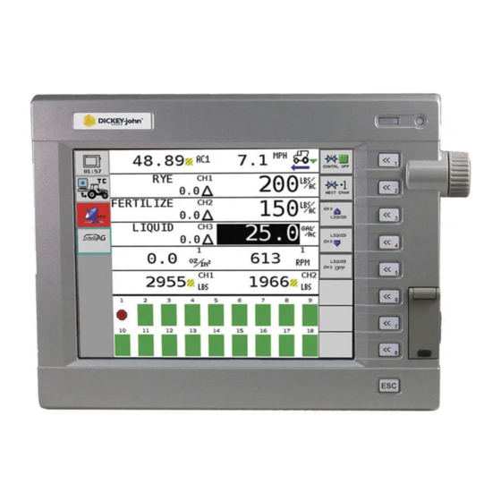
Main Work Screen ............................................................................................................. 1
Work Screen Symbols ....................................................................................................... 2
Target Rate ....................................................................................................................................... 2
Target Increase/Decrease % Rate.................................................................................................... 2
Target Preset Rate............................................................................................................................ 2
Implement Lift Switch ........................................................................................................................ 2
Task Controller.................................................................................................................................. 3
Row Indicators .................................................................................................................................. 3
Autopilot Steering Navigation............................................................................................................ 3
Accumulators .................................................................................................................................... 3
Population Row Scan........................................................................................................................ 3
Singulation Average Population ........................................................................................................ 4
Material Name................................................................................................................................... 4
Population Max Row ......................................................................................................................... 4
Population Min Row .......................................................................................................................... 4
Pre-Operating Preparation .................................................................................. 5
Pre-Defined Constants ...................................................................................................... 5
Fill Disk.............................................................................................................................................. 5
System Operation ................................................................................................ 7
Start ................................................................................................................................... 7
Stop ................................................................................................................................... 7
Operate Function Buttons .................................................................................................. 8
Master Switch On/Off ........................................................................................................................ 8
Next Channel .................................................................................................................................... 8
Increment .......................................................................................................................................... 8
Decrement......................................................................................................................................... 8
Inc/Dec Reset to Target .................................................................................................................... 8
Turn On/Off Channel......................................................................................................................... 8
Next Screen ...................................................................................................................................... 9
Non Operate Mode Buttons ............................................................................................... 9
Next Page ......................................................................................................................................... 9
Planter Fill Disk ................................................................................................................................. 9
Diagnostics........................................................................................................................................ 9
Alarm Log.......................................................................................................................................... 9
Summary........................................................................................................................................... 9
Additional Operating Functions........................................................................................ 10
Precharge Time............................................................................................................................... 10
Delay Time ...................................................................................................................................... 11
Flush Enable ................................................................................................................................... 11
IntelliAg PDC User Level 1
11001-1510-200904
i
Advertisement
Table of Contents

Related Manuals for Dickey-John IntelliAg


Summary of Contents for Dickey-John IntelliAg
-
Page 1: Table Of Contents
Non Operate Mode Buttons ....................9 Next Page ............................9 Planter Fill Disk ..........................9 Diagnostics............................9 Alarm Log............................9 Summary............................9 Additional Operating Functions..................10 Precharge Time..........................10 Delay Time ............................11 Flush Enable ........................... 11 IntelliAg PDC User Level 1 11001-1510-200904... - Page 2 Diagnostics Manual Valve Position ................. 15 Manual Open of Channel......................... 15 Information Screen ......................16 Acknowledging Alarm Conditions ..................17 Alarm Log ........................17 Alarm Detail ........................18 Troubleshooting & Alarms ................19 Warranty......................21 IntelliAg PDC User Level 1 11001-1510-200904...
-
Page 3: Introduction
The IntelliAg application controller is a precision farming system that provides communication between the implement and tractor. Because IntelliAg is designed to the ISO 11783 standard, it is interchangeable with other manufactuers’ compatible equipment. The DICKEY-john IntelliAg system can be used with: •... -
Page 4: Work Screen Symbols
The Implement Lift Switch box on the Implement Lift Ground Speed Configuration screen must be enabled if an implement Indicator lift switch is used. (Up Position-RED) Refer to the Implement Lift Sensor instructions for installation location. 2 / INTRODUCTION IntelliAg PDC User Level 1 11001-1510-200904... -
Page 5: Task Controller
The scans continue sequentially in four-second intervals unless the rotary knob is used to select a particular row number for continuous view. This Data Item displays on an entire row of the work screen. INTRODUCTION / 3 IntelliAg PDC User Level 1 11001-1510-200904... -
Page 6: Singulation Average Population
(or seeds/Ha). The value to the left side displays the current row number. The value on the right is the population data. This Data Item displays on an entire row of the work screen. 4 / INTRODUCTION IntelliAg PDC User Level 1 11001-1510-200904... -
Page 7: Pre-Operating Preparation
OPERATOR’S MANUAL PRE-OPERATING PREPARATION PRE-DEFINED CONSTANTS The IntelliAg system is loaded with pre-defined constants. Any constants that require modification must be changed by an authorized user, such as the dealer or distributor the system was purchased. FILL DISK Planters should perform a fill disk for all control channels at every system startup or a variety/seed-type change. - Page 8 OPERATOR’S MANUAL 6 / PRE-OPERATING PREPARATION IntelliAg PDC User Level 1 11001-1510-200904...
-
Page 9: System Operation
3. Raise implement to disengage implement lift, if enabled. Figure 4 Main Work Screen Functions Target Rate Inc/Dec % Target Rate Preset Enabled Implement Lift Up/Down Indicator Accumulator Reset Indicators SYSTEM OPERATION / 7 IntelliAg PDC User Level 1 11001-1510-200904... -
Page 10: Operate Function Buttons
OPERATOR’S MANUAL OPERATE FUNCTION BUTTONS Virtual buttons on the display are used to interact with the IntelliAg system. MASTER SWITCH ON/OFF The Master Switch On/Off button is available only when the button is configured to display on the Virtual Terminal in those applications that have no master switch installed in the cab. -
Page 11: Next Screen
NEXT PAGE The Next Page button displays additional buttons used to interact with the IntelliAg system in a nonoperating mode. PLANTER FILL DISK The Planter Fill Disk button fills the seed meters with seed to allow instant seed flow when the control is turned on. -
Page 12: Additional Operating Functions
The timer indicates how much precharge time is left before precharge will abort. Figure 5 Precharge Time and Delay Time CHARGE 9 CHARG Delay Time Precharge Time Activated Activated CHARGE 9 DELAY 9 10 / SYSTEM OPERATION IntelliAg PDC User Level 1 11001-1510-200904... -
Page 13: Delay Time
User Level 2. 3. Release the Flush Enable button to stop dispensing material. Once speed is above shutoff speed, flush is aborted and ground speed based control will take over. SYSTEM OPERATION / 11 IntelliAg PDC User Level 1 11001-1510-200904... - Page 14 OPERATOR’S MANUAL 12 / SYSTEM OPERATION IntelliAg PDC User Level 1 11001-1510-200904...
-
Page 15: Sys Infor And Diagnostics
The Channel Target value is the current channel’s rate as entered into the Target Rate constant on the Channel Configuration screen. CH ACTUAL RATE The Channel Actual Rate value is the current channel’s actual controlled rate with the system active. SYS INFOR AND DIAGNOSTICS / 13 IntelliAg PDC User Level 1 11001-1510-200904... -
Page 16: Ch Rpm/Gpm
The IO Hopper 1 value is the current state of the hopper sensor. If the sensor is not blocked, the value will be “1”. A blocked sensor’s value will be “0”. 14 / SYS INFOR AND DIAGNOSTICS IntelliAg PDC User Level 1 11001-1510-200904... -
Page 17: Io Imp Lift
1. Press the Enable Manual Valve button to run the current selected channel. This allows for manual open and close of valve position. IMPORTANT: The Enable feature will only operate on the Diagnostics screen. SYS INFOR AND DIAGNOSTICS / 15 IntelliAg PDC User Level 1 11001-1510-200904... -
Page 18: Information Screen
NOTE: The Password button on the Information screen provides Information Screen access to the Password screen to reset User Levels. Passwords are available to Great Plains’ authorized users. 16 / SYS INFOR AND DIAGNOSTICS IntelliAg PDC User Level 1 11001-1510-200904... -
Page 19: Acknowledging Alarm Conditions
– The down arrow in the lower left at screen bottom signifies that more alarms are present and accessible by pressing the Previous or Next buttons. SYS INFOR AND DIAGNOSTICS / 17 IntelliAg PDC User Level 1 11001-1510-200904... -
Page 20: Alarm Detail
– The time and date of the selected alarm displays for each occurred instance. – The Alarm Log will save up to 5 instances of the selected alarm. Figure 10 Alarm Detail Screen 18 / SYS INFOR AND DIAGNOSTICS IntelliAg PDC User Level 1 11001-1510-200904... -
Page 21: Troubleshooting & Alarms
Some alarms will require a specific action before the alarm condition will cease. In these cases, the instructions to proceed are indicated in the alarm display. The following table describes the possible alarm conditions, causes, and remedies. TROUBLESHOOTING & ALARMS / 19 IntelliAg PDC User Level 1 11001-1510-200904... - Page 22 OPERATOR’S MANUAL 20 / TROUBLESHOOTING & ALARMS IntelliAg PDC User Level 1 11001-1510-200904...
-
Page 23: Warranty
Channel Configuration screen. Perform a valve calibration. 2. Incorrect feedback sensor installation. 2. Verify correct installation of the feedback sensor. 3. Defective feedback sensor. 3. Inspect feedback sensor for damage or replace. TROUBLESHOOTING & ALARMS / 21 IntelliAg PDC User Level 1 11001-1510-200904... - Page 24 2. Inspect seed sensor for damage. 2. Defective seed sensor. Replace if necessary. 3. Defective module. 3. Inspect module for damage. Replace if 4. Running out of seed. necessary. 4. Fill with seed. 22 / TROUBLESHOOTING & ALARMS IntelliAg PDC User Level 1 11001-1510-200904...
- Page 25 2. Defective module or damaged module 2. Inspect module and/or module harness harness. for damage. Replace if necessary. 3. Additional seed sensor detected. 3. Verify correct # ROWS setting for each module. TROUBLESHOOTING & ALARMS / 23 IntelliAg PDC User Level 1 11001-1510-200904...
- Page 26 1. Verify proper implement operation/setup. setup. 2. Defective RPM sensor. 2. Inspect RPM sensor for damage. Replace if necessary. 3. Defective module. 3. Inspect module for damage. Replace if necessary. 24 / TROUBLESHOOTING & ALARMS IntelliAg PDC User Level 1 11001-1510-200904...
- Page 27 2. Damaged module harness. 2. Inspect module harness for damage. Repair or replace. 3. Defective module. 3. Inspect module for damage. Replace if necessary. 4. Low RPM 4. Increase RPM. TROUBLESHOOTING & ALARMS / 25 IntelliAg PDC User Level 1 11001-1510-200904...
- Page 28 1. RPM Channels are off. System may not 1. Acknowledge alarm to leave RPM off Alarm operate properly. control channels off. 2. Press “CHAN ON” to turn all RPM channels on. 26 / TROUBLESHOOTING & ALARMS IntelliAg PDC User Level 1 11001-1510-200904...
- Page 29 Task Controller Data 1. Task Controller is setting target rates 1. Restart Task Controller task. Logging Error without logging the data. 2. Cycle power to entire system. TROUBLESHOOTING & ALARMS / 27 IntelliAg PDC User Level 1 11001-1510-200904...
- Page 30 OPERATOR’S MANUAL 28 / TROUBLESHOOTING & ALARMS IntelliAg PDC User Level 1 11001-1510-200904...
- Page 31 Europe: DICKEY-john Europe S.A.S, 165, boulevard de Valmy, 92706 – Colombes – France TEL: 33 (0) 1 41 19 21 80, FAX: 33 (0) 1 47 86 00 07 WEB: www.dickey-john.eu Copyright 2009 DICKEY-john Corporation Specifications subject to change without notice.
Need help?
Do you have a question about the IntelliAg and is the answer not in the manual?
Questions and answers