Table of Contents
Advertisement
Quick Links
OPERATOR'S MANUAL
Safety Notices ..................................................................................................... 1
Disclaimer ......................................................................................................................... 1
System Components .......................................................................................... 3
Virtual Terminal (VT) ......................................................................................................... 3
Planter Control Module (PCM) .......................................................................................... 4
Working Set Member (WSMB) Module (Optional) ............................................................ 5
CAN Terminators .............................................................................................................. 5
Terminal Mounting Kit ....................................................................................................... 5
Component Installation ...................................................................................... 9
Planter Control Module (PCM) .......................................................................................... 9
Working Set Member (WSMB) Module ........................................................................... 10
Connecting Cab/Terminal Harnessing ............................................................................ 13
Connecting Implement Harnessing ................................................................................. 13
Cab Harnessing Diagram ................................................................................................ 14
Implement Harnessing Diagrams .................................................................................... 15
Sensor Installation .......................................................................................................... 17
Seed Sensors ................................................................................................................................. 17
Hopper Level Sensors .................................................................................................................... 18
RPM Sensors ................................................................................................................................. 18
Air Pressure Sensors ..................................................................................................................... 18
Virtual Terminal Features ................................................................................. 19
Power On/Off .................................................................................................................. 19
4" Display User Interface ................................................................................................ 19
Hard Keys ....................................................................................................................... 20
Screen Navigation ........................................................................................................... 20
7" Display User Interface ................................................................................................ 24
Virtual Terminal Setup ...................................................................................... 25
Brightness Contrast ........................................................................................................................ 26
Alarm Volume ................................................................................................................................. 26
Language ....................................................................................................................................... 26
Unit Measurement .......................................................................................................................... 27
Date/Time ....................................................................................................................................... 28
Isobus ............................................................................................................................................. 29
Information ..................................................................................................................................... 29
Virtual Terminal System Modes ....................................................................... 31
Operate Mode ................................................................................................................. 31
Operate Mode Buttons .................................................................................................... 31
Setup (Top Menu) Mode ................................................................................................. 33
Setup Mode Buttons ....................................................................................................... 33
User Levels ........................................................................................................ 35
User Level 1 Operator (Basic View) ................................................................................ 35
User Level 2 (OEM/Dealer) ............................................................................................. 37
IntelliAg MVT
11001-1643A-201411
Nitro Software, Inc.
100 Portable Document Lane
Wonderland
Page 1
/ I
Advertisement
Table of Contents

Related Manuals for Dickey-John IntelliAg MVT


Summary of Contents for Dickey-John IntelliAg MVT
-
Page 1: Table Of Contents
Setup (Top Menu) Mode ....................33 Setup Mode Buttons ....................... 33 User Levels ......................35 User Level 1 Operator (Basic View) ................35 User Level 2 (OEM/Dealer) ..................... 37 Nitro Software, Inc. IntelliAg MVT 100 Portable Document Lane 11001-1643A-201411 Wonderland... - Page 2 Gear Ratio ............................53 Sensor Constant ..........................53 Number (#) of Seed Rows ......................53 Channel Width ..........................53 Precharge Time ..........................54 Delay Time ............................. 54 Nitro Software, Inc. II / IntelliAg MVT 100 Portable Document Lane 11001-1643A-201411 Wonderland...
- Page 3 Perform an Auto Configuration ..................76 Module & Sensor Installation Examples ................. 77 12 Row Installation ......................... 77 24 Row Installation ......................... 78 48 Row Installation ......................... 79 Nitro Software, Inc. / III IntelliAg MVT 100 Portable Document Lane 11001-1643A-201411 Wonderland...
- Page 4 Assign Rows to Outputs ....................98 Assign Shutoff Switches ....................99 Boom Assignment-Liquid ....................100 Boom Setup ..........................100 Boom Width/Section Control ......................100 Boom Switch Assignment ......................101 Nitro Software, Inc. IV / IntelliAg MVT 100 Portable Document Lane 11001-1643A-201411 Wonderland...
- Page 5 Import/Export Data ..................129 POM Software Upgrade .................. 131 Alarms ......................133 Alarm Log ........................133 Alarm Detail ........................134 Alarm Reset ........................134 Troubleshooting & Alarm Codes ..............135 Warranty ......................137 Nitro Software, Inc. IntelliAg MVT 100 Portable Document Lane 11001-1643A-201411 Wonderland...
-
Page 6: Safety Notices
DISCLAIMER DICKEY-john reserves the right to make engineering refinements or procedural changes that may not be reflected in this manual. Material included in this manual is for informational purposes and is subject to change without notice. - Page 7 Page 7 OPERATOR’S MANUAL Nitro Software, Inc. 2 / SAFETY NOTICES IntelliAg MVT 100 Portable Document Lane 11001-1643A-201411 Wonderland...
-
Page 8: System Components
Page 8 OPERATOR’S MANUAL SYSTEM COMPONENTS The DICKEY-john IntelliAg MVT is a 2 channel control system for row crop planters to control planter, liquid, and granular applications and monitors up to 84 seed sensors for individual row performance and population. In addition, the system offers optional manual individual 24-row section control. -
Page 9: Planter Control Module (Pcm)
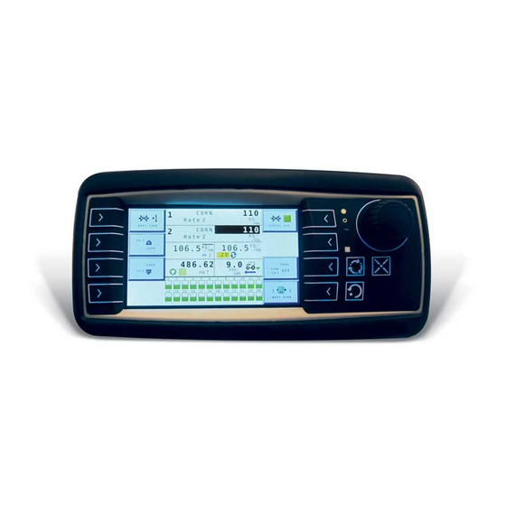
OPERATOR’S MANUAL A virtual terminal with 7” color display features a touch screen in lieu of rotary dial and hard keys for menu navigation. Figure 2 IntelliAg MVT Virtual Terminal 7” Display PLANTER CONTROL MODULE (PCM) Figure 3 Planter Control Module 7.45”... -
Page 10: Working Set Member (Wsmb) Module (Optional)
Terminal mounting kit includes: • Terminal mounting plate • RAM Mount • Bolts to secure mounting plate to RAM mount Nitro Software, Inc. SYSTEM COMPONENTS / 5 IntelliAg MVT 100 Portable Document Lane 11001-1643A-201411 Wonderland... - Page 11 SAE screws (included) 2. Attach terminal mounting plate to the virtual terminal and RAM mount. Figure 7 Terminal Bracket Insert 4 Mount Metric screws holes Opening Nitro Software, Inc. 6 / SYSTEM COMPONENTS IntelliAg MVT 100 Portable Document Lane 11001-1643A-201411 Wonderland...
- Page 12 4 attachment Attachment holes and connector Holes (3) opening Figure 9 Terminal Bracket and RAM Mount Secure VT and VT bracket to RAM mount using 3 screws Nitro Software, Inc. SYSTEM COMPONENTS IntelliAg MVT 100 Portable Document Lane 11001-1643A-201411 Wonderland...
- Page 13 Page 13 OPERATOR’S MANUAL Nitro Software, Inc. 8 / SYSTEM COMPONENTS IntelliAg MVT 100 Portable Document Lane 11001-1643A-201411 Wonderland...
-
Page 14: Component Installation
4. Mount with the label side of module facing out. Do not mount with the connector facing up (see Caution). Nitro Software, Inc. COMPONENT INSTALLATION / 9 IntelliAg MVT 100 Portable Document Lane 11001-1643A-201411 Wonderland... -
Page 15: Working Set Member (Wsmb) Module
Ensure that module connectors do not face upward when implement is in a folded position as well. 3. Mount with the label side of the module facing out. Nitro Software, Inc. 10 / COMPONENT INSTALLATION IntelliAg MVT 100 Portable Document Lane 11001-1643A-201411 Wonderland... - Page 16 1/4 NUT 1/4 SPLIT LOCKWASHER IMPLEMENT FRAME OR SUPPORT 1/4 x 20 THREADED "U" BOLT OR 1/4 FLAT WASHER OTHER FASTENING DEVICE 1/4 NUT 1/4 SPLIT LOCKWASHER Nitro Software, Inc. COMPONENT INSTALLATION IntelliAg MVT 100 Portable Document Lane 11001-1643A-201411 Wonderland...
- Page 17 10. Coil and secure any unused sensor connections. 11. The WSMB Module harness can accept a standard DICKEY-john PM style planter harness (single round 37-pin connector) or an SE style planter harness (1 gray 12-pin, 1 black 12-pin rectangular connector) depending on the WSMB harness.
-
Page 18: Connecting Cab/Terminal Harnessing
4. Connect the module harness to the mating connectors of the Implement CAN harness and then connect the module to the harness. The PCM module uses a 30 and 18-way connector with a jackscrew to Nitro Software, Inc. COMPONENT INSTALLATION / 13 IntelliAg MVT 100 Portable Document Lane 11001-1643A-201411 Wonderland... -
Page 19: Cab Harnessing Diagram
Mounting Chassis Bracket Ground 472940120 Tractor Cab Terminal Harness Power Harness Terminator 472940130 467980450 467980126 IntelliAg MVT 472940110 Ignition +12VDC To Implement Off/Auto NOTE: This wire Flush Switch must be connected Harness (optional future to switched +12VDC implementation) Nitro Software, Inc. -
Page 20: Implement Harnessing Diagrams
If no Implement Lift Switch 4 Sensor is used, connect the leads together 464820510 Air Pressure Radar Speed Planter Sensor x3 Sensor-Labeled Output GND Speed 46682-0920S1 Module 46798200051 Nitro Software, Inc. COMPONENT INSTALLATION / 15 IntelliAg MVT 100 Portable Document Lane 11001-1643A-201411 Wonderland... - Page 21 Terminator harness (Connect CAN terminator if this Standard Dj PM Style is the last module on Planter Harness the CAN bus) Nitro Software, Inc. 16 / COMPONENT INSTALLATION IntelliAg MVT 100 Portable Document Lane 11001-1643A-201411 Wonderland...
-
Page 22: Sensor Installation
SEED SENSORS The system is compatible with all existing DICKEY-john seed sensors. Seed sensors may be connected to the PCM module and all WSMB planter monitor modules. Any number of sensors up to the maximum capacity of the module may be connected. -
Page 23: Hopper Level Sensors
HOPPER 1-3. RPM SENSORS The system is compatible with all existing DICKEY-john RPM sensors. Two RPM sensors may be connected to the PCM module. The sensor is connected to the actuator harness. The RPM sensor connection is labeled RPM 1-2. -
Page 24: Virtual Terminal Features
7. USB port Figure 19 Virtual Terminal 4” Display 2. Rotary 7. USB Port 3. Soft Keys Knob Terminal Bracket Display Screen 4. Home 5. Screen Toggle Escape Nitro Software, Inc. VIRTUAL TERMINAL FEATURES IntelliAg MVT 100 Portable Document Lane 11001-1643A-201411 Wonderland... -
Page 25: Hard Keys
HOME BUTTON Captures a screen shot of the currently displayed window and saves to a USB device. This screen shot can be sent to DICKEY-john technical support team for troubleshooting purposes. SCREEN TOGGLE BUTTON Toggles between the two primary main screens of the terminal: 1. - Page 26 Returns to previous screen and does not save changes made at the keypad 4. Press the Check button to save selection and return to previous screen. Nitro Software, Inc. VIRTUAL TERMINAL FEATURES / 21 IntelliAg MVT 100 Portable Document Lane 11001-1643A-201411 Wonderland...
- Page 27 OPERATOR’S MANUAL Figure 21 Keypad Entry 1. Turn dial to select numeric value. Selected item highlights in green. 2. Push in dial to open keypad. Nitro Software, Inc. 22 / VIRTUAL TERMINAL FEATURES IntelliAg MVT 100 Portable Document Lane 11001-1643A-201411 Wonderland...
- Page 28 6. Press the Check button to accept selection and return to the previous screen. Figure 22 Keyboard Types Default Keyboard All Caps Keyboard Numeric Keyboard Characters Keyboard Nitro Software, Inc. VIRTUAL TERMINAL FEATURES IntelliAg MVT 100 Portable Document Lane 11001-1643A-201411 Wonderland...
-
Page 29: 7" Display User Interface
Figure 23 7” Virtual Terminal Display (modify) 5. USB Port 2. Touch Screen buttons Terminal Bracket 1. Display screen 4. Screen 3. Escape Toggle Nitro Software, Inc. 24 / VIRTUAL TERMINAL FEATURES IntelliAg MVT 100 Portable Document Lane 11001-1643A-201411 Wonderland... -
Page 30: Virtual Terminal Setup
– Turn the rotary dial clockwise or counterclockwise to adjust the bar until the desired setting is reached. Figure 24 Virtual Terminal Setup Screen Nitro Software, Inc. VIRTUAL TERMINAL SETUP / 25 IntelliAg MVT 100 Portable Document Lane 11001-1643A-201411 Wonderland... -
Page 31: Brightness Contrast
1. Language choices are identified by the country flag. An abbreviated identifier of the selected language displays next to the language window. Nitro Software, Inc. 26 / VIRTUAL TERMINAL SETUP IntelliAg MVT 100 Portable Document Lane 11001-1643A-201411 Wonderland... -
Page 32: Unit Measurement
Main Work screen. If the ISOBUS button is not selected and the rotary dial pressed, the changes will NOT be saved. Nitro Software, Inc. VIRTUAL TERMINAL SETUP / 27 IntelliAg MVT 100 Portable Document Lane 11001-1643A-201411 Wonderland... -
Page 33: Date/Time
Main Work screen. If the ISOBUS button is not selected and the rotary dial pressed, the changes will NOT be saved. Figure 29 Date and Time Increase/ Decrease buttons Nitro Software, Inc. 28 / VIRTUAL TERMINAL SETUP IntelliAg MVT 100 Portable Document Lane 11001-1643A-201411 Wonderland... -
Page 34: Isobus
Page 34 OPERATOR’S MANUAL ISOBUS The ISOBUS screen should only be used for troubleshooting purposes with the guidance of DICKEY-john technical support. 1. Deletes all object pools. 2. Deletes the latest object pool. Figure 30 ISOBUS INFORMATION The Information screen displays the module software versions connected to the system and is typically used for troubleshooting. - Page 35 Page 35 OPERATOR’S MANUAL Nitro Software, Inc. 30 / VIRTUAL TERMINAL SETUP IntelliAg MVT 100 Portable Document Lane 11001-1643A-201411 Wonderland...
-
Page 36: Virtual Terminal System Modes
The Target Rate for a channel can be adjusted by using the Inc/Dec buttons described below. • The channel’s Inc/Dec buttons, as well as the ON/OFF buttons, display the current channel label. Nitro Software, Inc. VIRTUAL TERMINAL SYSTEM MODES / 31 IntelliAg MVT 100 Portable Document Lane 11001-1643A-201411 Wonderland... - Page 37 Channel Setup mode. The active channel is displayed in the button text. If the button text is OFF, this is the action that occurs when the button is pressed. Nitro Software, Inc. 32 / VIRTUAL TERMINAL SYSTEM MODES IntelliAg MVT 100 Portable Document Lane 11001-1643A-201411 Wonderland...
-
Page 38: Setup (Top Menu) Mode
All user-entered constants relating to general planter monitor functions are accessed on this screen. NEXT PAGE Displays the next available Setup screen and associated buttons. WORK SCREEN Displays the Main Work screen. Nitro Software, Inc. VIRTUAL TERMINAL SYSTEM MODES / 33 IntelliAg MVT 100 Portable Document Lane 11001-1643A-201411 Wonderland... - Page 39 A listing of previous alarms that have occurred display on screen. There is no user-entered data on this screen. Not all alarms are recorded in the alarm log. Nitro Software, Inc. 34 / VIRTUAL TERMINAL SYSTEM MODES IntelliAg MVT 100 Portable Document Lane 11001-1643A-201411 Wonderland...
-
Page 40: User Levels
6. Press the Work Screen button to return to the Main Work screen. The system will return to the previous set level at each power cycle until changed at the Password screen. Nitro Software, Inc. USER LEVELS / 35 IntelliAg MVT 100 Portable Document Lane 11001-1643A-201411 Wonderland... - Page 41 Page 41 OPERATOR’S MANUAL Figure 34 Changing User Level Nitro Software, Inc. 36 / USER LEVELS IntelliAg MVT 100 Portable Document Lane 11001-1643A-201411 Wonderland...
-
Page 42: User Level 2 (Oem/Dealer)
– Enter the first digit as 2 for User Level 2. – For the next five digits, enter the Planter Control Module Serial Number taken from the PCM or Information screen (example S/N 11685). Nitro Software, Inc. USER LEVELS / 37 IntelliAg MVT 100 Portable Document Lane 11001-1643A-201411 Wonderland... - Page 43 11. If a red bar appears in the top box that displays the chosen number, the red Cancel button must be pressed and entry started again. 12. At the Password screen, press the OK button to finalize. Nitro Software, Inc. 38 / USER LEVELS IntelliAg MVT 100 Portable Document Lane 11001-1643A-201411 Wonderland...
-
Page 44: Material Setup
NOTE: The whole name can be entered at one time using the Enter a Material Name virtual keyboard unlike the keyboard used to enter a password. CORN Caps Nitro Software, Inc. MATERIAL SETUP / 39 IntelliAg MVT 100 Portable Document Lane 11001-1643A-201411 Wonderland... -
Page 45: Define Material Parameters
All seeding control channels MUST instructions. be disabled in this configuration and/or no rows assigned to those seeding channels. Nitro Software, Inc. 40 / MATERIAL SETUP IntelliAg MVT 100 Portable Document Lane 11001-1643A-201411 Wonderland... -
Page 46: Planter Control Material Type
Increment/Decrement buttons. The target rate increases or decreases based on the Inc/Dec % value set at the Material Configuration screen (Figure 40). Nitro Software, Inc. MATERIAL SETUP / 41 IntelliAg MVT 100 Portable Document Lane 11001-1643A-201411 Wonderland... -
Page 47: Preset Method Enabled
Material Setup Screen-Preset Method Enabled CORN With Preset enabled, target rate adjusts based on the rates entered at the Material Setup CORN screen. CORN CORN Nitro Software, Inc. 42 / MATERIAL SETUP IntelliAg MVT 100 Portable Document Lane 11001-1643A-201411 Wonderland... -
Page 48: Target Rate
The maximum or minimum RPM at which the seed disc will operate. The control will not allow the seed disc to rotate faster than the Disc High or Low Limit setting. Nitro Software, Inc. MATERIAL SETUP / 43 IntelliAg MVT 100 Portable Document Lane 11001-1643A-201411 Wonderland... -
Page 49: Material Level Alarm
Every 4th Row On X-XXX-XX Every 4th Row On -XXX-XXX Every 4th Row On --XX--XX--XX Twin Rows -XX--XX--XX- Twin Rows XX--XX--XX-- Twin Rows X--XX--XX--X Twin Rows Nitro Software, Inc. 44 / MATERIAL SETUP IntelliAg MVT 100 Portable Document Lane 11001-1643A-201411 Wonderland... -
Page 50: Row Fail Rate
The target rate increases or decreases based on the Inc/Dec % value set at the Material Configuration screen (Figure 40). TARGET RATE Target Rate establishes the desired rate of application in pounds per acre (kg/Ha). Nitro Software, Inc. MATERIAL SETUP / 45 IntelliAg MVT 100 Portable Document Lane 11001-1643A-201411 Wonderland... -
Page 51: Maximum Rate
If density is unknown, a value of 1 can be entered to perform a spreader constant. This will place the channel into a pure pulse/ft granular system. Nitro Software, Inc. 46 / MATERIAL SETUP IntelliAg MVT 100 Portable Document Lane 11001-1643A-201411 Wonderland... -
Page 52: Spreader Constant
The Preset Method table allows 10 user-defined target rates to be entered. When enabled, target rates can be adjusted from the Main Work screen using the Increment/Decrement buttons (Figure 41). Nitro Software, Inc. MATERIAL SETUP / 47 IntelliAg MVT 100 Portable Document Lane 11001-1643A-201411 Wonderland... -
Page 53: Preset Method Disabled
2%, the maximum rate of 101 will not be met because the % increase of 2% would exceed the 101 maximum rate limit. Figure 46 Liquid Control Material Type Screen 2 Nitro Software, Inc. 48 / MATERIAL SETUP IntelliAg MVT 100 Portable Document Lane 11001-1643A-201411 Wonderland... -
Page 54: Low Flow Limit
The Material Level alarm sets the gallons left in the tank to trigger an alarm alerting of low liquid levels. The entered value is an estimate in gallons. Nitro Software, Inc. MATERIAL SETUP / 49 IntelliAg MVT 100 Portable Document Lane 11001-1643A-201411 Wonderland... - Page 55 Page 55 OPERATOR’S MANUAL Nitro Software, Inc. 50 / MATERIAL SETUP IntelliAg MVT 100 Portable Document Lane 11001-1643A-201411 Wonderland...
-
Page 56: Control Channel Setup
4. Push in the rotary button to select or change the value. 5. Push in the rotary button again to accept the change. 6. Press the More button for additional parameters. Nitro Software, Inc. CONTROL CHANNEL SETUP / 51 IntelliAg MVT 100 Portable Document Lane 11001-1643A-201411 Wonderland... -
Page 57: Planter Control Channel
Drive Frequency specifies the frequency for the proportional valve being used. The recommended setting for this option should be specified from the specific valve manufacturer. NOTE: DICKEY-john proportional valves operate at 100 hz. Nitro Software, Inc. 52 / CONTROL CHANNEL SETUP... -
Page 58: Gear Ratio
SENSOR CONSTANT Sensor Constant establishes the number of pulses for one revolution of the application rate sensor. If a standard DICKEY-john application rate sensor is used, the value should be set to 360.0. Figure 48... -
Page 59: Precharge Time
• The system will delay the channel shutdown if the master/control switch is turned OFF and the implement is in the down position. Nitro Software, Inc. 54 / CONTROL CHANNEL SETUP IntelliAg MVT 100 Portable Document Lane 11001-1643A-201411 Wonderland... -
Page 60: Control Channel Setup Continued
6. Press the Start button. The seed meters will turn for 1 revolution, then stop. 7. Pressing the Stop button will also terminate the test. Figure 49 Fill Disk Screen for One Control Channel Nitro Software, Inc. CONTROL CHANNEL SETUP / 55 IntelliAg MVT 100 Portable Document Lane 11001-1643A-201411 Wonderland... -
Page 61: Granular Control Channel
A valve, usually hydraulic, which varies the oil flow to a hydraulic motor proportioned to electric current supplied. This type of valve consists of a flow cartridge and coil assembly. Nitro Software, Inc. 56 / CONTROL CHANNEL SETUP IntelliAg MVT 100 Portable Document Lane 11001-1643A-201411 Wonderland... -
Page 62: Drive Frequency
Establishes the number of pulses for one revolution of the metering unit. If a must be determined for sensors standard DICKEY-john application rate sensor is used, the value should be other than DICKEY-john. set to 360.0. -
Page 63: Number Of Seed Rows
1. At the Control Channel screen, enter a Precharge time. A Precharge Time must be entered before the Precharge Ground Speed feature displays on the Ground Speed Setup screen (Refer to Ground Speed Setup section). Nitro Software, Inc. 58 / CONTROL CHANNEL SETUP IntelliAg MVT 100 Portable Document Lane 11001-1643A-201411 Wonderland... -
Page 64: Delay Time
The control channel delays after the master switch has been turned • A delay also occurs and then shutdowns the control channel when the master switch is turned OFF. Nitro Software, Inc. CONTROL CHANNEL SETUP / 59 IntelliAg MVT 100 Portable Document Lane 11001-1643A-201411 Wonderland... -
Page 65: Liquid Flow Channel
DRIVE TYPE PWM (Pulse Width Modulation) NOTE: DICKEY-john Servo valves operate at 40 Hz; DICKEY-john A proportional valve regulating hydraulics and varies the oil flow to a Proportional valves operate at hydraulic motor proportioned to electric current supplied. This type of valve 100 Hz. -
Page 66: Drive Frequency
Valve locking is also used for tank agitation. CHANNEL WIDTH Channel Width requires a manual entry of the width of the liquid sprayed. Nitro Software, Inc. CONTROL CHANNEL SETUP / 61 IntelliAg MVT 100 Portable Document Lane 11001-1643A-201411 Wonderland... -
Page 67: Flush Enable
• The system will delay the channel shutdown if the master switch is turned OFF and the implement is in the down position. Nitro Software, Inc. 62 / CONTROL CHANNEL SETUP IntelliAg MVT 100 Portable Document Lane 11001-1643A-201411 Wonderland... - Page 68 OFF. above if the system has been purchased direct from the original equipment manufacturer. Refer to the manufacturer’s operator manual for further instruction. Nitro Software, Inc. CONTROL CHANNEL SETUP / 63 IntelliAg MVT 100 Portable Document Lane 11001-1643A-201411 Wonderland...
- Page 69 Page 69 OPERATOR’S MANUAL Nitro Software, Inc. 64 / CONTROL CHANNEL SETUP IntelliAg MVT 100 Portable Document Lane 11001-1643A-201411 Wonderland...
-
Page 70: Valve Calibration
When the START key is engaged, the machine will become operational. All necessary precautions must be taken to ensure user safety. Failure to practice all necessary caution may result in serious injury or death. Nitro Software, Inc. VALVE CALIBRATION / 65 IntelliAg MVT 100 Portable Document Lane 11001-1643A-201411 Wonderland... - Page 71 12. When the calibration is complete, the control shuts down automatically. All calibration data is automatically stored. Nitro Software, Inc. 66 / VALVE CALIBRATION IntelliAg MVT 100 Portable Document Lane 11001-1643A-201411 Wonderland...
-
Page 72: Granular Control Calibration
9. Press the Start button and the valve calibration immediately begins. The calibration runs using the new max flow value. Nitro Software, Inc. VALVE CALIBRATION / 67 IntelliAg MVT 100 Portable Document Lane 11001-1643A-201411 Wonderland... -
Page 73: Granular Control Valve Calibration
7. Press the Shaft Turn button to fill seed/fertilizer metering system before starting calibration. 8. At the Calibration screen, enter the following values: Density-Enter product weight per volume in 1 lbs/ft3. Nitro Software, Inc. 68 / VALVE CALIBRATION IntelliAg MVT 100 Portable Document Lane 11001-1643A-201411 Wonderland... -
Page 74: Spreader Constants Defined
, Lbs/bu.) If not known, enter a value of 1 lbs/ft Spreader Constant Determines how many pulses the application rate sensor produces per volume of material discharged. Nitro Software, Inc. VALVE CALIBRATION / 69 IntelliAg MVT 100 Portable Document Lane 11001-1643A-201411 Wonderland... -
Page 75: Shaft Turn
The Shaft Turn button turns the shaft one (1) gear revolution and fills the seed meter for instant seed flow when the control is turned on. Nitro Software, Inc. 70 / VALVE CALIBRATION IntelliAg MVT 100 Portable Document Lane 11001-1643A-201411 Wonderland... -
Page 76: Liquid Flow Calibration
9. Press the Start button and the valve calibration immediately begins. The calibration runs using the new max flow value. Figure 58 Limit Output Nitro Software, Inc. VALVE CALIBRATION / 71 IntelliAg MVT 100 Portable Document Lane 11001-1643A-201411 Wonderland... -
Page 77: Perform A Valve Calibration
3. After spraying a few hundred gallons but before the load is empty, stop the calibration. 4. Weigh the load again. 5. Calculate gallons dropped. Nitro Software, Inc. 72 / VALVE CALIBRATION IntelliAg MVT 100 Portable Document Lane 11001-1643A-201411 Wonderland... -
Page 78: Perform A Liquid Flow Catch Test
6. Enter amount (gallons) dispensed in the Total Amount field. 7. Press Save button to accept the selection. 8. The system automatically calculates and saves the new K Factor for this material. Nitro Software, Inc. VALVE CALIBRATION / 73 IntelliAg MVT 100 Portable Document Lane 11001-1643A-201411 Wonderland... - Page 79 Page 79 OPERATOR’S MANUAL Figure 60 K Factor Nitro Software, Inc. 74 / VALVE CALIBRATION IntelliAg MVT 100 Portable Document Lane 11001-1643A-201411 Wonderland...
-
Page 80: System Configuration
IMPORTANT: If an implement uses more than one module type, mount the modules on the implement in serial number order starting on the left side and proceeding to the right. Nitro Software, Inc. SYSTEM CONFIGURATION / 75 IntelliAg MVT 100 Portable Document Lane 11001-1643A-201411 Wonderland... -
Page 81: Perform An Auto Configuration
IMPORTANT: Double check each sensor configuration to verify correct numbering. RPM sensors must be configured manually. Nitro Software, Inc. 76 / SYSTEM CONFIGURATION IntelliAg MVT 100 Portable Document Lane 11001-1643A-201411 Wonderland... -
Page 82: Module & Sensor Installation Examples
Module Address 1. No Working Set Member is utilized. Figure 62 12 Row Installation Example (PCM only) Module Configuration Screen Seed Sensor Configuration Screen 1 - 12 11685 Nitro Software, Inc. SYSTEM CONFIGURATION / 77 IntelliAg MVT 100 Portable Document Lane 11001-1643A-201411 Wonderland... -
Page 83: Row Installation
Figure 63 24 Row Installation Example Module Configuration Screen Seed Sensor Configuration Screen MT - PCM MT - PCM 1-12 13-24 11685 Working Set Member Nitro Software, Inc. 78 / SYSTEM CONFIGURATION IntelliAg MVT 100 Portable Document Lane 11001-1643A-201411 Wonderland... -
Page 84: Row Installation
Working Set Member Module Address 1 Rows 1-12 FRONT Working Set Member Working Set Member Module Address 4 Module Address 3 Rows 37-48 Rows 25-36 BACK Nitro Software, Inc. SYSTEM CONFIGURATION / 79 IntelliAg MVT 100 Portable Document Lane 11001-1643A-201411 Wonderland... -
Page 85: System Configuration Continued
Auto Update Width is enabled. If the adjusted values are not correct, disable the Auto Update Width feature and manually enter a row width and implement width. Nitro Software, Inc. 80 / SYSTEM CONFIGURATION IntelliAg MVT 100 Portable Document Lane 11001-1643A-201411 Wonderland... -
Page 86: Implement Width
Individual rows in the Row Setup screen can still be manually edited to Population, Blockage, or Off before or after a pattern is selected. The pattern setting, when selected, will override previous individual existing row settings. Nitro Software, Inc. SYSTEM CONFIGURATION / 81 IntelliAg MVT 100 Portable Document Lane 11001-1643A-201411 Wonderland... -
Page 87: Blockage Pattern
Even rows use Recon and odd rows use Hi Rate Blockage • Every 2nd Row Pop (B_B_B_) Population = - Even rows use Hi Rate and odd rows use Recon Nitro Software, Inc. 82 / SYSTEM CONFIGURATION IntelliAg MVT 100 Portable Document Lane 11001-1643A-201411 Wonderland... -
Page 88: Row Monitor Setup
If the value is set to 10, a row must be in a High or Low Population intervals does not provide any Alarm condition continuously for 10 seconds before the alarm is issued. delay at all. Nitro Software, Inc. SYSTEM CONFIGURATION / 83 IntelliAg MVT 100 Portable Document Lane 11001-1643A-201411 Wonderland... -
Page 89: Population Adjust
Both values are adjustable allowing for numerous combinations. The default value is 2/1 that indicates a row failure threshold of 2 seeds in 1 second. Nitro Software, Inc. 84 / SYSTEM CONFIGURATION IntelliAg MVT 100 Portable Document Lane 11001-1643A-201411 Wonderland... -
Page 90: Row Assignment
– Confirm that all harnessing and sensors are connected properly. Refer to the Troubleshooting section for further information. Nitro Software, Inc. SYSTEM CONFIGURATION / 85 IntelliAg MVT 100 Portable Document Lane 11001-1643A-201411 Wonderland... - Page 91 Page 91 OPERATOR’S MANUAL Nitro Software, Inc. 86 / SYSTEM CONFIGURATION IntelliAg MVT 100 Portable Document Lane 11001-1643A-201411 Wonderland...
-
Page 92: Accessory Sensors
TIP: Press the Top Menu/Auto Config button to auto populate pressure sensors and hopper sensors. Figure 69 Accessory Assignment Screen MT - PCM MT - PCM Nitro Software, Inc. ACCESSORY SENSORS / 87 IntelliAg MVT 100 Portable Document Lane 11001-1643A-201411 Wonderland... -
Page 93: Pressure Sensor Setup
Establishes the delay between the detection of a high or low pressure alarm condition and the resulting alarm display. The value is entered in seconds. Nitro Software, Inc. 88 / ACCESSORY SENSORS IntelliAg MVT 100 Portable Document Lane 11001-1643A-201411 Wonderland... -
Page 94: Pressure Filter
3. Press the OK button and push in rotary dial to accept. – Press the Next RPM button to set parameters for additional sensor. Figure 71 RPM Setup Screen MT - PCM MT - PCM Nitro Software, Inc. ACCESSORY SENSORS / 89 IntelliAg MVT 100 Portable Document Lane 11001-1643A-201411 Wonderland... -
Page 95: High/Low Alarm
DISABLED will disable the function. The control channels continue to operate normally regardless of the RPM value. However, when the low RPM state occurs, the information alarm still occurs. Nitro Software, Inc. 90 / ACCESSORY SENSORS IntelliAg MVT 100 Portable Document Lane 11001-1643A-201411 Wonderland... -
Page 96: Hopper Sensor Setup
2. Use the rotary dial to highlight the yellow input box. 3. Push in the rotary dial to select or enter a value. 4. Push in the rotary dial to accept. Nitro Software, Inc. ACCESSORY SENSORS / 91 IntelliAg MVT 100 Portable Document Lane 11001-1643A-201411 Wonderland... -
Page 97: Logic Level
The value is entered in seconds. CHANNEL Assigns the hopper sensor to a specific control channel. Nitro Software, Inc. 92 / ACCESSORY SENSORS IntelliAg MVT 100 Portable Document Lane 11001-1643A-201411 Wonderland... -
Page 98: Ground Speed Setup
ON at the programmed speed. This value can be set to any speed within the delivery capabilities of the system. Nitro Software, Inc. GROUND SPEED SETUP / 93 IntelliAg MVT 100 Portable Document Lane 11001-1643A-201411 Wonderland... -
Page 99: Gspd Constant
The control will operate at this speed until actual ground speed rises above the minimum override speed or the actual speed drops below the shutoff speed. Nitro Software, Inc. 94 / GROUND SPEED SETUP IntelliAg MVT 100 Portable Document Lane 11001-1643A-201411 Wonderland... -
Page 100: Master Switch Timeout
An Alarm Cancel button allows the alarm to be deactivated during the current power cycle. If an implement lift switch is not required, this function should be disabled. Nitro Software, Inc. GROUND SPEED SETUP / 95 IntelliAg MVT 100 Portable Document Lane 11001-1643A-201411 Wonderland... -
Page 101: Speed Calibration
OPERATOR’S MANUAL SPEED CALIBRATION Ground speed is the rate in MPH (Km/h) as measured by the ground speed NOTE: Older DICKEY-john ground speed calibrations had a default sensor. The number reflects the number of pulses generated by the ground value of 6096, which is the speed sensor while traveling a distance of 400 feet (100 meters). -
Page 102: Section Control -Manual
The Output Numbers (#s) value is automatically sequenced for each module based on the module address value. Nitro Software, Inc. SECTION CONTROL -MANUAL / 97 IntelliAg MVT 100 Portable Document Lane 11001-1643A-201411 Wonderland... -
Page 103: Assign Rows To Outputs
2. Enter the number of rows to be turned on/off by each output. The row numbers are sequentially assigned to the output number based on the # of rows entered. Figure 79 Assign Rows Screen Nitro Software, Inc. 98 / SECTION CONTROL -MANUAL IntelliAg MVT 100 Portable Document Lane 11001-1643A-201411 Wonderland... -
Page 104: Assign Shutoff Switches
2. Enter the switch number that controls the on/off status of each module output. 3. Press the Link Channel input box to link a channel to a switch (checkmark). Figure 80 Assign Shutoff Switches Screen Nitro Software, Inc. SECTION CONTROL -MANUAL / 99 IntelliAg MVT 100 Portable Document Lane 11001-1643A-201411 Wonderland... -
Page 105: Boom Assignment-Liquid
1. At the Boom Setup screen, press the Boom Width button. 2. Press the Channel input boxes to enter the channel to control a section. Nitro Software, Inc. 100 / SECTION CONTROL -MANUAL IntelliAg MVT 100 Portable Document Lane 11001-1643A-201411 Wonderland... -
Page 106: Boom Switch Assignment
1. At the Boom Setup Screen, press the Boom Assign button. 2. Enter the switch to control a section. Figure 83 Boom Switch Assignment Nitro Software, Inc. SECTION CONTROL -MANUAL / 101 IntelliAg MVT 100 Portable Document Lane 11001-1643A-201411 Wonderland... - Page 107 Page 107 OPERATOR’S MANUAL Nitro Software, Inc. 102 / SECTION CONTROL -MANUAL IntelliAg MVT 100 Portable Document Lane 11001-1643A-201411 Wonderland...
-
Page 108: Customizing The Work Screen
4. Push in the knob to select and display data item choices. 5. Scroll using the knob and push in to select. 6. Press the Next Screen button to create 2 additional work screens. Nitro Software, Inc. CUSTOMIZING THE WORK SCREEN / 103 IntelliAg MVT 100 Portable Document Lane 11001-1643A-201411 Wonderland... -
Page 109: Clearing Data Item Accumulators
Main Work screen. A maximum of 2 lines and 24 columns can display. Default displays 1 line and 24 columns. Nitro Software, Inc. 104 / CUSTOMIZING THE WORK SCREEN IntelliAg MVT 100 Portable Document Lane 11001-1643A-201411 Wonderland... -
Page 110: Spacing Quality Bar Graph
Data Items and Function section to display as a data item on the Main Work screen. – Seed singulation maximum is 72 rows of seed input Nitro Software, Inc. CUSTOMIZING THE WORK SCREEN / 105 IntelliAg MVT 100 Portable Document Lane 11001-1643A-201411 Wonderland... -
Page 111: Return System Active Delay
The delay time starts when the master/control switch is turned ON and the implement is in a down position. Delay time will not start unless both of these conditions are met. IMPORTANT: This feature only operates with DICKEY-john virtual terminals. DATA ITEMS AND FUNCTIONS Data items are display parameters that can be selected to appear on the Main Work screen. - Page 112 This Data Item will display on an entire row of the Work screen. Nitro Software, Inc. CUSTOMIZING THE WORK SCREEN / 107 IntelliAg MVT 100 Portable Document Lane 11001-1643A-201411 Wonderland...
- Page 113 This Data Item displays on an entire row of the Work screen. Nitro Software, Inc. 108 / CUSTOMIZING THE WORK SCREEN IntelliAg MVT 100 Portable Document Lane 11001-1643A-201411 Wonderland...
- Page 114 This Data Item displays on an entire row of the Work screen. Nitro Software, Inc. CUSTOMIZING THE WORK SCREEN / 109 IntelliAg MVT 100 Portable Document Lane 11001-1643A-201411 Wonderland...
- Page 115 Singulation Average displays the average percent seed singulation of the planter’s rows that are configured for population. Singulation refers to the portion of seeds planted individually rather than in groups. Nitro Software, Inc. 110 / CUSTOMIZING THE WORK SCREEN IntelliAg MVT 100 Portable Document Lane 11001-1643A-201411 Wonderland...
- Page 116 0.0 at any time. Current area is retained after power down. If no rows are configured, the Total Area Accumulator will use the largest AC T 0 . 0 0 channel width. Nitro Software, Inc. CUSTOMIZING THE WORK SCREEN / 111 IntelliAg MVT 100 Portable Document Lane 11001-1643A-201411 Wonderland...
- Page 117 The current sensor is identified by the number displayed above the RPM symbol (planter control, granular seeding, granular fertilizer) or GPM symbol (liquid flow). Nitro Software, Inc. 112 / CUSTOMIZING THE WORK SCREEN IntelliAg MVT 100 Portable Document Lane 11001-1643A-201411 Wonderland...
- Page 118 Channels 1 - 2 Material Accum displays the current accumulated material for Channels 1 - 2. Material is accumulated according to the applied rate. Does not function if channel is planter control. Nitro Software, Inc. CUSTOMIZING THE WORK SCREEN / 113 IntelliAg MVT 100 Portable Document Lane 11001-1643A-201411 Wonderland...
- Page 119 HOPPER LEVEL STATUS SCAN Hopper Level Status Scan scans through all the hopper level sensors in the system and indicates an empty or nonempty status. Nitro Software, Inc. 114 / CUSTOMIZING THE WORK SCREEN IntelliAg MVT 100 Portable Document Lane 11001-1643A-201411 Wonderland...
-
Page 120: System Tests
TEST TARGET POPULATION Test Target Pop is the seed rate at which the test is performed. This value is the current target rate and is automatically populated. Nitro Software, Inc. SYSTEM TESTS / 115 IntelliAg MVT 100 Portable Document Lane 11001-1643A-201411 Wonderland... -
Page 121: Test Seed Count
Seed Count button. – Stop button suspends the test – Next Rows button displays next series of rows – Count Reset button clears seed count Nitro Software, Inc. 116 / SYSTEM TESTS IntelliAg MVT 100 Portable Document Lane 11001-1643A-201411 Wonderland... -
Page 122: Test Ground Speed
REMOTE TEST SWITCH A momentary switch can be purchased from DICKEY-john that allows the the control to be turned on/off during the Continuous and 5 Rev tests. The switch allows the operator to go back to the implement to perform the test and investigate mechanical issues or perform seed counts instead of performing the test inside the cab from the Virtual Terminal. - Page 123 OPERATOR’S MANUAL Remote test switch part number is 464210515S1. Once testing is complete, the remote test switch should be disconnected to prevent accidental control engagement. Nitro Software, Inc. 118 / SYSTEM TESTS IntelliAg MVT 100 Portable Document Lane 11001-1643A-201411 Wonderland...
-
Page 124: Operation
RPM, set the master/control switch to the On position. All enabled control channels will begin controlling at the current ground speed. All accumulators will begin recording data. Nitro Software, Inc. OPERATION / 119 IntelliAg MVT 100 Portable Document Lane 11001-1643A-201411 Wonderland... -
Page 125: Stop
Figure 92 Main Work Screen Functions Target Rate Preset Enabled Target Rate CORN Inc/Dec % Implement Accumulator Lift Up/Down Reset Indicator Row Status Indicators Nitro Software, Inc. 120 / OPERATION IntelliAg MVT 100 Portable Document Lane 11001-1643A-201411 Wonderland... -
Page 126: Operate Screen Symbols
Row off by control to channel and seeds detected Not planting Row off manually High Population Master Switch or pattern Blockage Low Population Planting at desired rate Nitro Software, Inc. OPERATION / 121 IntelliAg MVT 100 Portable Document Lane 11001-1643A-201411 Wonderland... -
Page 127: Using The Precharge Feature
0. – The rate instrument populates with the word “CHARGE” and the countdown timer. – Timer displays how much precharge time is left before it aborts. Nitro Software, Inc. 122 / OPERATION IntelliAg MVT 100 Portable Document Lane 11001-1643A-201411 Wonderland... -
Page 128: Monitor Only Feature
– Material Name only appears when the channel is disabled and Monitor Only is selected. A material name is required to activate associated high and low population alarms. Nitro Software, Inc. OPERATION / 123 IntelliAg MVT 100 Portable Document Lane 11001-1643A-201411 Wonderland... -
Page 129: Linking Channels And Rates
4. Highlight the On/Off 1 box and select the linking symbol to control turn channel 1 and 2 on and off simultaneously. Figure 97 Linking Channel Rates Nitro Software, Inc. 124 / OPERATION IntelliAg MVT 100 Portable Document Lane 11001-1643A-201411 Wonderland... -
Page 130: System Accumulators
Reset Time button. SYSTEM ACTIVE AREA System Active Area is the accumulated area covered while the master/ control switch is on. System Active Area cannot be reset. Nitro Software, Inc. OPERATION / 125 IntelliAg MVT 100 Portable Document Lane 11001-1643A-201411 Wonderland... -
Page 131: Distance
2. Press the Stop Distance button to stop distance accumulation. 3. Press the Reset Distance button to reset the value back to 0.0. Nitro Software, Inc. 126 / OPERATION IntelliAg MVT 100 Portable Document Lane 11001-1643A-201411 Wonderland... -
Page 132: Diagnostics
3. Press the Next Page button. 4. Press the Diagnostics button. 5. At the Diagnostics screen, press the Control On button. Figure 99 Diagnostics Pulse Count Reset Nitro Software, Inc. OPERATION / 127 IntelliAg MVT 100 Portable Document Lane 11001-1643A-201411 Wonderland... - Page 133 Page 133 OPERATOR’S MANUAL Nitro Software, Inc. 128 / OPERATION IntelliAg MVT 100 Portable Document Lane 11001-1643A-201411 Wonderland...
-
Page 134: Import/Export Data
“Exporting Data..” appears at screen bottom. A successful data transfer will appear when complete. 7. The Import button will appear after a successful transfer. Figure 100 Export Data Nitro Software, Inc. IMPORT/EXPORT DATA / 129 IntelliAg MVT 100 Portable Document Lane 11001-1643A-201411 Wonderland... - Page 135 Validation” will appear at screen bottom. Importing Data Success appears when finished. 4. Press the Power button to reboot the terminal. Figure 101 Import Data Nitro Software, Inc. 130 / IMPORT/EXPORT DATA IntelliAg MVT 100 Portable Document Lane 11001-1643A-201411 Wonderland...
-
Page 136: Pom Software Upgrade
NOTE: Contact Technical Service for upgrade assistance if required 1. Power on terminal. at the DICKEY-john U.S. office 2. Insert USB memory device that has the software upgrade. at 1-800-632-3307 or the 3. An Update screen displays. Press the Update button. The update Europe office at begins with a status bar indicating load progress. - Page 137 Page 137 OPERATOR’S MANUAL Nitro Software, Inc. 132 / PCM SOFTWARE UPGRADE IntelliAg MVT 100 Portable Document Lane 11001-1643A-201411 Wonderland...
-
Page 138: Alarms
– The down arrow in the lower left at screen bottom signifies that more alarms are present and accessible by pressing the Previous or Next buttons. Figure 103 Alarm Log Nitro Software, Inc. ALARMS / 133 IntelliAg MVT 100 Portable Document Lane 11001-1643A-201411 Wonderland... -
Page 139: Alarm Detail
To reset the Alarm Log, press the Alarm Reset button. 1. Press YES button to clear. 2. Press NO button to return to Alarm Log Detail screen. Figure 105 Alarm Reset Nitro Software, Inc. 134 / ALARMS IntelliAg MVT 100 Portable Document Lane 11001-1643A-201411 Wonderland... -
Page 140: Troubleshooting & Alarm Codes
The following table describes the possible alarm conditions, causes, and remedies. For troubleshooting assistance, please contact our DICKEY-john U.S. Support Team at 1-800-637-3302 or the DICKEY-john Europe office at +33 1 41 19 21 80 or europe@dickey-john.com. Nitro Software, Inc. - Page 141 Page 141 OPERATOR’S MANUAL Nitro Software, Inc. 136 / TROUBLESHOOTING & ALARM CODES IntelliAg MVT 100 Portable Document Lane 11001-1643A-201411 Wonderland...
-
Page 142: Warranty
(011-33-141-192180). VT Out of Memory Alarm The ECU memory requirements are greater 1. Remove any unnecessary ECU’s than the Virtual Terminal can handle. 2. Contact DICKEY-john Technical Support (1-800-637-3302) or DICKEY-john Europe (011-33-141-192180) for updated hardware. Software Version Does 1. Occurs if new software is loaded and 1. - Page 143 3. Inspect module for damage. Replace if setup. necessary. 2. Defective seed sensor. 4. Fill with seed. 3. Defective module. 4. Running out of seed. Nitro Software, Inc. 138 / TROUBLESHOOTING & ALARM CODES IntelliAg MVT 100 Portable Document Lane 11001-1643A-201411 Wonderland...
- Page 144 Replace if necessary. Channel Invalid State 1. Internal system software error. 1. Cycle system power Off/On. If condition Alarm persists, contact DICKEY-john Technical Support (1-800-637-3302) or DICKEY-john Europe (011-22-141-192180). Nitro Software, Inc. TROUBLESHOOTING & ALARM CODES / 139...
- Page 145 3. Verify correct # HOPP setting for each 1. Defective hopper sensor. module. 2. Defective module or damaged module harness. 3. Additional hopper sensors detected. Nitro Software, Inc. 140 / TROUBLESHOOTING & ALARM CODES IntelliAg MVT 100 Portable Document Lane 11001-1643A-201411 Wonderland...
- Page 146 2. Acknowledge alarm and disable manual During this the control will run without or precharge to stop control. ground speed or without the implement down. Nitro Software, Inc. TROUBLESHOOTING & ALARM CODES / 141 IntelliAg MVT 100 Portable Document Lane 11001-1643A-201411 Wonderland...
- Page 147 2. Blown module harness fuse. 2. Inspect module harness fuse or replace. 3. Defective module. 3. Inspect identified module for damage or replace. Nitro Software, Inc. 142 / TROUBLESHOOTING & ALARM CODES IntelliAg MVT 100 Portable Document Lane 11001-1643A-201411 Wonderland...
- Page 148 2. Inspect PWM or Servo valve drivers for damage and replace if necessary. 3. Inspect identified module for damage and replace if necessary. Nitro Software, Inc. TROUBLESHOOTING & ALARM CODES / 143 IntelliAg MVT 100 Portable Document Lane 11001-1643A-201411 Wonderland...
- Page 149 Page 149 OPERATOR’S MANUAL Nitro Software, Inc. 144 / TROUBLESHOOTING & ALARM CODES IntelliAg MVT 100 Portable Document Lane 11001-1643A-201411 Wonderland...
- Page 150 Europe: DICKEY-john Europe S.A.S, 165, boulevard de Valmy, 92706 – Colombes – France TEL: 33 (0) 1 41 19 21 80, FAX: 33 (0) 1 47 86 00 07 WEB: www.dickey-john.eu Copyright 2014 DICKEY-john Corporation Specifications subject to change without notice.
Need help?
Do you have a question about the IntelliAg MVT and is the answer not in the manual?
Questions and answers