Advertisement
Quick Links
GIGABIT
SWITCH
Q
I
uick
nstallation
I N D U S T R I A L
Introduction
The
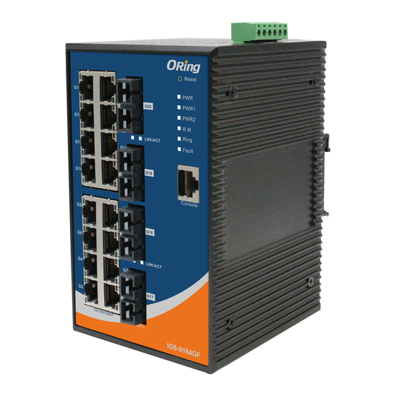
IGS-9164GF/FX series
is a managed industrial Ethernet switch with
16x10/100/1000Base-T(X) ports and 4 fixed optical fiber ports. The IGS-
9164GF provides 4x1000Base-X fiber ports and the IGS-9164FX provides
4x100Base-FX fiber ports. The cost-effective device with a high port density
can be managed centrally via web browsers, TELNET, Console or other
third-party SNMP software as well as Oring's proprietary Open-Vision
management utility. With complete support for Ethernet redundancy
protocols such as O-Ring (recovery time < 30ms over 250 units of
connection) and MSTP (RSTP/STP compatible), the devices can protect
your mission-critical applications from network interruptions or temporary
malfunctions with its fast recovery technology. Boasting a wide operating
o
o
temperature from -40 C to 75 C, the switch can meet the demanding
requirements of power substations and rolling stock applications.
Package Contents
The
IGS-9164GF/FX eries
are shipped with the following items. If any of
these items is missing or damaged, please contact your customer service
representative for assistance.
Contents
Pictures
IGS-9164GF/FX
CD
DIN-rail Kit
Wall-mount Kit
Console Cable
QIG
Preparation
Before you begin installing the switch, make sure you have all of the package
contents available and a PC with Microsoft Internet Explorer 6.0 or later, for
using web-based system management tools.
Safety & Warnings
Elevated Operating Ambient:
If installed in a closed or multi-unit rack
assembly, the operating ambient temperature of the rack environment may be
greater than room ambient. Therefore, consideration should be given to
installing the equipment in an environment compatible with the maximum
ambient temperature (Tma) specified by the manufacturer.
Reduced Air Flow:
Installation of the equipment in a rack should be such
that the amount of air flow required for safe operation of the equipment is
not compromised.
Q I G
IGS-9164GF/FX Series
IGS-9164GF/FX Series
G
uide
Mechanical Loading:
hazardous condition is not achieved due to uneven mechanical loading.
Circuit Overloading:
the supply circuit and the effect that overloading of the circuits might have on overcurrent
protection and supply wiring. Appropriate consideration of equipment nameplate ratings
should be used when addressing this concern.
Dimension
96.4
70.5
15.0
10.9
G16
G15
G16
PWR
G20
PWR1
PWR2
G14
G13
G14
LNK/ACT
G12
G11
G12
G19
G10
G9
G10
G8
G7
G8
G18
G6
G5
G6
LNK/ACT
G4
G3
G4
G17
G2
G1
G2
10/100/1000T
1000FX
IGS-9164GF
10/100/1000T
Number
X 1
Panel Layouts
Front View
X 1
10
11
G16
G15
12
G20
X 1
G14
G13
LNK/ACT
G12
G11
G19
G10
G9
X 2
G8
G7
G18
G6
G5
LNK/ACT
G4
G3
X 1
G17
G2
G1
10/100/1000T
1000FX
IGS-9164GF
X 1
Rear View
1
1
1. Wall-mount screw holes
2. Din-rail screw holes
1907-2-29-IGS9164GF-1.1
Mounting of the equipment in the rack should be such that a
Consideration should be given to the connection of the equipment to
30.0
G15
PWR
P20
PWR1
PWR2
G13
87.0
LNK/ACT
G11
58.0
P19
G9
G7
P18
48.0
G5
LNK/ACT
G3
P17
G1
100FX
IGS-9164FX
105.5
1. Power LED
2. PWR1 LED
10
13
13
11
G16
G15
3. PWR2 LED
1
1
PWR
12
PWR
P20
2
2
PWR1
PWR1
4. R.M. status LED
PWR2
3
PWR2
3
G14
G13
4
4
5. Ring status LED
5
LNK/ACT
5
6
6
6. Faulty relay indicator
G12
G11
7
7
7. Console port
P19
G10
G9
8. Optical fiber ports
9. LNK/ACT indicator for
G8
G7
fiber ports
8
8
P18
10. LNK/ACT indicator for
G6
G5
9
9
LAN ports
LNK/ACT
G4
G3
11. Ethernet LAN ports
P17
12. Speed indicator for LAN
G2
G1
ports
10/100/1000T
100FX
IGS-9164FX
13. Reset button
Top Panel
PWR-2
Fault
PWR-1
1
1A@24V
V2- V2+
V1- V1+
DC 48V
2
2
1. Terminal blocks: PWR1, PWR2
(12-48V DC), Relay
2. Ground wire.
PRINTED ON RECYCLED PAPER
Industrial Managed Gigabit Switch
Installation
DIN-rail Installation
Step 1:
Slant the switch and screw the Din-rail kit onto the back of the switch, right in
the middle of the back panel.
Step 2:
Slide the switch onto a DIN-rail from the Din-rail kit and make sure the switch
clicks into the rail firmly.
R2.5
R3.95
95.9
Wall-mounting
Step 1:
Screw the two pieces of wall-mount kits onto both ends of the rear panel of the
switch. A total of six screws are required, as shown below.
Step 2:
Use the switch, with wall mount plates attached, as a guide to mark the
correct locations of the four screws.
Step 3:
Insert four screw heads through the large parts of the keyhole-shaped apertures,
and then slide the switch downwards. Tighten the four screws for added stability.
Network Connection
The switch provides standard Ethernet ports. According to the link type, the switch
uses CAT 3, 4, 5, 5e UTP cables to connect to any other network devices (PCs,
servers, switches, routers, or hubs). Please refer to the following table for cable
specifications.
Cable Types and Specifications:
Cable
Type
10BASE-T
Cat. 3, 4, 5 100-ohm
100BASE-TX
Cat. 5 100-ohm UTP
1000BASE-T
Cat. 5 / Cat. 5e 100-ohm UTP
Version 1.1
G16
G15
PWR
G20
PWR1
PWR2
G14
G13
LNK/ACT
G12
G11
G19
G10
G9
G8
G7
G18
G6
G5
LNK/ACT
G4
G3
G17
G2
G1
10/100/1000T
1000FX
IGS-9164GF
Max. Length
Connector
UTP 100 m (328 ft)
RJ-45
UTP 100 m (328 ft)
RJ-45
UTP 100 m (328 ft)
RJ-45
Quick Installation Guide
Advertisement

Related Manuals for ORiNG GS-9164GF Series


Summary of Contents for ORiNG GS-9164GF Series
- Page 1 Appropriate consideration of equipment nameplate ratings should be used when addressing this concern. third-party SNMP software as well as Oring’s proprietary Open-Vision management utility. With complete support for Ethernet redundancy protocols such as O-Ring (recovery time < 30ms over 250 units of...
- Page 2 Redundant Ring (O-Ring) with recovery time less than 30ms over 250 units assignment information. TOS/Diffserv supported Quality of Service (802.1p) for real-time traffic using ORing’s Open-Vision management utility, VLAN (802.1Q) with VLAN tagging and GVRP supported please go to ORing website. IGMP Snooping for multicast filtering...
Need help?
Do you have a question about the GS-9164GF Series and is the answer not in the manual?
Questions and answers