Table of Contents
Advertisement
Quick Links
1
March 2009
Downloaded from
Elcodis.com
electronic components distributor
Introduction
This user manual describes the STEVAL-IFS002V2 STR9 MEMS demonstration board
hardware. As well as the block diagram and schematics of the demonstration board, a bill
of materials and assembly instructions are also included.
The STR9 MEMS demonstration board provides an STR9 dongle-based application with
a MEMS sensor. MEMS (micro-electro-mechanical system) exploits the mechanical
properties of silicon to create movable structures that, in the case of MEMS-based motion
sensors, are able to sense motion (acceleration or vibration) in distinct directions.
The demonstration board used here can be assembled with several types of digital MEMS
sensors as well as analog ones. For data storage, there is assembly space for ST serial
Flash. The integration of voltage regulators and operational amplifiers is optional and
depends on the intended chip usage.
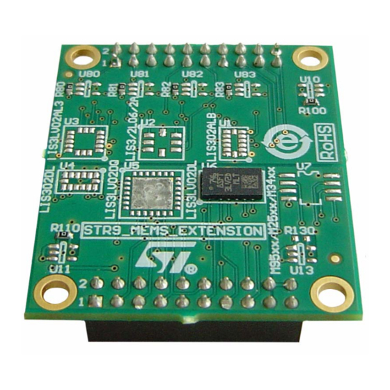
Figure 1.
STR9 MEMS demonstration board
User manual
STEVAL-IFS002V2
STR9 MEMS demonstration board
Rev 3
UM0542
1/20
www.st.com
Advertisement
Table of Contents

Related Manuals for ST STEVAL-IFS002V2


Summary of Contents for ST STEVAL-IFS002V2
-
Page 1: Figure 1. Str9 Mems Demonstration Board
The demonstration board used here can be assembled with several types of digital MEMS sensors as well as analog ones. For data storage, there is assembly space for ST serial Flash. The integration of voltage regulators and operational amplifiers is optional and depends on the intended chip usage. -
Page 2: Table Of Contents
Contents UM0542 Contents Introduction ..........1 STR9 MEMS demonstration board block diagram . - Page 3 UM0542 List of tables List of tables Table 1. Mechanical data (LGA8 package) ..........8 Table 2.
- Page 4 List of figures UM0542 List of figures Figure 1. STR9 MEMS demonstration board ..........1 Figure 2.
-
Page 5: Str9 Mems Demonstration Board Block Diagram
UM0542 STR9 MEMS demonstration board block diagram STR9 MEMS demonstration board block diagram This board is based on STR9 dongle. The main board features are the following: ● Analog MEMS: – LGA8 (LIS2L02AL, LIS2L06AL, LIS3L02AL, LIS3L06AL) – LGA14 (LIS302ALB) – LGA16 (LIS3L02AL3) ●... -
Page 6: Str9 Mems Demonstration Board Schematics
STR9 MEMS demonstration board schematics UM0542 STR9 MEMS demonstration board schematics Figure 3. Schematics - analog and digital MEMS 6/20 Downloaded from Elcodis.com electronic components distributor... -
Page 7: Figure 4. Schematics - I 2 C/Spi Flash/Eeprom Device, Amplifier, Stabilizators
UM0542 STR9 MEMS demonstration board schematics Figure 4. Schematics - I C/SPI Flash/EEPROM device, amplifier, stabilizators 7/20 Downloaded from Elcodis.com electronic components distributor... -
Page 8: Mems Footprints
MEMS footprints UM0542 MEMS footprints LGA8 package Figure 5. MEMS footprint (LGA8 package) Height Width ai14147 Table 1. Mechanical data (LGA8 package) Symbol Dimension Unit 0.79 1.35 1.81 1.81 1.27 Height Width 8/20 Downloaded from Elcodis.com electronic components distributor... -
Page 9: Lga14 Package
UM0542 MEMS footprints LGA14 package Figure 6. MEMS footprint (LGA14 package) Height Width ai14148 Table 2. Mechanical data (LGA14 package) Symbol Dimension Unit 0.64 0.975 Height Width 9/20 Downloaded from Elcodis.com electronic components distributor... -
Page 10: Lga16 (D) Package
MEMS footprints UM0542 LGA16 (D) package Figure 7. MEMS footprint (LGA16 (D) package) Height Width ai14149 Table 3. Mechanical data (LGA16 (D) package) Symbol Dimension Unit 0.65 0.975 3.25 Height Width 10/20 Downloaded from Elcodis.com electronic components distributor... -
Page 11: Lga16 (A) Package
UM0542 MEMS footprints LGA16 (A) package Figure 8. MEMS footprint (LAG16 (A) package) Height Width ai14150 Table 4. Mechanical data (LAG16 (A) package) Symbol Dimension Unit 0.64 0.975 Height Width 11/20 Downloaded from Elcodis.com electronic components distributor... -
Page 12: Qfn28 Package
MEMS footprints UM0542 QFN28 package Figure 9. MEMS footprint (QFN28 package) Height Width ai14151 1. Draft only. Not all the 28 pins are shown. Table 5. Mechanical data (QFN28 package) Symbol Dimension Unit 0.725 3.225 3.225 Height Width 12/20 Downloaded from Elcodis.com electronic components distributor... -
Page 13: Pcb Layout
UM0542 PCB layout PCB layout Figure 10. Top view Figure 11. Bottom view 13/20 Downloaded from Elcodis.com electronic components distributor... -
Page 14: Bill Of Materials And Assembly Instructions
Bill of materials and assembly instructions UM0542 Bill of materials and assembly instructions Table 6 Table 15 show the bill of materials, while sections Section 6.1 Section 6.3 provide additional information on assembly. Assembly information for analog MEMS When U10 LD2980CMxx is not assembled use R100 instead. For low voltage MEMS use a voltage regulator. -
Page 15: Assembly Information For Serial Memory
C Bus EEPROM Table 6. Voltage regulator for analog MEMS Label Comment Footprint Description Assembled Order code LD2980CMxx SOT23-5L Voltage regulator ST: LD2980CMxx ® 0 Ω R100 0603 Resistor : R0603-0R C100 1 µF 0805 Pol. capacitor Farnell: 422-7086 (X7R) C101 2.2 µF... -
Page 16: Analog Mems
Label Comment Footprint Description Assembled Order code ANALOG_CON HDR2X10STD Header 10X2 GM: S2G20 LIS302ALB LGA14AD Analog MEMS ST: LIS302ALB 100 nF 0603 Capacitor Farnell: 422-6859 (X7R) 2.2 µF 1206 Pol. capacitor Farnell: 422-7323 (X7R) ST: LIS3/2L06/2AL LIS3/2L06/2AL LGA8A Analog MEMS... -
Page 17: Table 14. Operational Amplifier Z-Axe For Analog Mems
Bill of materials and assembly instructions Table 11. Memory Label Comment Footprint Description Assembled Order code M95xx/M25xx/ Serial ST: M95xx/M25xx/M34xx Flash/EEPROM M34xx 10 nF 0603 Capacitor Farnell: 422-6859 (X7R) 10 nF 0603 Capacitor Farnell: 422-6938 (X7R) 1. By default, the memory is not assembled. -
Page 18: Table 15. Operational Amplifier Xyz-Axes For Analog Mems
Bill of materials and assembly instructions UM0542 Table 15. Operational amplifier XYZ-axes for analog MEMS Label Comment Footprint Description Assembled Order code Operational TS507ILT SOT23-5L ST: TS507ILT amplifier Ω 0603 Resistor GM: R0603-0R Ω 10 k 0603 Resistor GM: R0603-10k Ω 10 k... -
Page 19: Revision History
UM0542 Revision history Revision history Table 16. Document revision history Date Revision Changes 21-Apr-2008 Initial release. Updated Figure Figure Figure 3 and added Figure 4 17-Oct-2008 (reformatted previous Figure 3 into Figure 3 Figure updated (reformatted) Table 6 Table Renamed “extension board” to demonstration board”, updated 05-Mar-2009 Section 2, renamed title of... - Page 20 No license, express or implied, by estoppel or otherwise, to any intellectual property rights is granted under this document. If any part of this document refers to any third party products or services it shall not be deemed a license grant by ST for the use of such third party products or services, or any intellectual property contained therein or considered as a warranty covering the use in any manner whatsoever of such third party products or services or any intellectual property contained therein.
Need help?
Do you have a question about the STEVAL-IFS002V2 and is the answer not in the manual?
Questions and answers