Table of Contents
Advertisement
Quick Links
UM2681
User manual
Getting started with the wireless power evaluation board for Qi inductive receiver
with STWLC68JRH
Introduction
The
STEVAL-ISB68RX
is an evaluation board based providing a Qi-compliant (Qi specifications 1.2.4) reference solution for a
wireless power receiver with 5 W capability and based on the
STWLC68JRH
chip.
The STEVAL-ISB68RX consists of a PCB housing the STWLC68JRH and a 40 x 40 mm receiving coil: the two elements are
mechanically mated through a plastic frame that also acts as 1.5 mm plastic spacer for the coil. The PCB board also embeds a
2
USB-to-I
C converter that directly interfaces with the STWLC68JRH, allowing the user to modify parameters and settings via a
2
Graphical User Interface (GUI). The converter can be conveniently used to configure and control the final application via I
C
bus.
The STEVAL-ISB68RX has a default setting for a 5 V output voltage and full compliance with Baseline Power Profile (BPP).
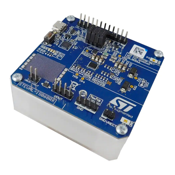
Figure 1.
STEVAL-ISB68RX
UM2681 - Rev 1 - February 2020
www.st.com
For further information contact your local STMicroelectronics sales office.
Advertisement
Table of Contents

Related Manuals for ST STEVAL-ISB68RX


Summary of Contents for ST STEVAL-ISB68RX
-
Page 1: Figure 1. Steval-Isb68Rx
The STEVAL-ISB68RX consists of a PCB housing the STWLC68JRH and a 40 x 40 mm receiving coil: the two elements are mechanically mated through a plastic frame that also acts as 1.5 mm plastic spacer for the coil. The PCB board also embeds a... -
Page 2: Board Overview
UM2681 Board overview Board overview The STEVAL-ISB68RX evaluation board default configuration is optimized for performance. The board features: • STWLC68JRH wireless power receiver chip with up to 5 W output power capability (Qi specification 1.2.4, BPP) • Constant 5 V output voltage (default setting) •... -
Page 3: Board Configuration And Test Points
UM2681 Board configuration and test points Board configuration and test points The STEVAL-ISB68RX has several connectors and test points to ease access to key signals. • P1 connector: micro-USB female receptacle for connection of the USB-to-I C converter to the host PC •... -
Page 4: Operating Mode
STWLC68JRH to the USB-to- C converter, then a USB cable can be plugged into P1 to connect the STEVAL-ISB68RX to the host PC. Before launching the GUI on the host PC, the STEVAL-ISB68RX should be placed on an active transmitter, so that the STWLC68JRH is properly powered and the I C communication established. -
Page 5: Figure 4. Output And Indication Led
Operating mode Figure 4. Output and indication LED The STEVAL-ISB68RX has three additional LEDs dedicated to the USB-to-I C converter: D8 LED indicates the correct initialization, D6 LED indicates I C bus activity and D5 LED is the power-on indicator (USB supply rail). -
Page 6: Default Configuration Of Stwlc68Jrh
The configuration settings of the STWLC68JRH chip are retrieved from the OTP memory at power-up, but they can be temporary changed via GUI once the STEVAL-ISB68RX is powered by the transmitter and the modified values are kept until a reset of chip occurs. -
Page 7: Graphical User Interface (Gui)
USB-to-I2C converter, to rely on for eventually tuning the final application. Figure 6 shows how to change the output voltage of the STEVAL-ISB68RX on-the-fly from the registers page. By acting on the slider (or directly writing the desired value) and writing the related register, a new value is set. -
Page 8: Figure 7. Plotting Key Parameters Via Gui
UM2681 Graphical User Interface (GUI) Figure 7. Plotting key parameters via GUI UM2681 - Rev 1 page 8/18... -
Page 9: Baseline Power Profile (Bpp) Rx Mode Performance
Baseline power profile (BPP) RX mode performance Baseline power profile (BPP) RX mode performance Figure 8 reports the typical TX-input to RX-output efficiency of the STEVAL-ISB68RX placed on open-loop transmitter. Figure 8. STEVAL-ISB68RX evaluation board performance: efficiency vs output power in BPP... -
Page 10: Schematic
UM2681 Schematic Schematic Figure 9. Schematic of STEVAL-ISB68RX Coil Protections Decoupling caps Connectors COIL COIL PGND RSTB VRECT VOUT V5V0 10uF 10uF 10uF 100nF INTB Header 4 VRECT GPIO4 GPIO3 VOUT AGND GPIO2 GPIO1 CPAR GPIO0 3.9nF 100nF 100nF 100nF... -
Page 11: Bom
UM2681 Table 1. Bill of material Item Q.ty Ref. Value Description Manufacturer Part number C1, C4, C6, C7, Multilayer CO4, Ceramic CR4, 100nF, 1005[0402], 50 VDC V, Capacitors Murata GCM155R71H104KE02D CS1, 10%, MLCC - CS2, SMD/SMT CS3, CO1, Multilayer CO2, Ceramic CO3, 10uF, 2012[0805], 35 VDC V, 10%,... - Page 12 UM2681 Item Q.ty Ref. Value Description Manufacturer Part number Q_SMD_LED_0603_DIN1608M, 2 RED LED Wurth Electronik 150060RS55040 VDC V, 20 m A, Q_SMD_LED_0603_DIN1608M, 2 GREEN LED Wurth Electronik 150060VS55040 VDC V, 20 m A, Q_SMD_LED_0603_DIN1608M, 2 YELLOW LED Wurth Electronik 150060YS55040 VDC V, 20 m A, 100pF, 1005[0402], Capacitor...
- Page 13 UM2681 Item Q.ty Ref. Value Description Manufacturer Part number 100R, 1005[0402], Resistor 100K, 1005[0402], Resistor 1M, 1005[0402], Resistor SWITCH_P-DT2112C, 12 VDC V, Tactile Switche P-DT2112C 50 mA, Wireless WLC68_72BUMPS, STMicroelectronics STWLC68 charging IC USB Interface QFN16, Microchip MCP2221A-I/ML SOT23-6L, STMicroelectronics USBLC6-2SC6 Suppressors PowerFLAT, VDS 60 VDC V, Id 7 MOSFET...
-
Page 14: Revision History
UM2681 Revision history Table 2. Document revision history Date Version Changes 20-Feb-2020 Initial release. UM2681 - Rev 1 page 14/18... -
Page 15: Table Of Contents
UM2681 Contents Contents Board overview ..............2 Board configuration and test points. -
Page 16: List Of Tables
UM2681 List of tables List of tables Table 1. Bill of material ..............11 Table 2. -
Page 17: List Of Figures
Plotting key parameters via GUI ............8 Figure 8. STEVAL-ISB68RX evaluation board performance: efficiency vs output power in BPP....9 Figure 9. - Page 18 ST’s terms and conditions of sale in place at the time of order acknowledgement. Purchasers are solely responsible for the choice, selection, and use of ST products and ST assumes no liability for application assistance or the design of Purchasers’...
Need help?
Do you have a question about the STEVAL-ISB68RX and is the answer not in the manual?
Questions and answers