Advertisement
Table of Contents
- 1 Contents
- 2 Cable Preparation and Screen Earthing
- 3 Water Sealing
- 4 Installation of the Cable Reducer
- 5 Tightening of the Contact
- 6 Connector Installation on the Cable
- 7 Connector Installation on the Bushing
- 8 Installation Hint
- 9 Important Notes
- 10 Cable Preparation and Cable Screen Earthing
- Download this manual
IS97082-ENG - 200LR/G-MT345
15 January 2018 - Revision 0
CAUTION : Read instructions thoroughly and completely prior to beginning installation.
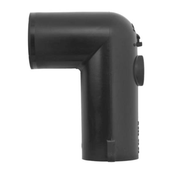
Installation Instructions Separable Elbow Connector - CENELEC interface type A
• For indoor and outdoor applications.
• Only for cables NF C 33-226, UTE C 33-223, NF C 33-223 & HN 33-S-23 [Part 1],
NF C 33-220 (HN 33-S-22) with graphite coating screen [Part 2],
NF C 33-220 (HN 33-S-22) with extruded semi-conductive screen [Part 3].
• In case the ambient temperature is less then 0°C, it could be necessary to warm up the
sealing mastic and tape.
Check if the diameter over cable core insulation is in accordance with
Cable reducer size
(see marking inside cable reducer)
200CA-12
200CA-16
- Supersedes edition of 3 June 2016
(K)200LR
the cable reducer range as indicated in table below:
This product should be installed only by competent personnel trained in good safety practices involving
high voltage electrical equipment. These instructions are not intended as a substitute for adequate
training or experience in such safety practices. These instructions do not attempt to provide for every
possible contingency. Failure to follow these instructions could result in damage to the product and
serious or fatal injury. IMPORTANT : Cable and associated apparatus must be de-energised, locked
out, and tagged prior to product installation.
Up to 24 kV
Dia. over core insulation (mm)
min
13.0
17.5
Page 1/9
max
21.0
25.0
Advertisement
Table of Contents

Related Manuals for Nexans Euromold K200LR


Summary of Contents for Nexans Euromold K200LR
- Page 1 IS97082-ENG - 200LR/G-MT345 15 January 2018 - Revision 0 - Supersedes edition of 3 June 2016 Page 1/9 CAUTION : Read instructions thoroughly and completely prior to beginning installation. Installation Instructions Separable Elbow Connector - CENELEC interface type A (K)200LR Up to 24 kV •...
- Page 2 Page 2/9 Contents : Conductor contact Cable reducer Elbow Roll adhesive 200LRF + Bail restraint 200CA connector housing tape 200LRMC + hex 200LRBA 200LR/G Silicone grease Water sealing Installation Gloves + wipers mastic, type MWS instructions 6 x Stainless steel 3 x Semi- 3 x Earthing straps...
- Page 3 Page 3/9 Part 1. Cable NF C 33-226, UTE C 33-223, NF C 33-223 & HN 33-S-23 For the preparation of the NF C 33-226 cables, please refer to the corresponding instructions marked on the cable : POPY, NIKOL or VINYL. CABLE PREPARATION AND SCREEN EARTHING outer sheath semi-conductive screen...
- Page 4 Page 4/9 WATERSEALING outer water sealing cable mastic sheath adhesive tape solder block water sealing on the braid mastic solder block on the braid 1 Fold one strip of mastic twice (4 layers) and place it under the solder block on the braid. Then wrap the second strip of mastic over the solder block of the braid and around the outer sheath.
- Page 5 Page 5/9 TIGHTENING OF THE CONTACT 10 mm * Only for hex SW 70 - 95 mm² 5 mm 1 Install the contact with the contact palm facing the bushing interface. 2 Tighten the contact until the bolt head shears off. (*) For 70 - 95 mm², tighten again until the second level of the bolt head shears off.
- Page 6 Page 6/9 CONNECTOR INSTALLATION ON THE CABLE clean thoroughly cable reducer lubricate 1 Thoroughly clean cable reducer and contact. 2 Lubricate* the cable reducer and inside surface of the connector. 3 Slide the connector housing on to the reducer until it cannot advance any further. pin contact hex key 4 Insert the supplied hex key into the pin contact.
- Page 7 Page 7/9 CONNECTOR INSTALLATION ON THE BUSHING 1 Clean and lubricate* lightly both é bushing interface and elbow connector & lubricate interface. 2 Place the elbow connector firmly down on the bushing &. 3 Insert bail into the bushing tabs and equipment position bail over elbow connector é.
- Page 8 Page 8/9 Part 2. Cable with graphite coating screen NF C 33-220 (HN 33-S-22) CABLE PREPARATION AND CABLE SCREEN EARTHING copper adhesive outer graphited core insulation sheath tape screen tape interface type A 1 Cut the cable 5 mm from the centerline of the bushing. 2 Remove the outer sheath for a distance of 130 mm.
- Page 9 Remove the core insulation from the conductor for a distance of 30 mm. z Slightly round-off the edge of the core insulation. Do not sharpen in cone-shape. Continue the installation on page 4. Nexans Network Solutions NV - div. EUROMOLD Zuid III - Industrielaan 12 B-9320 EREMBODEGEM-AALST – BELGIUM Tel: +32 (0)53/85 02 11 www.euromold.be - sales.euromold@nexans.com...
Need help?
Do you have a question about the Euromold K200LR and is the answer not in the manual?
Questions and answers