Advertisement
Quick Links
IS97179-ENG - K480TB/G-CW45-CA0
30 October 2019 - Revision 3
CAUTION : Read instructions thoroughly and completely prior to beginning installation.
Installation instructions for separable tee connector - type C interface
Only to be used on copper wire screened cable with extruded semi-conductive screen
Check if the diameter over cable core insulation is in accordance with
Cable reducer size
(see label on cable reducer)
Required components for the connector installation :
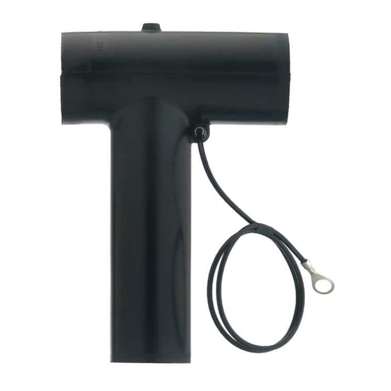
3 x Tee connector
housing - 480BT
3 x Basic
insulating plug +
cap - 800BIPR
Water sealing
mastic, type MWS
(optional)
- Supersedes edition of
28 September 2018
(K)480TB/G
and conductors of copper or aluminium.
the cable reducer range as indicated in table below:
CA0-11
CA0-15
CA0-18
CA0-21
CA0-27
3 x Cable reducer
CA0-W
or
3 x Basic
insulating plug +
cap - 800BIPA
Gloves
This product should be installed only by competent personnel trained in good safety practices involving
high voltage electrical equipment. These instructions are not intended as a substitute for adequate
training or experience in such safety practices. These instructions do not attempt to provide for every
possible contingency. Failure to follow these instructions could result in damage to the product and
serious or fatal injury. IMPORTANT : Cable and associated apparatus must be de-energised, locked
out, and tagged prior to product installation.
Up to 24 kV
Dia. over core insulation (mm)
min
12.0
16.0
19.0
22.0
28.5
3 x Conductor
contact - TBC-X
3 x Clamping
or TMBC-X
screw
+
Silicone grease
1 x Nylon vent rod
+ wipers
Installation
instructions
max
19.0
26.5
32.6
34.6
37.5
or
1 x Installation rod
(for conductor sizes
185 up to 300 mm²)
Roll adhesive
tape
Page 1 of 10
Advertisement

Related Manuals for Nexans Euromold K480TB/G


Summary of Contents for Nexans Euromold K480TB/G
- Page 1 IS97179-ENG - K480TB/G-CW45-CA0 30 October 2019 - Revision 3 - Supersedes edition of 28 September 2018 Page 1 of 10 CAUTION : Read instructions thoroughly and completely prior to beginning installation. Installation instructions for separable tee connector - type C interface (K)480TB/G Up to 24 kV Only to be used on copper wire screened cable with extruded semi-conductive screen...
- Page 2 Page 2 of 10 EQUIPMENT HERE equipment bushing (type C interface ) edge of the outer sheath For outdoor cut back point of outer sheath applications : one layer of water sealing mastic (type MWS) outer cable tape sheath marker copper wires 1 Train the cable into the approximate finished...
-
Page 3: Cable Preparation
Page 3 of 10 CABLE PREPARATION semi-conductive screen core insulation 1 Check distance of 200 mm. 2 Remove the semi-conductive screen to a point 30 mm from the outer sheath. For extruded easy strip semi-conductive screen: Cut squarely taking care not to cut the core insulation. For bonded extruded semi-conductive screen: Use an appropriate pencilling tool. - Page 4 Page 4 of 10 INSTALLATION OF THE CABLE REDUCER For conductor sizes 16 up to 150 mm² core insulation cable reducer lubricate remove protective cable reducer tape marker adhesive tape 1 Lubricate* the indicated area: core insulation, semi-conductive screen, water sealing mastic and inner surface of the reducer.
- Page 5 Page 5 of 10 For conductor sizes 185 mm² up to 300 mm² core installation insulation 1 Slide the installation rod on to the conductor until it butts against the core insulation. lubricate lubricate core insulation installation cable reducer remove protective tape marker adhesive tape...
- Page 6 Page 6 of 10 CRIMPING/TIGHTENING OF THE CONTACT Compression type contacts (Type TBC-X) Please refer to the crimp chart supplied with the contact. deep indent crimping DIN crimping contact palm conductor contact equipment bushing 1 For aluminium conductors : before installing the conductor contact, wire brush the conductor. 2 Fit the contact on to the conductor.
- Page 7 Page 7 of 10 Mechanical type contacts (Type TMBC-X) Before tightening conductor contact contact palm holding tool cable reducer equipment bushing 1 For aluminium conductors : before installing the conductor contact, wire brush the conductor. 2 Insert, if necessary, the centre ring into the contact barrel according to the table in the contact installation instruction.
- Page 8 Page 8 of 10 CONNECTOR INSTALLATION ON CABLE connector clean housing lubricate locking ridge 1 Clean cable reducer, core insulation and contact. 2 Lubricate* the inside of the connector housing and outer surface of the cable reducer. 3 Check if the longer interface of the tee connector is pointed towards the bushing.
- Page 9 Page 9 of 10 50 Nm clamping L ≥ 90 mm screw extension 22 mm socket 1/2" - 12,7 mm torque wrench 3 Insert clamping screw into the threaded hole of the bushing by hand. 4 Use a torque wrench with a 22 mm socket and tighten exerting 50 Nm (5 kgm or 36,9 foot-pounds) of torque. In order to achieve the correct applied torque ensure that there is no lubricant on the threaded parts.
- Page 10 - Do not allow hydrocarbon oils or solvents to contaminate the E.P.D.M. rubber. In the event of contamination, wipe the surface clean with a dry cloth. Nexans Network Solutions NV - div. EUROMOLD Zuid III - Industrielaan 12 B-9320 EREMBODEGEM-AALST – BELGIUM Tel: +32 (0)53/85 02 11 –...
Need help?
Do you have a question about the Euromold K480TB/G and is the answer not in the manual?
Questions and answers