Nexans XPLORER Series Instructions Manual
1u - 12 to 72of patching (sc and lc)
Hide thumbs
Also See for XPLORER Series:
- Instructions manual (30 pages) ,
- Instructions manual (29 pages)
Table of Contents
Advertisement
Quick Links
NOTICE / INSTRUCTIONS
Document : ABS1543/A
Date :
22/05/2019
XPLORER™ 1U - 12 À 72FO BRASSAGE (SC ET LC)
XPLORER™ 1U - 12 TO 72OF PATCHING (SC AND LC)
Tous les schémas, dessins, spécifications, plans et détails de poids, tailles et dimensions figurant dans la
documentation technique ou commerciale de Nexans ont un caractère purement indicatif et ne sauraient
engager Nexans ou être traités comme constitutifs d'une garantie de la part de Nexans.
All drawings, designs, specifications, plans and particulars of weights, size and dimensions contained in the
technical or commercial documentation of Nexans is indicative only and shall not be binding on Nexans or be
treated as constituting a representation on the part of Nexans.
Advertisement
Table of Contents

Related Manuals for Nexans XPLORER Series


Summary of Contents for Nexans XPLORER Series
- Page 1 All drawings, designs, specifications, plans and particulars of weights, size and dimensions contained in the technical or commercial documentation of Nexans is indicative only and shall not be binding on Nexans or be treated as constituting a representation on the part of Nexans.
-
Page 2: Table Of Contents
XPLORER™ Table des matières Table Of Contents DESCRIPTION OVERVIEW .......................4 1.1. PRÉSENTATION DU PRODUIT PRODUCT PRESENTATION ..................4 1.2. CARACTÉRISTIQUES TECHNIQUES TECHNICAL CHARACTERISTICS ................. 5 1.3. KITS FOURNIS PROVIDED KITS ......................6 FIXATION DU PLATEAU FIXATION OF THE MODULE ................7 2.1. - Page 3 XPLORER™ 7.2. FIXATION AVEC ÉCROUS CAGES SUR MONTANTS 19’’ CAGE NUTS FIXATION ON 19’’ FRAMES ..............18 7.3. FIXATION DU KIT DE GUIDAGE ROUTING KIT FIXATION ..................19 INSTRUCTION DE FIN DE VIE END LIFE INSTRUCTION .................21 TRAÇABILITÉ TRACEABILITY ....................21 ABS1543/A 3/21...
-
Page 4: Description Overview
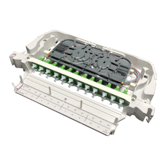
XPLORER™ DESCRIPTION OVERVIEW 1.1. Présentation du produit Product presentation Capot de protection Protective cover Dispositif de fixation pour épanouisseur Fan-out holder Équerre de fixation (dormant) Fixing bracket (fixed chassis) Panneau frontal de brassage 12-72 FO Front patch panel 12-72 OF Loquet Lock Plaque de verrouillage 19’’... -
Page 5: Caractéristiques Techniques Technical Characteristics
XPLORER™ 1.2. Caractéristiques techniques Technical characteristics – Poids : 1,4kg – Weight: 1.4kg – Hauteur : – Height: – Largeur : Standard 19”/ETSI – Width: 19”/ETSI standard – Profondeur : 185mm – Depth: 185mm ETSI 19’’ ABS1543/A 5/21... -
Page 6: Kits Fournis Provided Kits
XPLORER™ 1.3. Kits fournis Provided kits Qté / Description Kit de fixation 19’’ standard Standard 19’’ fixation kit (£↕9,5mm) : (£↕9.5mm): – Douilles – Sockets – Pions – Pawns – Plaque de verrouillage 19’’ 1U – Locking plate 19’’ 1U Kit de fixation 19’’... -
Page 7: Fixation Du Plateau Fixation Of The Module
XPLORER™ FIXATION DU PLATEAU FIXATION OF THE MODULE 2.1. Conditionnement Packaging Battant Swiveling chassis Accessoires Accessories Loquet si non installé Lock if not installed Dormant Fixed chassis Étape optionnelle : Optional step: Mise en place du loquet côté Installing the lock to the opposite of opposé... -
Page 8: Mise En Place Du Dormant Installing The Fixed Chassis
XPLORER™ 2.2. Mise en place du dormant Installing the fixed chassis Standard 19’’ Si l’armoire n’est pas conforme au Standard standard 19’’ £↕9,5mm, se reporter au chapitre 7 (annexes). Dimension carrés 8,3mm Squares dimension If the cabinet is not compliant with the 19’’... -
Page 9: Mise En Place De La Plaque De Verrouillage Installing The Locking Plate
XPLORER™ Sens de la douille et du pion sur le montant arrière. Position of the socket and the pawn in the back frame. Montant arrière Back frame Mise en place des pions (b). Installing pawns (b). Montant arrière Montant avant gauche Back frame Left front frame 2.3. -
Page 10: Mise En Place Du Battant Installing The Swiveling Chassis
XPLORER™ 2.4. Mise en place du battant Installing the swiveling chassis 90° Angle de montage repéré par un index moulé Mounting angle marked by molded index 90° Ne pas déclipper le battant après Do not unclip the swiveling la mise en place. chassis after the installation. -
Page 11: Raccordement Connection
XPLORER™ Refermer le battant S’assurer du bon verrouillage Close the swiveling chassis Ensure to correct locking RACCORDEMENT CONNECTION 3.1. Accès au plateau Opening the module Ouvrir le battant Déclipper le capot Open the swiveling chassis Unclip the cover ABS1543/A 11/21... -
Page 12: Fixation Et Lovage D'un Câble Préconnectorisé Preterminated Cable Fixation And Coiling
XPLORER™ 3.2. Fixation et lovage d’un câble préconnectorisé Preterminated cable fixation and coiling Dispositif de fixation pour épanouisseur Fan-out holder Cas 1 : fixation du câble préconnectorisé dans le battant Case 1: fixation of the preterminated cable in the fixed chassis Câble préconnectorisé... - Page 13 XPLORER™ Cas 2 : fixation du câble préconnectorisé dans le plateau Case 2: fixation of the preterminated cable in the module Câble preterminated Breakout cable Dispositif de fixation pour épanouisseur Fan-out holder Branches Outputs Le raccordement par des cordons The connection by patchcords can de brassage peut s’effectuer selon be carried out according to a similar un principe similaire.
-
Page 14: Fermeture Du Battant Closing The Module
XPLORER™ FERMETURE DU BATTANT CLOSING THE MODULE Refermer le battant Clipper le capot swiveling chassis Clip the cover Close the POSE D’UN CORDON INSTALLING PATCHCORD Ouvrir le volet de la goulotte Insérer le cordon dans la goulotte et et connecter la fiche le faire cheminer côté... -
Page 15: Éléments Particuliers De Maintenance Special Procedures For Maintenance
XPLORER™ ÉLÉMENTS PARTICULIERS DE MAINTENANCE SPECIAL PROCEDURES FOR MAINTENANCE 6.1. Remplacement d’un raccord Adapter replacement Ouvrir le battant et déclipper le capot Déconnecter le pigtail et le cordon Open the swiveling chassis and unclip the Disconnect the pigtail and the patchcord cover Faire pression sur le clip avec un tournevis plat pour permettre le... -
Page 16: Principe De Dépose Du Plateau Module Replacement
XPLORER™ 6.2. Principe de dépose du plateau Module replacement Décabler le plateau Unwire the module Vue de dessus Top view Retrait du pion du montant avant gauche Remove pawn from the left front frame Retrait de la douille du montant avant gauche Remove socket from the left front frame Si l’accessibilité... -
Page 17: Annexes Annex
XPLORER™ ANNEXES ANNEX 7.1. Autres kits à approvisionner en supplément Others kits to be ordered separately Qté / Description Kit de fixation 19’’ (£↕9,5mm) : 19’’ fixation kit (£↕9.5mm): – Écrous cages (£↕9,5mm) – Cage nuts (£↕9.5mm) – Vis hexagonales –... -
Page 18: Fixation Avec Écrous Cages Sur Montants 19'' Cage Nuts Fixation On 19'' Frames
XPLORER™ 7.2. Fixation avec écrous cages sur montants 19’’ Cage nuts fixation on 19’’ frames Utiliser les écrous cages £ ↕8,3mm ou Use cage nuts £↕8.3mm or £↕9.5mm if the £↕9,5mm dans le cas où l’utilisation du système utilisation of the pawns-sockets kit cannot be douilles-pions ne fonctionne pas. -
Page 19: Fixation Du Kit De Guidage Routing Kit Fixation
XPLORER™ 7.3. Fixation du kit de guidage Routing kit fixation Utiliser le kit de guidage dans le cas où les Use the routing kit if the cabinets are not armoires ne sont pas pourvues d’anneaux de provided with lateral routing rings. guidage latéraux. - Page 20 XPLORER™ Cas d’une armoire au format ETSI Cas d’une armoire au format 19’’ In the case of an ETSI cabinet In the case of a 19’’ cabinet Montage du kit bobine sans plaque (d + e) Montage du kit bobine sans plaque (e + d/o) Mounting spool kit without plate (d + e) Mounting spool kit without plate (e + d/o) Montant avant droit (p + q + d)
-
Page 21: Instruction De Fin De Vie End Life Instruction
All drawings, designs, specifications, plans and particulars of weights, size and dimensions contained in the technical or commercial documentation of Nexans is indicative only and shall not be binding on Nexans or be treated as constituting a representation on the part of Nexans.
Need help?
Do you have a question about the XPLORER Series and is the answer not in the manual?
Questions and answers