
Related Manuals for ETS-Lindgren BiConiLog 3143B


Summary of Contents for ETS-Lindgren BiConiLog 3143B
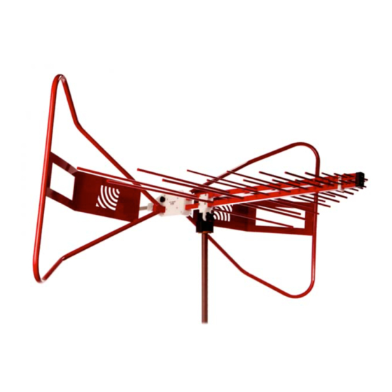
- Page 1 Model 3143B BiConiLog™ Antenna User Manual Model 3143B shown in horizontal polarization...
- Page 2 ETS-Lindgren Inc. reserves the right to make changes to any product described herein in order to improve function, design, or for any other reason. Nothing contained herein shall constitute ETS-Lindgren Inc. assuming any liability whatsoever arising out of the application or use of any product or circuit described herein.
-
Page 3: Table Of Contents
Table of Contents Notes, Cautions, and Warnings ..........v 1.0 Introduction ................7 Tripod Options ....................9 ETS-Lindgren Product Information Bulletin ..........10 2.0 Maintenance ............... 11 Annual Calibration ..................11 Replacement and Optional Parts ..............11 ... - Page 4 This page intentionally left blank.
-
Page 5: Notes, Cautions, And Warnings
Notes, Cautions, and Warnings Note: Denotes helpful information intended to provide tips for better use of the product. Caution: Denotes a hazard. Failure to follow instructions could result in minor personal injury and/or property damage. Included text gives proper procedures. Warning: Denotes a hazard. - Page 6 This page intentionally left blank.
-
Page 7: Introduction
1.0 Introduction The ETS-Lindgren Model 3143B BiConiLog™ Antenna is designed as a dual-purpose antenna that can be used for both immunity and emission testing. From 26 MHz to 6 GHz, the Model 3143B exhibits an average 5.5 dB gain improvement. Applications for the Model 3143B include emissions testing, immunity measurements, and medical... - Page 8 Model 3143B shown in horizontal polarization The Model 3143B includes a stinger mount; it also includes a mounting bracket and 1/4–20 thread knob to attach to an ETS-Lindgren tripod or tower adapter. For the variety of mounting options available for the Model 3143B, see Mounting Instructions on page 19.
-
Page 9: Tripod Options
Tripod Options ETS-Lindgren offers the following non-metallic, non-reflective tripods for use at both indoor and outdoor EMC test sites. For easy horizontal and vertical polarization, the ETS-Lindgren Model 7-TR tripod is recommended. 4-TR Tripod—Constructed of linen phenolic and delrin, designed with an adjustable center post for precise height adjustments. -
Page 10: Ets-Lindgren Product Information Bulletin
ETS-Lindgren Product Information Bulletin See the ETS-Lindgren Product Information Bulletin included with your shipment for the following: Warranty information Safety, regulatory, and other product marking information Steps to receive your shipment Steps to return a component for service ... -
Page 11: Maintenance
2.0 Maintenance Before performing any maintenance, follow the safety information in the ETS-Lindgren Product Information Bulletin included with your shipment. Maintenance of the Model 3143B is WARRANTY limited to external components such as cables or connectors. If you have any questions concerning maintenance, contact ETS-Lindgren Customer Service. -
Page 12: Service Procedures
Service Procedures For the steps to return a system or system component to ETS-Lindgren for service, see the Product Information Bulletin included with your shipment. Maintenance... -
Page 13: Specifications
3.0 Specifications Electrical Specifications Frequency Range: 26 MHz–1 GHz Input Impedance (Nominal): 50 Ω VSWR (Average): 2:1 above 80 MHz Maximum Continuous Power 30 MHz—60 MHz: 500 W 60 MHz—600 MHz: 1 kW 600 MHz—1000 MHz: 500 W Peak Power: 1.3 kW Pattern Type: Directional... - Page 14 This page intentionally left blank. Specifications...
-
Page 15: Assembly Instructions
4.0 Assembly Instructions Before connecting any components, follow the safety information in the ETS-Lindgren Product Information Bulletin included with your shipment. The Model 3143B BiConiLog™ Antenna consists of the following: Antenna Bowtie elements (2) 10–32 thumbscrew knobs to attach bowtie elements (2) ... -
Page 16: Attach Bowtie Elements
Attach Bowtie Elements Photos of bowtie elements used in this section may differ from the bowtie elements for your Model 3143B; the assembly procedure is the same for both. The Model 3143B ships with the bowtie elements detached. To attach the bowtie elements: Assembly Instructions... - Page 17 For stability, mount the Model 3143B onto a tripod or tower. See Mounting Instructions on page 19 for the steps to mount the antenna. Slide the narrow end of one of the bowtie elements into the receptacle hole on the antenna balun, and then align the bowtie with the receptacle on the balun.
- Page 18 This page intentionally left blank. Assembly Instructions...
-
Page 19: Mounting Instructions
5.0 Mounting Instructions Before connecting any components, follow the safety information in the ETS-Lindgren Product Information Bulletin included with your shipment. The Model 3143B antenna is a precision measurement device. Handle with care. Contact with any metal or non-metallic structure can capacitively load the antenna, which may cause unrepeatable results. -
Page 20: Using Included Mounting Adapters
Using Included Mounting Adapters In addition to the attached mounting bracket and mounting knobs, the Model 3143B ships with these mounting adapters: 100989 Polarizing Mounting Adapter with 7/8–14 thread receptacle If you need to convert the polarizing adapter to a 1/4–20 receptacle, insert the 1/4–20 thread insert into the polarizing adapter ... - Page 21 To attach the included adapters to the Model 3143B: Model 3143B mounted onto 4-TR using included 100989 Polarizing Mounting Adapter and 105861 1/4–20 Thread Insert If required, insert the 1/4–20 thread insert into the mounting adapter. Remove the mounting knob from the mounting bracket on the antenna. Slide the mounting bracket onto the mounting adapter with the adapter placed between the shoulders of the mounting bracket.
-
Page 22: Using The Stinger To Mount To A Model 2175 Minimast
Using the Stinger to Mount to a Model 2175 MiniMast Do not use the stinger to mount the Model 3143B onto a 4-TR tripod. ° The stinger mount provides on-axis rotation during 90 horizontal or vertical polarization. The stinger enables you to mount the antenna directly to an ETS-Lindgren 7-TR Tripod or mast. - Page 23 2. Attach the cable to the Type N connector at the end of the stinger. 3. Slide the cable and stinger into the clamp on the boom, carefully guiding the cable out the other end. Mounting Instructions...
- Page 24 4. When you reach the back of the balun box, align it with the boom receptacle, and then slide the smaller portion of the balun box into the boom. This will prevent rotation of the antenna unless the boom is being polarized.
-
Page 25: Additional Mounting Options
Additional Mounting Options 4-TR M OUNTING PTIONS Following are additional options for mounting the Model 3143B onto an ETS-Lindgren 4-TR tripod. Contact the ETS-Lindgren Sales Department for information on ordering optional mounting hardware. Mounting Instructions... -
Page 26: 7-Tr And Mast Mounting Options
7-TR OUNTING PTIONS The stinger on the Model 3143B enables you to mount to antenna directly to an ETS-Lindgren 7-TR Tripod Positioner. However, following are additional options for mounting the Model 3143B onto an ETS-Lindgren 7-TR Tripod Positioner. Contact the ETS-Lindgren Sales Department for information on ordering... - Page 27 Mast refers to 2070 Series, 2075, and 2175 Antenna Towers. 7-TR refers to 109042, 108983, and 108197 booms: 109042 boom—Straight boom; for general antenna mounting on a 7-TR 108983 boom—Offset boom; for general antenna mounting on a 7-TR with pneumatic or manual polarization; can also be used to mount stinger-type antennas ...
-
Page 28: 2X2 Boom Mounting Options
OUNTING PTIONS Following are additional options for mounting the Model 3143B onto a 2x2 boom. Contact the ETS-Lindgren Sales Department for information on ordering optional mounting hardware. 2x2 boom refers to a typical 2-inch by 2-inch boom. Mounting Instructions... -
Page 29: Typical Data
6.0 Typical Data Typical Antenna Factor and Gain Distance for the ANSI 3-meter and 10-meter calibrations is measured from the antenna midpoint, and for SAE 1-meter calibrations the distance is measured from the antenna tip. Midpoint is defined as half the distance between the small elements and the bowties, which is about 45 cm from the small end tip. -
Page 30: Typical Vswr
Typical VSWR Typical Data... -
Page 31: Typical Beamwidth
Typical Beamwidth Typical Data... -
Page 32: Typical Power Requirements
Typical Power Requirements ORIZONTAL Typical Data... -
Page 33: Vertical
ERTICAL Typical Data... -
Page 34: Symmetry
YMMETRY Typical Data... - Page 35 Frequency (MHz) Symmetry (dB) -0.01 -0.06 -0.04 0.02 -0.05 -0.01 0.03 0.05 0.01 0.01 -0.03 0.07 0.02 -0.02 -0.01 0.09 0.02 -0.09 0.21 0.01 0.14 0.05 -0.04 0.19 Typical Data...
- Page 36 Frequency (MHz) Symmetry (dB) 0.03 -0.29 0.18 0.46 0.06 -0.18 -0.22 1000 0.05 Typical Data...
-
Page 37: Appendix A: Warranty
Appendix A: Warranty See the Product Information Bulletin included with your shipment for the complete ETS-Lindgren warranty for your Model 3143B BiConiLog™ Antenna. 3143B URATION OF ARRANTIES FOR ODEL All product warranties, except the warranty of title, and all remedies for warranty failures are limited to two years.
Need help?
Do you have a question about the BiConiLog 3143B and is the answer not in the manual?
Questions and answers