Table of Contents
Advertisement
Quick Links
Advertisement
Table of Contents

Related Manuals for ETS-Lindgren BiConiLog 3142C


Summary of Contents for ETS-Lindgren BiConiLog 3142C
- Page 1 Archived 01/19/11 Model 3142C BiConiLog™ Antenna User Manual...
- Page 2 Although the information in this document has been carefully reviewed and is believed to be reliable, ETS-Lindgren does not assume any liability arising out of the application or use of any product or circuit described herein; nor does it convey any license under its patent rights nor the rights of others.
-
Page 3: Table Of Contents
Archived 01/19/11 Table of Contents Safety Symbol Definitions ......................... v General Safety Considerations ......................v 1.0 Introduction ..........................7 2.0 Receiving Your Order ........................ 9 2.1 Unpacking and Acceptance ....................9 2.2 Return Procedures ......................... 9 3.0 Maintenance ..........................11 4.0 Mounting Instructions ...................... - Page 4 Archived 01/19/11 This page intentionally left blank.
-
Page 5: Safety Symbol Definitions
Definition BEFORE SERVICING: CONTACT ETS-LINDGREN (+1.512.531.6400)—Servicing or modifying the unit without ETS-Lindgren authorization may void your warranty. If an attempt to WARRANTY service the unit must be made, disconnect all electrical power prior to beginning. Voltages exist at many points within the instrument that could, if contacted, cause personal injury. - Page 6 Archived 01/19/11 This page intentionally left blank.
-
Page 7: Introduction
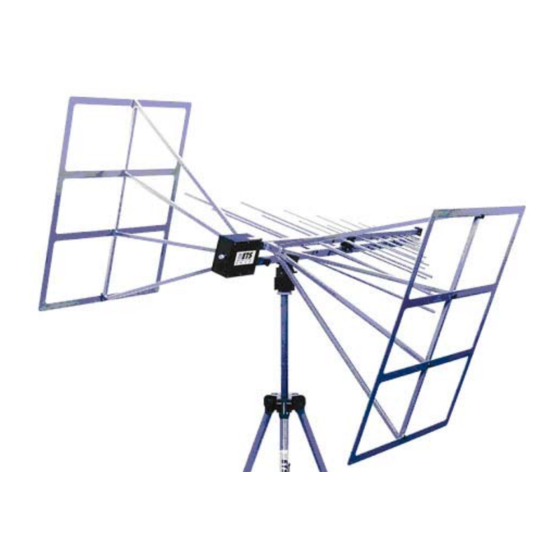
Archived 01/19/11 1.0 Introduction The ETS-Lindgren Model 3142C BiConiLog™ Antenna is designed as a dual- purpose antenna that can be used for both emissions and immunity applications. The Model 3142C is a hybrid linearly polarized EMC antenna consisting of a log-periodic dipole array (LPDA) and a single bow-tie antenna. - Page 8 Archived 01/19/11 With the end plates attached to the Model 3142C bow-tie elements, the equivalent dipole electrical length is increased, which decreases resonant frequency and increases efficiency in the 20 to 60 MHz range. Similarly, the regular bow-tie has a lower resonant frequency than an equal length single-wire dipole.
-
Page 9: Receiving Your Order
Include the serial number of the item being returned. Step 3. Package the system or component carefully. If possible, use the original packing materials to return a system or system component to ETS-Lindgren at the following address: ETS-Lindgren Attn. - Page 10 Archived 01/19/11 This page intentionally left blank. Receiving Your Order...
-
Page 11: Maintenance
3.0 Maintenance To ensure reliable and repeatable long-term performance, annual recalibration of your antenna by ETS-Lindgren’s experienced technicians is recommended. Our staff can recalibrate almost any type or brand of antenna. Please call to receive a Service Order Number prior to sending an antenna to us for calibration. - Page 12 Archived 01/19/11 This page intentionally left blank. Maintenance...
-
Page 13: Mounting Instructions
Archived 01/19/11 4.0 Mounting Instructions 4.1 Model 3142C Components The Model 3142C BiConiLog™ Antenna consists of the following: • (1) Antenna • (2) Bow-tie elements • (2) 10-32 thread knobs to attach bow-tie elements • (2) Protective end caps for bow-tie elements •... -
Page 14: Connect The Optional End Plates To Create The T Bow-Ties
Archived 01/19/11 3. Insert one of the 10-32 thread knobs into the opposite side of the boom from where you inserted the bow-tie. Slowly tighten the knob, taking care not to cross-thread the connection. Cross-threading the connection could cause permanent damage to the bow-tie element. 4. - Page 15 T end frames can be removed when mounting vertically on a standard tripod. A special tripod is available from ETS-Lindgren for vertical polarization with T bow-ties intact. Please contact ETS-Lindgren for the recommended mounting scheme.
- Page 16 Archived 01/19/11 This page intentionally left blank. Mounting Instructions...
-
Page 17: Application
E-field squared, or: P(E V/m) = E P(1 V/m) Actual transmitted field strength should be verified using an ETS-Lindgren electric field probe, or an equivalent. A n estimate of the power required, taking... -
Page 18: With Optional End Plates
V / m V / m Actual transmitted field strength should be verified using an ETS-Lindgren electric field probe, or an equivalent. For IEC 1000-4-3 type testing, the antenna tip can be placed at any distance between one and three meters from the EUT as long as the front face plane is illuminated according to the –0,+6 dB specification. -
Page 19: Typical Data Without Optional End Plates
Archived 01/19/11 6.0 Typical Data Without Optional End Plates 6.1 Model 3142C Typical 26-3000 MHz VSWR 1000 3000 Frequency (MHZ) 6.2 Model 3142C Typical 26-3000 MHz Antenna Factor Distance for the ANSI 3 and 10 meter calibrations is measured from the antenna midpoint, and for SAE 1 meter calibrations the distance is measured from the antenna tip. -
Page 20: Model 3142C Typical 26-3000 Mhz Gain
Archived 01/19/11 6.3 Model 3142C Typical 26-3000 MHz Gain This data is derived from the 3 antenna method antenna factors. 1000 3000 Frequency (M z) Typical Data Without Optional End Plates... -
Page 21: Typical Data With Optional End Plates
Archived 01/19/11 7.0 Typical Data with Optional End Plates The power shown was measured over a ground plane with 1.5 meters transmit antenna and probe height, horizontal polarization. Horizontal polarization is the worst-case power required; typically less power is required for vertical polarization. -
Page 22: Model 3142C Typical 26-3000 Mhz Antenna Factor
Archived 01/19/11 7.2 Model 3142C Typical 26-3000 MHz Antenna Factor Distance for the ANSI 3 meter and 10 meter calibrations is measured from the antenna midpoint, and for SAE 1 meter calibrations the distance is measured from the antenna tip. Midpoint is defined as half the distance between the small elements and the bow-ties, which is about 45 cm from the small end tip. -
Page 23: Model 3142C Typical 26-3000 Mhz 1M Forward Power
Archived 01/19/11 7.3 Model 3142C Typical 26-3000 MHz 1M Forward Power The following illustrates the typical 26-3000 MHz forward power required for 1, 3, and 10 V/m at 1 meter from the tip of the antenna. 1000 1 V/m 80% AM 3 V/m 80% AM 10 V/m... -
Page 24: Model 3142C Typical 26-3000 Mhz 3M Forward Power
Archived 01/19/11 7.4 Model 3142C Typical 26-3000 MHz 3M Forward Power The following illustrates the typical 26-3000 MHz forward power required for 1, 3, and 10 V/m at 3 meters from the antenna tip. 1 V/m 80% AM 1000 3 V/m 80% AM 10 V/m 80% AM... -
Page 25: Specifications
Archived 01/19/11 8.0 Specifications 8.1 Electrical Specifications With Standard Bow-tie With Optional End Plates Elements 26-3000 MHz 26-3000 MHz Frequency Range: 50 Ω 50 Ω Input Impedance 2:1 average 2:1 average VSWR: 26 MHz – 60 MHz500 W60 26 MHz – 60 MHz500 W60 MHz –... - Page 26 Archived 01/19/11 This page intentionally left blank. Specifications...
-
Page 27: Warranty Policy For Standard Emco Brand Products
Archived 01/19/11 9.0 Warranty Policy for Standard EMCO Brand Products 9.1 Scope and Duration of Warranties Seller warrants to Buyer that the Standard EMCO Brand Products Excluding 5211 & 5220 be (1) free from defects in material, manufacturing workmanship, and title, and (2) conform to the Seller’s applicable product descriptions and specifications, if any, contained in or attached to Seller’s quotation. -
Page 28: Buyer's Remedies
Archived 01/19/11 OTHERWISE, WHETHER OF MERCHANTABILITY OR FITNESS FOR ANY PARTICULAR PURPOSE OR USE OR OTHERWISE ON THE PRODUCTS, OR ON ANY PARTS OR LABOR FURNISHED DURING THE SALE, DELIVERY OR SERVICING OF THE PRODUCTS. THERE ARE NO WARRANTIES WHICH EXTEND BEYOND THE DESCRIPTION ON THE FACE HEREOF. - Page 29 Archived 01/19/11 The remedies set forth herein are conditioned upon Buyer promptly notifying Seller within the applicable warranty period of any defect or nonconformance and making the product available for correction. The preceding paragraphs set forth Buyer’s exclusive remedies and Seller’s sole liability for claims based on failure of the products to meet any warranty, whether the claim is in contract, warranty, tort (including negligence and strict liability) or otherwise, and however instituted, and, upon the expiration of the applicable...
Need help?
Do you have a question about the BiConiLog 3142C and is the answer not in the manual?
Questions and answers