
Related Manuals for ETS-Lindgren BiConiLog 3140B


Summary of Contents for ETS-Lindgren BiConiLog 3140B
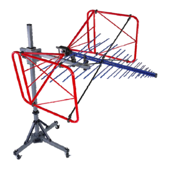
- Page 1 Model 3140B BiConiLog™ Antenna User Manual Model 3140B mounted onto a 7-TR tripod (not included)
- Page 2 ETS-Lindgren L.P. reserves the right to make changes to any product described herein in order to improve function, design, or for any other reason. Nothing contained herein shall constitute ETS-Lindgren L.P. assuming any liability whatsoever arising out of the application or use of any product or circuit described herein.
-
Page 3: Table Of Contents
Using Included Adapters to Mount to an Offset Boom ......... 24 Attach Included Mounting Adapters to Model 3140B ......24 Attach Model 3140B to an ETS-Lindgren Offset Boom ....... 25 Mounting Illustrations ................... 26 Model 3140B on 7-TR Tripod Positioner ..........26 ... - Page 4 7.0 Typical Data ................ 33 Model 3140B Typical VSWR ............... 33 Model 3140B Typical Antenna Factors ............34 Model 3140B Gain ..................35 Model 3140B Typical Forward Power (FP) ..........36 Typical 1 Meter FP Based on 1 Meter Antenna Factor ....... 37 ...
-
Page 5: Notes, Cautions, And Warnings
Included text gives proper procedures. Warning: Denotes a hazard. Failure to follow instructions could result in SEVERE personal injury and/or property damage. Included text gives proper procedures. See the ETS-Lindgren Product Information Bulletin for safety, regulatory, and other product marking information. - Page 6 This page intentionally left blank.
-
Page 7: Introduction
1.0 Introduction The ETS-Lindgren Model 3140B BiConiLog is a high-field antenna in the bow tie/log periodic family, providing the highest field-to-power ratio at low frequencies of any of the BiConiLog antennas. The Model 3140B is designed specifically to generate the field... - Page 8 The unique feature of the Model 3140B is the T bow tie elements. A T bow tie increases the equivalent dipole electrical length, thereby decreasing resonant frequency and increasing efficiency in the 20 MHz to 60 MHz range. Similarly, a regular bow tie has a lower resonant frequency than an equal length single-wire dipole.
-
Page 9: About Mounting The Model 3140B
Mounting Instructions on page 23. 7-TR T RIPOD OSITIONER ETS-Lindgren offers the non-metallic, non-reflective Model 7-TR for use at both indoor and outdoor EMC test sites. Constructed of PVC and fiberglass components, providing increased stability for physically large antennas. The unique design allows for quick assembly, disassembly, and convenient storage. -
Page 10: Ets-Lindgren Product Information Bulletin
ETS-Lindgren Product Information Bulletin See the ETS-Lindgren Product Information Bulletin included with your shipment for the following: • Warranty information • Safety, regulatory, and other product marking information • Steps to receive your shipment • Steps to return a component for service •... -
Page 11: Maintenance
See the Product Information Bulletin included with your shipment for information on ETS-Lindgren calibration services. Service Procedures For the steps to return a system or system component to ETS-Lindgren for service, see the Product Information Bulletin included with your shipment. Maintenance... - Page 12 This page intentionally left blank. Maintenance...
-
Page 13: Specifications
3.0 Specifications Electrical Specifications Frequency Range: 26 MHz–3000 MHz 50 Ω Input Impedance: VSWR (Average): CW Power (Average): • 26 MHz to 150 MHz = 750 W • 150 MHz to 600 MHz = 500 W • 600 MHz to 1 GHz = 365 W •... - Page 14 This page intentionally left blank. Specifications...
-
Page 15: Assembly Instructions
4.0 Assembly Instructions Before connecting any components, follow the safety information in the ETS-Lindgren Product Information Bulletin included with your shipment. Model 3140B Components The Model 3140B BiConiLog™ Antenna consists of the following: • Antenna • Bow tie elements (2) •... -
Page 16: Model 3140B Assembled
Model 3140B Assembled Assembly Instructions... -
Page 17: Steps To Assemble The Model 3140B
Steps to Assemble the Model 3140B To eliminate stress and prevent damage to the balun box connection, you must support the antenna while attaching the bow tie elements. TTACH LEMENTS Place the bow tie vertically on the floor and hold the antenna horizontally. - Page 18 Assembly Instructions...
-
Page 19: Attacht Leg Elements
TTACH LEMENTS Insert one long T leg element into the clamp and tighten the clamp screws. See illustration on next page. Repeat for second T leg element. Assembly Instructions... - Page 20 Assembly Instructions...
-
Page 21: Attach Diagonal Struts
TTACH IAGONAL TRUTS Attach the four diagonal struts. • Loosen the thumbscrew at each strut mount on the T leg element and at the boom. • Place the pocket of the straight end facing the raised face of each mount. •... -
Page 22: Attachv Elements
TTACH LEMENTS Attach the V elements and tighten the thumbscrews through the boom The Model 3140B is now ready for mounting to a tripod or mast. See Mounting Instructions on page 23. Assembly Instructions... -
Page 23: Mounting Instructions
Product Information Bulletin included with your shipment. The Model 3140B is a precision measurement device. Handle with care. Do not mount the Model 3140B onto an ETS-Lindgren 4-TR Tripod. Included Mounting Adapters The Model 3140B BiConiLog™ ships with these mounting adapters: • 100989 Polarizing Mounting Adapter with 7/8–14 thread... -
Page 24: Using Included Adapters To Mount To An Offset Boom
Using Included Adapters to Mount to an Offset Boom 3140B TTACH NCLUDED OUNTING DAPTERS TO ODEL To allow manual polarization of the Model 3140B, install the 100989 polarizing adapters with the curve at the top of each adapter facing the same direction. -
Page 25: Attach Model 3140B To An Ets-Lindgren Offset Boom
3140B ETS-L TTACH ODEL TO AN INDGREN FFSET Place the Model 3140B onto the offset boom with the attached polarizing adapters flat against the top surface of the boom. Holding the Model 3140B securely, insert one 105861B 1/4–20 thread insert into the underside of the offset boom. Attach the two mount knobs and tighten to secure the Model 3140B to the offset boom. -
Page 26: Mounting Illustrations
Mounting Illustrations 3140B 7-TR T ODEL RIPOD OSITIONER Mounting Instructions... -
Page 27: Model 3140B On Model 2075 Minimast
3140B 2075 M ODEL ODEL Mounting Instructions... -
Page 28: Model 3140B On Model 2070/2071 Antenna Positioning Mast
3140B 2070/2071 A ODEL ODEL NTENNA OSITIONING Mounting Instructions... -
Page 29: Additional Mounting Options
7-TR OUNTING PTIONS Following are options for mounting the Model 3140B onto an ETS-Lindgren 7-TR Tripod or mast. Contact the ETS-Lindgren Sales Department for information on ordering optional mounting hardware. Mast refers to 2070 Series, 2075, and 2175 Antenna Towers. -
Page 30: 2X2 Boom Mounting Options
OUNTING PTIONS Following are options for mounting the Model 3140B onto a 2x2 boom. Contact the ETS-Lindgren Sales Department for information on ordering optional mounting hardware. 2x2 boom refers to a typical 2-inch by 2-inch boom Mounting Instructions... -
Page 31: Application
Model 3140B before dropping vertically. Both horizontal and vertical polarizations are easily accomplished when the Model 3140B is mounted on an ETS-Lindgren tower. The Model 7-TR Tripod Positioner is designed specifically for T bow tie BiConiLog antennas for easy changes to polarization, and with the air polarization option can provide automated polarization using a Model 2090 Multi-Device Controller. - Page 32 3.24 (1.8 ). Actual transmitted field strength should be verified using an ETS-Lindgren Model HI-6005 Field Probe, or equivalent. The forward power data graphs on page 39 and page 40 show power requirements for the lower frequencies at three meters based on measurements using a field probe on an Open Area Test Site (OATS) over both conducting ground and a (2.4m)
-
Page 33: Typical Data
7.0 Typical Data Model 3140B Typical VSWR This graph illustrates the typical VSWR for Model 3140B in the frequency range 26 MHz to 3000 MHz. Typical Data... -
Page 34: Model 3140B Typical Antenna Factors
Model 3140B Typical Antenna Factors This graph illustrates the typical horizontal antenna factors for the Model 3140B in the frequency range 26 MHz to 3000 MHz. The separation distance for the ANSI C63.5 three and 10 meter calibrations is measured from the antenna midpoint, while for SAE/ARP-958 one meter calibrations the distance is measured from the antenna tip. -
Page 35: Model 3140B Gain
Model 3140B Gain This graph illustrates one and three meter gain. Typical Data... -
Page 36: Model 3140B Typical Forward Power (Fp)
Model 3140B Typical Forward Power (FP) The forward power graphs illustrate the typical forward power required for one, three, and 10 V/m (with and without 80% amplitude modulation). • The graph on page 37 illustrates one meter from the tip of the antenna, and the graph on page 38 illustrates three meters from the tip of the antenna. -
Page 37: Typical 1 Meter Fp Based On 1 Meter Antenna Factor
FP B YPICAL ETER ASED ON ETER NTENNA ACTOR Typical Data... -
Page 38: Typical 3 Meter Fp Based On 3 Meter Antenna Factor
FP B YPICAL ETER ASED ON ETER NTENNA ACTOR Typical Data... -
Page 39: Typical 3 Meter Fp Over Ferrite Tile
FP O YPICAL ETER ERRITE Typical Data... -
Page 40: Typical 3 Meter Fp Measured Over Conducting Ground
FP M YPICAL ETER EASURED ONDUCTING ROUND Typical Data... -
Page 41: Appendix A: Warranty
Appendix A: Warranty See the Product Information Bulletin included with your shipment for the complete ETS-Lindgren warranty for your Model 3140B. 3140B URATION OF ARRANTIES FOR ODEL All product warranties, except the warranty of title, and all remedies for warranty failures are limited to two years.
Need help?
Do you have a question about the BiConiLog 3140B and is the answer not in the manual?
Questions and answers