Table of Contents
Advertisement
Quick Links
Advertisement
Table of Contents

Subscribe to Our Youtube Channel
Related Manuals for ETS-Lindgren BiConiLog 3149


Summary of Contents for ETS-Lindgren BiConiLog 3149
- Page 1 Model 3149 BiConiLog™ Antenna User Manual...
- Page 2 ETS-Lindgren L.P. reserves the right to make changes to any product described herein in order to improve function, design, or for any other reason. Nothing contained herein shall constitute ETS-Lindgren L.P. assuming any liability whatsoever arising out of the application or use of any product or circuit described herein.
-
Page 3: Table Of Contents
1.0 Introduction ................7 Standard Configuration .................. 8 Tripod Options ....................9 ETS-Lindgren Product Information Bulletin ..........10 2.0 Maintenance ............... 11 Annual Calibration ..................11 Replacement and Optional Parts ..............11 ... - Page 4 This page intentionally left blank.
-
Page 5: Notes, Cautions, And Warnings
Included text gives proper procedures. Warning: Denotes a hazard. Failure to follow instructions could result in SEVERE personal injury and/or property damage. Included text gives proper procedures. See the ETS-Lindgren Product Information Bulletin for safety, regulatory, and other product marking information. - Page 6 This page intentionally left blank.
-
Page 7: Introduction
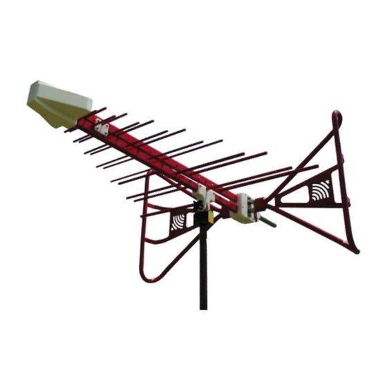
1.0 Introduction The ETS-Lindgren Model 3149 BiConiLog™ is a dual-purpose antenna that can be used for both emissions and immunity applications. The Model 3149 is a hybrid linearly polarized EMC antenna consisting of a log periodic dipole array (LPDA) and a single bow tie antenna. -
Page 8: Standard Configuration
• The lower element boom mount on the Model 3149 can be used with all tripods and with ETS-Lindgren antenna masts that have an offset cross boom. For the steps to mount the Model 3149, see Mounting Instructions on page 17. -
Page 9: Tripod Options
Tripod Options ETS-Lindgren offers the following non-metallic, non-reflective tripods for use at both indoor and outdoor EMC test sites. • 4-TR Tripod—Constructed of linen phenolic and delrin, designed with an adjustable center post for precise height adjustments. Maximum height is 2.0 m (80.0 in), and minimum height is 94 cm... -
Page 10: Ets-Lindgren Product Information Bulletin
ETS-Lindgren Product Information Bulletin See the ETS-Lindgren Product Information Bulletin included with your shipment for the following: • Warranty information • Safety, regulatory, and other product marking information • Steps to receive your shipment • Steps to return a component for service •... -
Page 11: Maintenance
Thread Insert 105861B For additional/optional mounting hardware, see Additional Mounting Options on page 19. Service Procedures For the steps to return a system or system component to ETS-Lindgren for service, see the Product Information Bulletin included with your shipment. Maintenance... - Page 12 This page intentionally left blank. Maintenance...
-
Page 13: Specifications
3.0 Specifications Electrical Specifications 80 MHz–5 GHz Frequency Range: 50 Ω Impedance (Nominal): 6.5:1 (maximum) VSWR (Average): <2:1 (typical) Maximum Continuous Power: • 800 W: 80 MHz–150 MHz • 500 W: 150 MHz–600 MHz • 360 W: 600 MHz–1 GHz •... - Page 14 This page intentionally left blank. Specifications...
-
Page 15: Bow Tie Assembly Instructions
4.0 Bow Tie Assembly Instructions Before connecting any components, follow the safety information in the ETS-Lindgren Product Information Bulletin included with your shipment. The Model 3149 ships with the bow tie elements detached. The tubular bow tie elements easily attach to the balun box using positive aligning compression fittings. - Page 16 Do not cross thread this connection or permanent damage to the bow tie element could occur. Thread the compression fittings together using the included wrench. Repeat steps 2 and 3 for the second bow tie element. Bow Tie Assembly Instructions...
-
Page 17: Mounting Instructions
5.0 Mounting Instructions Before connecting any components, follow the safety information in the ETS-Lindgren Product Information Bulletin included with your shipment. The Model 3149 is a precision measurement device. Handle with care. Using Included Mounting Adapters The Model 3149 BiConiLog™ Antenna ships with these mounting adapters: •... - Page 18 1. Located on the bottom of the polarizing adapter is a 7/8–14 thread receptacle; if you need to convert to a 1/4–20 receptacle, insert the 1/4–20 thread insert into the polarizing adapter. 2. Attach the polarizing adapter to tripod or tower.
-
Page 19: Using The Stinger Mount
Additional hardware is required to use the stinger to mount the Model 3149 to a mast. For information on ordering optional mounting hardware, contact the ETS-Lindgren Sales Department. Do not use the stinger to mount the Model 3149 onto a 4-TR tripod. -
Page 20: Additional Mounting Options
Additional Mounting Options 4-TR M OUNTING PTIONS Following are additional options for mounting the Model 3149 onto an ETS-Lindgren 4-TR tripod. Contact the ETS-Lindgren Sales Department for information on ordering optional mounting hardware. Mounting Instructions... -
Page 21: 7-Tr And Mast Mounting Options
The stinger on the Model 3149 enables you to mount to antenna directly to an ETS-Lindgren 7-TR Tripod Positioner. Following are additional options for mounting the Model 3149 onto an ETS-Lindgren 7-TR Tripod Positioner. Contact the ETS-Lindgren Sales Department for information on ordering optional mounting hardware. -
Page 22: 2X2 Boom Mounting Options
OUNTING PTIONS Following are additional options for mounting the Model 3149 onto a 2x2 boom. Contact the ETS-Lindgren Sales Department for information on ordering optional mounting hardware. 2x2 boom refers to a typical 2-inch by 2-inch boom. Mounting Instructions... -
Page 23: Other Mounting Options
THER OUNTING PTIONS Following are additional options for using the stinger to mount the Model 3149 onto a non-stinger mount. Contact the ETS-Lindgren Sales Department for information on ordering optional mounting hardware. Mounting Instructions... - Page 24 This page intentionally left blank. Mounting Instructions...
-
Page 25: Application
E-field squared, or: P(E V/m) = E P(1 V/m) Actual transmitted field strength should be verified using an ETS-Lindgren electric field probe, or equivalent. For IEC 1000-4-3 type testing, the antenna tip can be placed at any distance between one and three meters from the EUT as long as the front face plane is illuminated according to the -0, +6 dB uniform field specification. - Page 26 This page intentionally left blank. Application...
-
Page 27: Typical Data
7.0 Typical Data Model 3149 Antenna Factor at 10m Typical Data... -
Page 28: Model 3149 Gain At 10M
Model 3149 Gain at 10m Typical Data... -
Page 29: Model 3149 Forward Power
Model 3149 Forward Power Typical Data... -
Page 30: Model 3149 Horizontal Measured Power
Model 3149 Horizontal Measured Power Power requirements scaled from measured data for 3 V/m at 80% modulation over ferrite up to 1 GHz and measured over EHP-18PCL from 1 GHz to 2 GHz (horizontal polarization). Reference point: 3 m from antenna tip and 1.2 m over ground. -
Page 31: Model 3149 Vertical Measured Power
Model 3149 Vertical Measured Power Power requirements scaled from measured data for 3 V/m at 80% modulation over ferrite up to 1 GHz and measured over EHP-18PCL from 1 GHz to 2 GHz (vertical polarization). Reference point: 3 m from antenna tip and 1.2 m over ground. - Page 32 This page intentionally left blank. Typical Data...
-
Page 33: Appendix A: Warranty
Appendix A: Warranty See the Product Information Bulletin included with your shipment for the complete ETS-Lindgren warranty for your Model 3149. 3149 URATION OF ARRANTIES FOR ODEL All product warranties, except the warranty of title, and all remedies for warranty failures are limited to two years.
Need help?
Do you have a question about the BiConiLog 3149 and is the answer not in the manual?
Questions and answers