
Subscribe to Our Youtube Channel
Related Manuals for ETS-Lindgren 3112


Summary of Contents for ETS-Lindgren 3112
- Page 1 ® Advanced Test Equipment Rentals www.atecorp.com 800-404-ATEC (2832) Models 3112, 3106B, 3119, 3115, 3117, 3116C Double-Ridged Waveguide Horn Antennas User Manual...
- Page 2 ETS-Lindgren L.P. reserves the right to make changes to any products herein to improve functioning or design. Although the information in this document has been carefully reviewed and is believed to be reliable, ETS-Lindgren does not assume any liability arising out of the application or use of any product or circuit described herein;...
-
Page 3: Table Of Contents
Electrical Specifications ....................13 Physical Specifications ..................... 15 4.0 Mounting Instructions ................17 Model 3112 Optional Positioning System ................. 17 4-TR Mounting Instructions ....................21 7-TR Mounting Instructions ....................23 5.0 Typical Data ....................27 ... -
Page 4: Notes, Cautions, And Warnings
Notes, Cautions, and Warnings Note: Denotes helpful information intended to provide tips for better use of the product. Caution: Denotes a hazard. Failure to follow instructions could result in minor personal injury and/or property damage. Included text gives proper procedures. Warning: Denotes a hazard. -
Page 5: Introduction
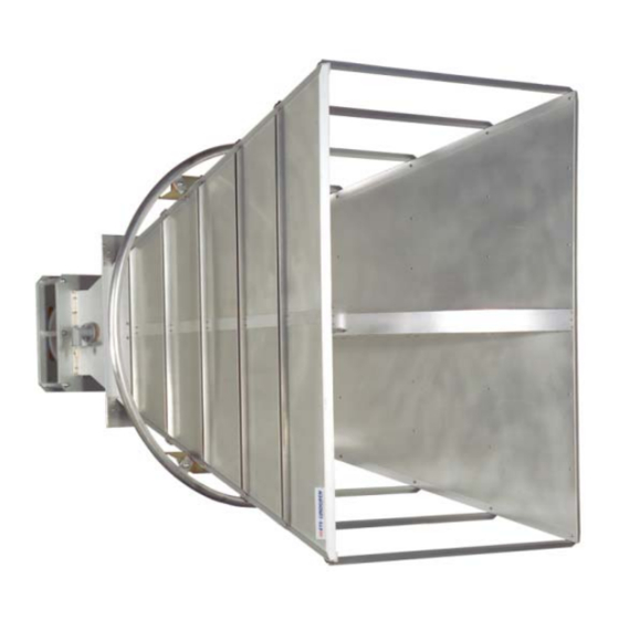
Horn Antenna is a linearly polarized antenna covering the frequency range of 100 MHz to 1 GHz. The Model 3112 is especially effective for generating high electromagnetic fields with relatively low power input. The antenna is also useful for receiving low-level signals where high gain characteristics are needed. - Page 6 3119 ODEL The Model 3119 Double-Ridged Waveguide Horn Antenna is a linearly polarized broadband antenna covering the frequency range of 400 MHz to 6 GHz. The Model 3119 is ideally suited for immunity over 1 GHz and as a reference antenna for wireless testing.
-
Page 7: Optional Items
3116C ODEL The Model 3 3116C Double e-Ridged Wav veguide Horn Antenn na is a linearly y polarized broadband a antenna cove ring the frequ uency range 10 GH Hz to 40 GHz . It is designe ed and built specific cally for emiss sions and susceptibility... - Page 8 7-TR T ODEL RIPOD The 7-TR R Tripod is con nstructed of P PVC and fiberglass s components s, providing in ncreased stability fo or physically l large antenna as. The uniqu design al lows for quick k assembly, d disassembly and conv venient storag...
- Page 9 3112 P ODEL OSITIONING YSTEM The Model 3112 features an option for a fixed height pneumatic assisted polarization positioning system. The position system is ideal when using the Model 31112 for immunity testing. 160 mA 120 VAC Power Supply Optional 220 VAC available...
-
Page 10: Ets-Lindgren Product Information Bulletin
See the ETS-Lindgren Product Information Bulletin included with your shipment for the following: Warranty information Safety, regulatory, and other product marking information Steps to receive your shipment Steps to return a component for service ETS Lindgren calibration service ETS Lindgren contact information Introduction... -
Page 11: Maintenance
2.0 Mainte enance Before perf forming any maintenanc e, follow the e safety information n in the ETS- -Lindgren Pr roduct Inform mation Bulletin inc cluded with y your shipme Maintenanc ce of a Doub ble-Ridged W Waveguide An ntenna is RRANTY limited to e external com... -
Page 12: Service Procedures
Service Procedures For the steps to return a system or system component to ETS-Lindgren for service, see the Product Information Bulletin included with your shipment. Maintenance... -
Page 13: Specifications
3.0 Specifications Electrical Specifications 3112 ODEL Frequency Range 100 MHz—1 GHz VSWR Ratio (Average) < 1.6:1 Maximum Continuous Power 800 W 1.5 kW (Type N, female connector) Peak Power 2.5 kW CW (EIA 1 ⅝ in. flange connector) 50 Ω... - Page 14 3119 ODEL Frequency Range 400 MHz—6 GHz VSWR Ratio (Average) 3.5:1 Maximum Continuous Power 800 W Peak Power 2500 W 50 Ω Impedance (Nominal) Connector Type N, female Front-to-Back Ratio 20 dB 20 dB minimum Cross Polarization 3115 ODEL Frequency Range 750 MHz—18 GHz VSWR Ratio (Average) Maximum Continuous Power...
-
Page 15: Physical Specifications
Impedance (Nominal) Type K, female Connector 2.92 mm Front-to-Back Ratio 20 dB Cross Polarization 20 dB minimum Physical Specifications 3112 ODEL Width 203.2 cm (80 in) Depth 182 cm (71.65 in) Height 139.7 cm (56 in) 86.1 kg (189.81 lbs) - Page 16 3115 ODEL Width 24.4 cm (9.6 in) Depth 27.9 cm (11 in) Height 15.9 cm (6.2 in) Approximate Weight 1.8 kg (4 lbs) 3117 ODEL Width 17.5 cm (6.9 in) 17.5 cm + 15.5 cm mount Depth (6.9 in + 6.1 in mount) Height 15.5 cm (6.1 in) Approximate Weight...
-
Page 17: Mounting Instructions
The customer is responsible for providing an adequate and safe support system for the Model 3112 Double Ridged Waveguide Horn Antenna when moving and attaching to the optional positioning system. - Page 18 The Model 3112 Double Ridged Waveguide Horn antenna includes a series of outer holes in the rear plate that is compatible with the optional positioning system. Additionally, the mounting holes can be used to meet customer specific mounting requirements. Mounting Instructions...
- Page 19 ONNECTING THE PTIONAL OSITIONING YSTEM Once the Model 3112 is securely mounted on the positioner, loosen the nuts and turn the wheel at the base of the horn support for better field uniformity. This bore sights the horn 10 degrees. 3112...
- Page 20 IR POLARIZATION PTION Plug the ends of the twin air hoses into the two AIR OUT connectors located on the interface box at the base of the custom positioning system. Plug the opposite ends of the twin hoses into the two 90 degree fittings on the air cylinder of the custom positioning system.
-
Page 21: 4-Tr Mounting Instructions
4-TR Mou nting Instruc ctions to the size o of the Model 3 3112, 3119 a and 3106B Do ouble-Ridged Wave eguide Horn Antennas, d do not moun nt them onto a 4-TR tripo Failu ure to provide e continuous... - Page 22 TINGE OUNT TACHMENT stinger moun t is included w with the Mode el 3117 anten nna for center rline rotation easurements . When using the Model 31 117 with the 4 4-TR the mou unting bracket ust be attache 1. Hold th he antenna wi th the connec ctor pointing t...
-
Page 23: 7-Tr Mounting Instructions
Please refer to the Model 7-TR manual for mounting instructions and options. Following are options for mounting a Double-Ridged Waveguide Antenna (except the Model 3112) onto an ETS-Lindgren 7-TR Tripod or mast. Contact the ETS- Lindgren Sales Department for information on ordering optional mounting hardware. - Page 24 7-TR T RIPOD PTIONS 109042 boom—Straight boom; for general antenna mounting on a 7-TR 108983 boom—offset boom; for general antenna mounting on a 7-TR with pneumatic or manual polarization; can also be used to mount stinger-type antennas 108507 boom—Centerline rotation boom for Model 3106 Series antennas only; when changing polarization, maintains centerline rotation Mounting Instructions...
- Page 25 PTIONS 2x2 boom refers to a typical 2-inch by 2-inch boom. Following are additional options for mounting the Double-Ridged Waveguide Antenna onto a 2x2 boom. Contact the ETS Lindgren Sales Department for information on ordering optional mounting hardware. Mounting Instructions...
- Page 26 7-TR P OUNT NTENNA TO OSITIONER Please review the mounting instructions included in the Model 7-TR manual. 7-TR shown with Model 3106B mounted onto 7-TR with optional 108507 centerline rotation boom Mounting Instructions...
-
Page 27: Typical Data
5.0 Typical Data Before placing into operation, follow the safety information in the ETS-Lindgren Product Information Bulletin included with your shipment. Model 3112 Typical Data... - Page 28 Typical Data...
-
Page 29: Model 3106B
Model 3106B Typical Data... - Page 30 Typical Data...
-
Page 31: Model 3119
Model 3119 Typical Data... - Page 32 Typical Data...
- Page 33 Typical Data...
-
Page 34: Model 3115
Model 3115 Typical Data... - Page 35 Typical Data...
- Page 36 Typical Data...
-
Page 37: Model 3117
Model 3117 Typical Data... - Page 38 Typical Data...
- Page 39 Typical Data...
-
Page 40: Model 3116C
Model 3116C Typical Data... - Page 41 Typical Data...
- Page 42 Typical Data...
-
Page 43: Appendix A: Warranty
AVEGUIDE NTENNAS All product warranties, except the warranty of title, and all remedies for warranty failures are limited to two year. Product Warranted Duration of Warranty Period Model 3112 2 Years Model 3106B 2 Years Model 3119 2 Years Model 3115... - Page 44 This page intentionally left blank. Warranty...
-
Page 45: Appendix B: Typical Measured Radiated Patterns
Appendix B: Typical Measured Radiated Patterns 3106B ODEL Typical Measured Radiated Patterns... - Page 46 Typical Measured Radiated Patterns...
- Page 47 Typical Measured Radiated Patterns...
- Page 48 Typical Measured Radiated Patterns...
- Page 49 Typical Measured Radiated Patterns...
- Page 50 3119 ODEL Typical Measured Radiated Patterns...
- Page 51 Typical Measured Radiated Patterns...
- Page 52 Typical Measured Radiated Patterns...
- Page 53 Typical Measured Radiated Patterns...
- Page 54 Typical Measured Radiated Patterns...
- Page 55 Typical Measured Radiated Patterns...
- Page 56 3115 ODEL Typical Measured Radiated Patterns...
- Page 57 Typical Measured Radiated Patterns...
- Page 58 Typical Measured Radiated Patterns...
- Page 59 Typical Measured Radiated Patterns...
- Page 60 Typical Measured Radiated Patterns...
- Page 61 Typical Measured Radiated Patterns...
- Page 62 3117 ODEL Typical Measured Radiated Patterns...
- Page 63 Typical Measured Radiated Patterns...
- Page 64 Typical Measured Radiated Patterns...
- Page 65 Typical Measured Radiated Patterns...
- Page 66 Typical Measured Radiated Patterns...
- Page 67 Typical Measured Radiated Patterns...
- Page 68 Typical Measured Radiated Patterns...
- Page 69 Typical Measured Radiated Patterns...
- Page 70 Typical Measured Radiated Patterns...
- Page 71 Typical Measured Radiated Patterns...
- Page 72 Typical Measured Radiated Patterns...
- Page 73 Typical Measured Radiated Patterns...
- Page 74 This page intentionally left blank. Typical Measured Radiated Patterns...
Need help?
Do you have a question about the 3112 and is the answer not in the manual?
Questions and answers