
Subscribe to Our Youtube Channel
Related Manuals for ETS-Lindgren 3181


Summary of Contents for ETS-Lindgren 3181
- Page 1 Model 3181 / Model 3183 / Model 3184 End Fed Mini-Bicon Antenna User Manual Model 3181 / Model 3184 Model 3183...
- Page 2 ETS-Lindgren L.P. reserves the right to make changes to any product described herein in order to improve function, design, or for any other reason. Nothing contained herein shall constitute ETS-Lindgren L.P. assuming any liability whatsoever arising out of the application or use of any product or circuit described herein.
-
Page 3: Table Of Contents
7-TR and Mast Mounting Options ............23 2x2 Boom Mounting Options ............... 25 Weatherizing Kit for Outdoor Testing (3181/3184 Only) ......26 Step 1: Wrap Moldable Plastic Seal Tape ........... 27 Step 2: Mold Plastic Seal Tape............28 ... - Page 4 3184 Antenna Factor / Gain..............33 3184 VSWR ..................34 Typical E-Plane Patterns—Model 3181 ............35 3181 E-Plane at 500 MHz—1 GHz ............35 3181 E-Plane at 2 GHz –5 GHz............36 3181 E-Plane at 6 GHz–9 GHz............37 ...
- Page 5 3184 E-Plane at 10 GHz–11 GHz............64 3184 E-Plane at 12 GHz–13 GHz............65 3184 E-Plane at 14 GHz–15 GHz............66 3184 E-Plane at 16 GHz–17 GHz............67 3184 E-Plane at 18 GHz ..............68 ...
- Page 6 This page intentionally left blank.
-
Page 7: Notes, Cautions, And Warnings
Included text gives proper procedures. Warning: Denotes a hazard. Failure to follow instructions could result in SEVERE personal injury and/or property damage. Included text gives proper procedures. See the ETS-Lindgren Product Information Bulletin for safety, regulatory, and other product marking information. - Page 8 This page intentionally left blank. viii |...
-
Page 9: 1.0 Introduction
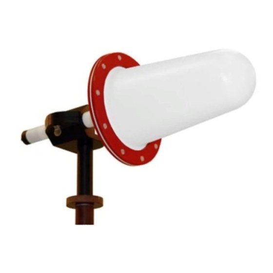
1.0 Introduction The ETS-Lindgren End Fed Mini-Bicons includes these two groups of broadband omni-directional antennas: Model 3181 / Model 3184 The Model 3181/3184 is designed for surveillance, spectrum monitoring, and shielding tests. The frequency range for the Model 3181 is 500 MHz to 9 GHz and the frequency range for the Model 3184 is 1 GHz to 18 GHz. -
Page 10: Tripod Options
Specification Compliance Testing. Typical data is provided starting on page 29. The Model 3181/3183/3184 includes a stinger mount and ships with an antenna mount assembly for a variety of mounting configurations. For information on the 4-TR, see the next section, Tripod Options;... -
Page 11: Ets-Lindgren Product Information Bulletin
ETS-Lindgren Product Information Bulletin See the ETS-Lindgren Product Information Bulletin included with your shipment for the following: • Warranty information • Safety, regulatory, and other product marking information • Steps to receive your shipment • Steps to return a component for service •... - Page 12 This page intentionally left blank. Introduction...
-
Page 13: 2.0 Maintenance
See the Product Information Bulletin included with your shipment for information on ETS-Lindgren calibration services. Replacement and Optional Parts Following are the part numbers for ordering replacement or optional parts for the Model 3181/3183/3184 End Fed Mini--Bicon Antennas. Part Description Part Number Assembly, Antenna Mount... -
Page 14: Service Procedures
Service Procedures For the steps to return a system or system component to ETS-Lindgren for service, see the Product Information Bulletin included with your shipment. Maintenance... -
Page 15: 3.0 Specifications
25 W @ 18 GHz 50 Ω Impedance: SMA female Connector: Physical Specifications Length: • 3181/3184: 38.35 cm (15.1 in) • 3183: 37.3 cm (14.67 in) Width: • 3181/3184: 15.25 cm (6.0 in) • 3183: 7.0 cm (2.76 in) Stinger Length: • 3181/3183/3184: 16.0 cm (6.32 in) - Page 16 This page intentionally left blank. Specifications...
-
Page 17: 4.0 Mounting Instructions
4.0 Mounting Instructions Before connecting any components, follow the safety information in the ETS-Lindgren Product Information Bulletin included with your shipment. The Model 3181/3183/3184 antennas are precision measurement devices. Handle your antenna with care. Mounting Instructions... -
Page 18: Using The Antenna Mount Assembly On A 4-Tr
Each Model 3181/3183/3184 End Fed Mini-Bicon Antenna ships with an antenna mount assembly for a variety of mounting configurations. To use the antenna mount assembly with an ETS-Lindgren 4-TR Tripod, select the antenna mounting orientation, attach the antenna mount assembly to the 4-TR, and then attach the antenna to the antenna mount assembly. -
Page 19: Step 1: Attach Antenna Mount Assembly To 4-Tr
1: A 4-TR TTACH NTENNA OUNT SSEMBLY TO You may use the antenna mount assembly to mount the Model 3181/3183/3184 in vertical or horizontal orientation. • Vertical orientation: Attach the extension to the threaded insert on the bottom of the mount and rotate to tighten into place. - Page 20 To direct mount, attach the mount to the 4-TR using the threaded insert on the side of the mount. Rotate to tighten into place. To use the extension, attach the extension to the mount using the threaded insert on the side of the mount, and then turn the extension to tighten. Attach the extension to the 4-TR using the threaded insert on the bottom of the extension.
-
Page 21: Step 2: Mount Antenna To Antenna Mount Assembly
2: M OUNT NTENNA TO NTENNA OUNT SSEMBLY • Turn the thumbscrew/knob to loosen it. • Insert the antenna stinger into and through the clamping aperture. • Turn the thumbscrew/knob to tighten it and secure the antenna in place. Vertical Mount Horizontal Mount Mounting Instructions... -
Page 22: Step 3: Orient To Notch (Model 3183 Only)
3: O 3183 O RIENT TO OTCH ODEL • For consistency and reduced uncertainty, use the notch on the antenna shaft to orient the Model 3183. This ensures that the same part of the Model 3183 will face the receive antenna during the sVSWR test. -
Page 23: Additional Mounting Options
Following are options for mounting the Model 3181/3183/3184 onto an ETS-Lindgren 7-TR Tripod or mast. See Using the Antenna Mount Assembly on a 4-TR on page 18 for additional mounting and assembly information. Contact the ETS-Lindgren Sales Department for information on ordering optional mounting hardware. - Page 24 Mast refers to 2070 Series, 2075, and 2175 Antenna Towers. 7-TR refers to 109042, 106328, and 108197 booms: • 109042 boom—Straight boom; for general antenna mounting on a 7-TR • 106328 boom—Offset boom; for general antenna mounting on a 7-TR with pneumatic or manual polarization •...
-
Page 25: 2X2 Boom Mounting Options
OUNTING PTIONS Following are additional options for mounting the Model 3181/3183/3184 onto a 2x2 boom. See Using the Antenna Mount Assembly on a 4-TR on page 18 for additional mounting and assembly information. Contact the ETS-Lindgren Sales Department for information on ordering optional mounting hardware. -
Page 26: Weatherizing Kit For Outdoor Testing (3181/3184 Only)
The larger knob provides the same functionality but provides increased usability. The Model 3181/3184 ships with a weatherizing kit to protect the cable connection during outdoor use. The kit includes moldable plastic seal tape and heavy-duty all-weather vinyl tape. -
Page 27: Step 1: Wrap Moldable Plastic Seal Tape
Follow these steps to apply the tapes: 1: W OLDABLE LASTIC • Make sure the antenna shaft, cable, and connectors are clean and dry. • Attach the antenna cable to the antenna connector. • Start wrapping the plastic seal tape 1.0 inch below the base of the antenna cable connector... -
Page 28: Step 2: Mold Plastic Seal Tape
2: M LASTIC • Press firmly and uniformly over the plastic seal tape to mold it into place. • Squeeze out any trapped air as you press the plastic seal tape. 3: W EAVY EATHER INYL • Start wrapping 1/2 inch below where the plastic seal tape begins and wrap upward to... -
Page 29: 5.0 Typical Data
5.0 Typical Data Model 3181 3181 A NTENNA ACTOR Typical Data... -
Page 30: 3181 Vswr
3181 VSWR Typical Data... -
Page 31: Model 3183
Model 3183 3183 A NTENNA ACTOR Typical Data... -
Page 32: 3183 Vswr
3183 VSWR Typical Data... -
Page 33: Model 3184
Model 3184 3184 A NTENNA ACTOR Typical Data... -
Page 34: 3184 Vswr
3184 VSWR Typical Data... -
Page 35: Typical E-Plane Patterns-Model 3181
Typical E-Plane Patterns—Model 3181 3181 E-P 500 MH —1 GH LANE AT Typical Data... -
Page 36: 3181 E-Plane At 2 Ghz -5 Ghz
3181 E-P 2 GH –5 GH LANE AT Typical Data... -
Page 37: 3181 E-Plane At 6 Ghz-9 Ghz
3181 E-P 6 GH –9 GH LANE AT Typical Data... -
Page 38: 3181 E-Plane At 10 Ghz-13 Ghz
3181 E-P 10 GH –13 GH LANE AT Typical Data... -
Page 39: 3181 E-Plane At 14 Ghz-18 Ghz
3181 E-P 14 GH –18 GH LANE AT Typical Data... -
Page 40: Typical E-Plane Patterns-Model 3183
Typical E-Plane Patterns—Model 3183 3183 E-P 1 GH LANE AT Typical Data... -
Page 41: 3183 E-Plane At 2 Ghz
3183 E-P 2 GH LANE AT Typical Data... -
Page 42: 3183 E-Plane At 3 Ghz
3183 E-P 3 GH LANE AT Typical Data... -
Page 43: 3183 E-Plane At 4 Ghz
3183 E-P 4 GH LANE AT Typical Data... -
Page 44: 3183 E-Plane At 5 Ghz
3183 E-P 5 GH LANE AT Typical Data... -
Page 45: 3183 E-Plane At 6 Ghz
3183 E-P 6 GH LANE AT Typical Data... -
Page 46: 3183 E-Plane At 7 Ghz
3183 E-P 7 GH LANE AT Typical Data... -
Page 47: 3183 E-Plane At 8 Ghz
3183 E-P 8 GH LANE AT Typical Data... -
Page 48: 3183 E-Plane At 9 Ghz
3183 E-P 9 GH LANE AT Typical Data... -
Page 49: 3183 E-Plane At 10 Ghz
3183 E-P 10 GH LANE AT Typical Data... -
Page 50: 3183 E-Plane At 11 Ghz
3183 E-P 11 GH LANE AT Typical Data... -
Page 51: 3183 E-Plane At 12 Ghz
3183 E-P 12 GH LANE AT Typical Data... -
Page 52: 3183 E-Plane At 13 Ghz
3183 E-P 13 GH LANE AT Typical Data... -
Page 53: 3183 E-Plane At 14 Ghz
3183 E-P 14 GH LANE AT Typical Data... -
Page 54: 3183 E-Plane At 15 Ghz
3183 E-P 15 GH LANE AT Typical Data... -
Page 55: 3183 E-Plane At 16 Ghz
3183 E-P 16 GH LANE AT Typical Data... -
Page 56: 3183 E-Plane At 17 Ghz
3183 E-P 17 GH LANE AT Typical Data... -
Page 57: 3183 E-Plane At 18 Ghz
3183 E-P 18 GH LANE AT Typical Data... -
Page 58: Typical H-Plane Patterns-Model 3183
Typical H-Plane Patterns—Model 3183 3183 H-P 1 GH LANE AT Typical Data... -
Page 59: 3183 H-Plane At 2 Ghz-18 Ghz
3183 H-P 2 GH –18 GH LANE AT Typical Data... -
Page 60: Typical E-Plane Patterns-Model 3184
Typical E-Plane Patterns—Model 3184 3184 E-P 2 GH –3 GH LANE AT Typical Data... -
Page 61: 3184 E-Plane At 4 Ghz-5 Ghz
3184 E-P 4 GH –5 GH LANE AT Typical Data... -
Page 62: 3184 E-Plane At 6 Ghz-7 Ghz
3184 E-P 6 GH –7 GH LANE AT Typical Data... -
Page 63: 3184 E-Plane At 8 Ghz-9 Ghz
3184 E-P 8 GH –9 GH LANE AT Typical Data... -
Page 64: 3184 E-Plane At 10 Ghz-11 Ghz
3184 E-P 10 GH –11 GH LANE AT Typical Data... -
Page 65: 3184 E-Plane At 12 Ghz-13 Ghz
3184 E-P 12 GH –13 GH LANE AT Typical Data... -
Page 66: 3184 E-Plane At 14 Ghz-15 Ghz
3184 E-P 14 GH –15 GH LANE AT Typical Data... -
Page 67: 3184 E-Plane At 16 Ghz-17 Ghz
3184 E-P 16 GH –17 GH LANE AT Typical Data... -
Page 68: 3184 E-Plane At 18 Ghz
3184 E-P 18 GH LANE AT Typical Data... -
Page 69: Typical H-Plane Patterns-Model 3184
Typical H-Plane Patterns—Model 3184 3184 H-P 1 GH LANE AT Typical Data... -
Page 70: 3184 H-Plane At 2 Ghz-18 Ghz
3184 H-P 2 GH –18 GH LANE AT Typical Data... -
Page 71: Appendix A: Warranty
Appendix A: Warranty See the Product Information Bulletin included with your shipment for the complete ETS-Lindgren warranty for your Model 3181/3183/3184. 3181/3183/3184 URATION OF ARRANTIES FOR ODEL All product warranties, except the warranty of title, and all remedies for warranty failures are limited to two years.
Need help?
Do you have a question about the 3181 and is the answer not in the manual?
Questions and answers