Table of Contents
Advertisement
Quick Links
Advertisement
Table of Contents

Related Manuals for ETS-Lindgren 3148B


Summary of Contents for ETS-Lindgren 3148B
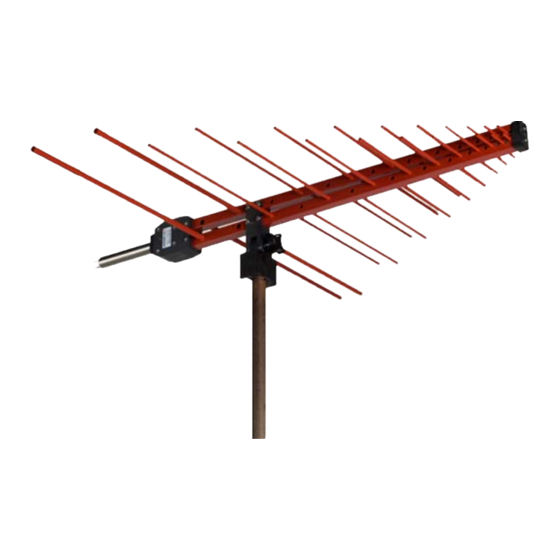
- Page 1 Model 3148B Log Periodic Dipole Array Antenna User Manual...
- Page 2 ETS-Lindgren L.P. reserves the right to make changes to any product described herein in order to improve function, design, or for any other reason. Nothing contained herein shall constitute ETS-Lindgren L.P. assuming any liability whatsoever arising out of the application or use of any product or circuit described herein.
-
Page 3: Table Of Contents
Table of Contents Notes, Cautions, and Warnings ........... v 1.0 Introduction ................7 Tripod Options ....................8 ETS-Lindgren Product Information Bulletin ...........9 2.0 Maintenance ................ 11 Annual Calibration ..................11 Replacement and Optional Parts..............11 Service Procedures ..................12 3.0 Specifications............... 13 Electrical Specifications ................13 Physical Specifications ................13... - Page 4 1100 MHz ....................35 1200 MHz ....................35 1300 MHz ....................36 1400 MHz ....................36 1500 MHz ....................37 1600 MHz ....................37 1700 MHz ....................38 1800 MHz ....................38 1900 MHz ....................39 2000 MHz ....................39 Appendix A: Warranty ..............41...
-
Page 5: Notes, Cautions, And Warnings
Included text gives proper procedures. Warning: Denotes a hazard. Failure to follow instructions could result in SEVERE personal injury and/or property damage. Included text gives proper procedures. See the ETS-Lindgren Product Information Bulletin for safety, regulatory, and other product marking information. - Page 6 This page intentionally left blank.
-
Page 7: Introduction
The Model 93148B is a non-characterized version of the Model 3148B. Should calibration/characterization be desired please contact our calibration department. A variety of mounting options are available for the Model 3148B. For information, see Mounting Instructions on page 15. Introduction... -
Page 8: Tripod Options
Tripod Options ETS-Lindgren offers the following nonmetallic, non-reflective tripods for use at both indoor and outdoor EMC test sites. • Model 4-TR—Constructed of linen phenolic and delrin, designed with an adjustable center post for precise height adjustments. Maximum height is 2.0 m (80.0 in), and minimum height is 94 cm (37.0 in). -
Page 9: Ets-Lindgren Product Information Bulletin
ETS-Lindgren Product Information Bulletin See the ETS-Lindgren Product Information Bulletin included with your shipment for the following: • Warranty information • Safety, regulatory, and other product marking information • Steps to receive your shipment • Steps to return a component for service •... - Page 10 This page intentionally left blank. Introduction...
-
Page 11: Maintenance
Before performing any maintenance, follow the safety information in the ETS-Lindgren Product Information Bulletin included with your shipment. Maintenance of the Model 3148B is limited WARRANTY to external components such as cables or connectors. If you have any questions concerning maintenance, contact ETS-Lindgren Customer Service. -
Page 12: Service Procedures
Thread Insert 105861B For additional/optional mounting hardware, see Additional Mounting Options on page 19. Service Procedures For the steps to return a system or system component to ETS-Lindgren for service, see the Product Information Bulletin included with your shipment. Maintenance... -
Page 13: Specifications
3.0 Specifications Electrical Specifications 200 MHz–2 GHz Frequency Range: Average: 1.2:1 VSWR Ratio: Maximum: 2.0:1 1 kW Maximum Continuous Power: 1.3 kW Peak Power: Ω Impedance: ± 0.5 dB Symmetry: Better than 20 dB below Cross-Polarization Rejection: 1000 MHz Type N female Connector: Physical Specifications 6.667 cm... - Page 14 This page intentionally left blank. Specifications...
-
Page 15: Mounting Instructions
7/8–14 thread receptacle • 105861B 1/4–20 Thread Insert To use these adapters to mount the Model 3148B to a tripod or tower: Located on the bottom of the polarizing adapter is a 7/8–14 thread receptacle; if you need to convert to a 1/4–20 receptacle, insert the 1/4–20 thread insert into the polarizing... - Page 16 Do not cross thread or permanent damage to the adapter and thread insert could occur. Remove the mounting knob from the mounting bracket on the antenna. Slide the mounting bracket onto the polarizing adapter with the polarizing adapter placed between the shoulders of the mounting bracket.
- Page 17 Shown mounted onto a 4-TR Mounting Instructions...
-
Page 18: Using The Stinger Mount
Using the Stinger Mount The stinger on the Model 3148B enables you to mount to antenna directly to an ETS-Lindgren 7-TR Tripod Positioner or mast. Additional hardware is required to use the stinger to mount the Model 3148B to a mast. For information on ordering optional mounting hardware, contact the ETS-Lindgren Sales Department. -
Page 19: Additional Mounting Options
Additional Mounting Options 4-TR M OUNTING PTIONS Following are additional options for mounting the Model 3148B onto an ETS-Lindgren 4-TR tripod. Contact the ETS-Lindgren Sales Department for information on ordering optional mounting hardware. Mounting Instructions... - Page 20 7-TR OUNTING PTIONS The stinger on the Model 3148B enables you to mount to antenna directly to an ETS-Lindgren 7-TR Tripod Positioner. Following are additional options for mounting the Model 3148B onto an ETS-Lindgren 7-TR Tripod Positioner. Contact the ETS-Lindgren Sales Department for information on ordering optional mounting hardware.
- Page 21 OUNTING PTIONS Following are additional options for mounting the Model 3148B onto a 2x2 boom. Contact the ETS-Lindgren Sales Department for information on ordering optional mounting hardware. 2x2 boom refers to a typical 2-inch by 2-inch boom. Mounting Instructions...
- Page 22 This page intentionally left blank. Mounting Instructions...
-
Page 23: Application
5.0 Application Emissions and Immunity The antenna label on the Model 3148B Log Periodic Dipole Array marks the centerline and tip of the antenna, indicating where to perform measurements. Application... -
Page 24: Operation
Where possible, run the feed cable straight at least one meter or more back from the Model 3148B before dropping vertically. - Page 25 For IEC/EN 31000-4-3 type testing, the antenna tip can be placed at any distance between one and three meters from the EUT as long as the front face plane is illuminated according to the -0, +6 dB uniform field specifications. It is usually necessary to place RF absorbing material between the EUT and antenna to suppress ground plane reflection to ensure the field uniformly, or to conduct the immunity test in a fully-lined anechoic room.
- Page 26 This page intentionally left blank. Application...
-
Page 27: Typical Data
6.0 Typical Data Antenna Factor Typical Data... -
Page 28: Gain
Gain Typical Data... -
Page 29: Vswr
VSWR Typical Data... -
Page 30: Half-Power Beamwidth
Half-Power Beamwidth Typical Data... -
Page 31: Typical Radiation Patterns
7.0 Typical Radiation Patterns 400 MHz Typical Radiation Patterns... -
Page 32: 500 Mhz
500 MHz 600 MHz Typical Radiation Patterns... -
Page 33: 700 Mhz
700 MHz 800 MHz Typical Radiation Patterns... -
Page 34: 900 Mhz
900 MHz 1000 MHz Typical Radiation Patterns... -
Page 35: 1100 Mhz
1100 MHz 1200 MHz Typical Radiation Patterns... -
Page 36: 1300 Mhz
1300 MHz 1400 MHz Typical Radiation Patterns... -
Page 37: 1500 Mhz
1500 MHz 1600 MHz Typical Radiation Patterns... -
Page 38: 1700 Mhz
1700 MHz 1800 MHz Typical Radiation Patterns... -
Page 39: 1900 Mhz
1900 MHz 2000 MHz Typical Radiation Patterns... - Page 40 This page intentionally left blank. Typical Radiation Patterns...
-
Page 41: Appendix A: Warranty
Appendix A: Warranty See the Product Information Bulletin included with your shipment for the complete ETS-Lindgren warranty for your Model 3148B Log Periodic Dipole Array. 3148B URATION OF ARRANTIES FOR ODEL All product warranties, except the warranty of title, and all remedies for warranty failures are limited to two years.
Need help?
Do you have a question about the 3148B and is the answer not in the manual?
Questions and answers