Table of Contents
Advertisement
Quick Links
Advertisement
Table of Contents

Subscribe to Our Youtube Channel
Related Manuals for ETS-Lindgren 3159C


Summary of Contents for ETS-Lindgren 3159C
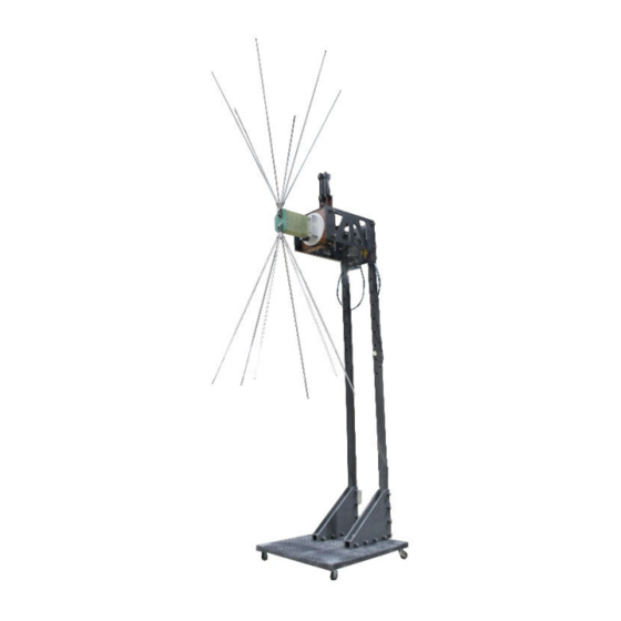
- Page 1 Model 3159C High-Power Biconical Antenna User Manual Introduction...
- Page 2 Introduction...
- Page 3 ETS-Lindgren Inc. reserves the right to make changes to any products herein to improve functioning or design. Although the information in this document has been carefully reviewed and is believed to be reliable, ETS-Lindgren does not assume any liability arising out of the application or use of any product or circuit described herein; nor does it convey any license under its patent rights nor the rights of others.
-
Page 4: Table Of Contents
Table of Contents Notes, Cautions, and Warnings ..........5 1.0 Introduction ................6 ETS-Lindgren Product Information Bulletin ........... 7 2.0 Maintenance ................. 8 Annual Calibration ..................8 Replacement Parts ..................8 Service Procedures ..................8 3.0 Specifications .............. -
Page 5: Notes, Cautions, And Warnings
Included text gives proper procedures. Warning: Denotes a hazard. Failure to follow instructions could result in SEVERE personal injury and/or property damage. Included text gives proper procedures. See the ETS-Lindgren Product Information Bulletin for safety, regulatory, and other product marking information. Introduction... -
Page 6: Introduction
This ensures high field strength at frequencies as low as 20 MHz. The design of the Model 3159C takes advantage of the wide beamwidth feature of a biconical antenna. In addition, the optimized design provides low VSWR and high radiation efficiency. -
Page 7: Ets-Lindgren Product Information Bulletin
The extensions should therefore only be used to fine-tune the performance of the antenna, with the benefit of measurement data taken in the actual operating chamber with a representative setup. ETS-Lindgren Product Information Bulletin See the ETS-Lindgren Product Information Bulletin included with your shipment for the following: Safety, regulatory, and other product marking information ... -
Page 8: Maintenance
118515 Bolt, M8 x 25, Hex, SS 930732 Washer, M8, Lock, Split, SS 930037 Service Procedures For the steps to return a system or system component to ETS-Lindgren for service, see the Product Information Bulletin included with your shipment. Maintenance... -
Page 9: Specifications
Average RF Input Power: 10 kW Maximum RF Input Power: 15 kW RF Connector: 1 5/8 in EIA flange Physical Specifications 3159C A ODEL NTENNA Length: 5.4 m (17.7 ft) Length without extension: 3.6 m (11.8 ft) Length with one extension: 4.5 m (14.8 ft) -
Page 10: Ferrite Floor
ERRITE LOOR Length: 130 cm (51.18 in) Width: 150.01 cm (59.06 in) 100 mm x 100 mm x 6.7 mm Individual tiles: (3.94 in x 3.94 in x 0.26 in) Weight: 113.40 kg (250 lbs) Specifications... -
Page 11: Mounting Instructions
Do not cross thread connections or permanent damage could occur. Mounting the Balun and Polarization Unit Due to the size of the Model 3159C biconical elements, you must mount the balun unit onto the pedestal prior to attaching the elements. -
Page 12: Mounting The Biconical Elements
Mounting the Biconical Elements 1. Once the balun unit is securely Insert element connected to the boom, align the into balun socket threads on one of the biconical elements with the receptacle on the end of the balun, and then turn the biconical element until it is firmly seated in the balun. -
Page 13: Removing The Connector
Removing the Connector Each side has six (6) main tubes each with two (2), 0.5m long screw on extensions. Remove the four (4) mounting bolts on the flange. Pull the connector firmly out of the brass yoke. Plug the connector into the yoke and replace the mounting hardware (hex bolt 930732 and lock washer 930037). -
Page 14: Operation
The Model 3159C pedestal has one air cylinder that controls the polarization movement of the antenna. The switch on the back of the pedestal toggles air control. Boresight adjustment is accomplished manually by loosening the four mounting screws so that the polarization unit can be tilted. -
Page 15: Performance
Performance The free space far field performance of the 3159 is very different to its performance in the near field semi-anechoic chamber environment under which it typically operates. In the EMC chamber there is more coupling to the chamber floor and the DUT which loads the antenna and could result in undesirable resonance effects that increase the VSWR of the antenna despite the isolating benefits of the balun. - Page 16 The performance of the 3159 antenna in a SAC depends on several factors. These include the overall size of the chamber, the effectiveness of the absorber treatment on all surfaces, especially those close to the antenna and the ground, height above the ground and size of the ferrite layout (if used) below the antenna. The variation in the VSWR performance can be seen in the following three examples of installations of the 3159 in chambers of various sizes, with different absorber treatments.
- Page 17 1.5m height, 1m distance, Figure 5: Measured VSWR in 10m EMC chamber at 1.5m height above ferrite tiles Figure 6: Measured VSWR in a very large SAC at 2.3m and 3.3m height above ferrite Operation...
- Page 18 Figure 7: Measured Ē field in a small EMC chamber with and without ferrite on floor Figure 8: Measured Ē field in small EMC chamber at 2.3m height above ferrite tiles Operation...
-
Page 19: Typical Calibration Data
20 log 10 ���� 20 log 10 �������� ���� ���� �� With this equation, you can calculate the forward power needed to generate 100 V/m at a given distance. Following is the performance for the Model 3159C at 3.5m: Operation... -
Page 20: Balun Vswr
VSWR ALUN VSWR taken August 2017 Operation...
Need help?
Do you have a question about the 3159C and is the answer not in the manual?
Questions and answers