Table of Contents
Advertisement
Quick Links
Advertisement
Table of Contents

Related Manuals for ETS-Lindgren BiConiLog 3142D


Summary of Contents for ETS-Lindgren BiConiLog 3142D
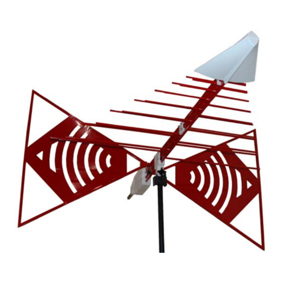
- Page 1 Model 3142D BiConiLog™ Antenna User Manual...
- Page 2 ETS-Lindgren L.P. reserves the right to make changes to any product described herein in order to improve function, design, or for any other reason. Nothing contained herein shall constitute ETS-Lindgren L.P. assuming any liability whatsoever arising out of the application or use of any product or circuit described herein.
- Page 3 January, 2001 Model 3142 information Edit/update February, 2003 Edit/update June, 2003 Update bowtie/antenna knob November, 2006 information Updated content to Model 3142D; December, 2008 rebrand Updated Specifications; updated May, 2009 Additional Mounting Options illustrations Added part numbers for optional October, 2009...
- Page 4 This page intentionally left blank.
-
Page 5: Table Of Contents
1.0 Introduction ................9 Optional End Plates ..................9 Tripod Options ..................... 10 ETS-Lindgren Product Information Bulletin ..........12 2.0 Maintenance ............... 13 Annual Calibration ..................13 Replacement and Optional Parts ..............14 ... - Page 6 This page intentionally left blank.
-
Page 7: Notes, Cautions, And Warnings
Included text gives proper procedures. Warning: Denotes a hazard. Failure to follow instructions could result in SEVERE personal injury and/or property damage. Included text gives proper procedures. See the ETS-Lindgren Product Information Bulletin for safety, regulatory, and other product marking information. - Page 8 This page intentionally left blank. viii |...
-
Page 9: Introduction
From 26 MHz to 60 MHz, the Model 3142D antenna with optional end plates exhibits an average 5.5 dB gain improvement. At some frequencies, a 10 dB gain improvement is achieved. -
Page 10: Tripod Options
10 dB improvement in low frequency transmit gain and receive antenna factor compared to a same length regular bow tie. With the end plates attached to the Model 3142D bow tie elements, the equivalent dipole electrical length is increased, which decreases resonant frequency and increases efficiency in the 20 MHz to 60 MHz range. - Page 11 • Model 7-TR—Constructed of PVC and fiberglass components, providing increased stability for physically large antennas. The unique design allows for quick assembly, disassembly, and convenient storage. Allows several different configurations, including options for manual or pneumatic polarization. Quick height adjustment and locking wheels provide ease of use during testing.
-
Page 12: Ets-Lindgren Product Information Bulletin
ETS-Lindgren Product Information Bulletin See the ETS-Lindgren Product Information Bulletin included with your shipment for the following: • Warranty information • Safety, regulatory, and other product marking information • Steps to receive your shipment • Steps to return a component for service •... -
Page 13: Maintenance
Before performing any maintenance, follow the safety information in the ETS-Lindgren Product Information Bulletin included with your shipment. Maintenance of the Model 3142D is limited WARRANTY to external components such as cables or connectors. If you have any questions concerning maintenance, contact ETS-Lindgren Customer Service. -
Page 14: Replacement And Optional Parts
• 106364 Thumbscrew, M4x12 (4) For additional/optional mounting hardware, see Additional Mounting Options on page 24. Service Procedures For the steps to return a system or system component to ETS-Lindgren for service, see the Product Information Bulletin included with your shipment. Maintenance... -
Page 15: Specifications
3.0 Specifications Electrical Specifications With Standard Bow Tie Elements / With Optional End Plates 26 MHz–6 GHz Frequency Range: 50 Ω Input Impedance (Nominal): 2:1 above 50 MHz VSWR (Average): 1 kW Maximum Continuous Power: 1.3 kW Peak Power: Directional Pattern Type: Linear Polarization:... - Page 16 This page intentionally left blank. Specifications...
-
Page 17: Assembly Instructions
4.0 Assembly Instructions Before connecting any components, follow the safety information in the ETS-Lindgren Product Information Bulletin included with your shipment. The Model 3142D BiConiLog™ Antenna consists of the following: • Antenna • Bow tie elements (2) • 10–32 thumbscrew knobs to attach bow tie elements (2) •... -
Page 18: Attach Bow Tie Elements
Attach Bow Tie Elements The Model 3142D ships with the bow tie elements detached. To attach the bow tie elements: For stability, mount the Model 3142D onto a tripod or tower. See Mounting Instructions on page 21 for the steps to mount the antenna. -
Page 19: Attach Optional End Plates
Attach Optional End Plates For protection, there is a black end cap on each of the bow tie elements. Use a Phillips screwdriver to carefully remove the four screws in each of the bow tie end caps. Remove the end caps. The end caps should be reinstalled when you are done using the optional end plates, so store the end caps and the screws in a safe place. - Page 20 This page intentionally left blank. Assembly Instructions...
-
Page 21: Mounting Instructions
Both horizontal and vertical polarization is easily accomplished when the Model 3142D with the optional end plates is mounted onto a tower, but vertical polarization on a tripod requires special consideration. Because immunity power requirements are many dB lower for vertical polarization, the optional end plates can be removed when mounting vertically on a standard tripod. -
Page 22: Using Included Mounting Adapters
Using Included Mounting Adapters The Model 3142D ships with these mounting adapters: • 100989 Polarizing Mounting Adapter with 7/8–14 thread receptacle If you need to convert the polarizing adapter to a 1/4–20 receptacle, insert the 1/4–20 thread insert into the polarizing adapter •... - Page 23 To attach the included adapters to the Model 3142D: Model 3142D mounted onto 4-TR using included 100989 Polarizing Mounting Adapter and 105861B 1/4–20 Thread Insert If required, insert the 1/4–20 thread insert into the polarizing adapter. Remove the mounting knob from the mounting bracket on the antenna.
-
Page 24: Using The Stinger To Mount To A Model 2175 Minimast
Using the Stinger to Mount to a Model 2175 MiniMast Do not use the stinger to mount the Model 3142D onto a 4-TR tripod. ° The stinger mount provides on-axis rotation during 90 horizontal or vertical polarization. The stinger enables you to mount the antenna directly to an ETS-Lindgren 7-TR Tripod or mast. - Page 25 1. Thread the antenna feed or receiving cable through the center of the boom so that the antenna connector emerges a few inches out of the clamp end of the boom. 2. Attach the cable to the Type N connector at the end of the stinger.
- Page 26 4. When you reach the back of the balun box, align it with the boom receptacle, and then slide the smaller portion of the balun box into the boom. This will prevent rotation of the antenna unless the boom is being polarized.
- Page 27 6. Secure the antenna by inserting the antenna mount knob through the boom and into the mounting adapter. Mounting Instructions...
- Page 28 Model 3142D mounted horizontally on Model 2175 Model 3142D rotated vertically on Model 2175 Mounting Instructions...
-
Page 29: Additional Mounting Options
Additional Mounting Options 4-TR M OUNTING PTIONS Following are additional options for mounting the Model 3142D onto an ETS-Lindgren 4-TR tripod. Contact the ETS-Lindgren Sales Department for information on ordering optional mounting hardware. Mounting Instructions... -
Page 30: 7-Tr And Mast Mounting Options
7-TR OUNTING PTIONS The stinger on the Model 3142D enables you to mount to antenna directly to an ETS-Lindgren 7-TR Tripod Positioner. However, following are additional options for mounting the Model 3142D onto an ETS-Lindgren 7-TR Tripod Positioner. Contact the... - Page 31 Mast refers to 2070 Series, 2075, and 2175 Antenna Towers. 7-TR refers to 109042, 106328, and 108197 booms: • 109042 boom—Straight boom; for general antenna mounting on a 7-TR • 106328 boom—Offset boom; for general antenna mounting on a 7-TR with pneumatic or manual polarization •...
- Page 32 Model 3142D mounted horizontally Model 3142D mounted vertically on 7-TR on 7-TR Mounting Instructions...
-
Page 33: 2X2 Boom Mounting Options
OUNTING PTIONS Following are additional options for mounting the Model 3142D onto a 2x2 boom. Contact the ETS-Lindgren Sales Department for information on ordering optional mounting hardware. 2x2 boom refers to a typical 2-inch by 2-inch boom. Mounting Instructions... - Page 34 This page intentionally left blank. Mounting Instructions...
-
Page 35: Application
1 V/m. For any other field strength not shown, multiply the power in watts by the desired E-field squared, or: P(E V/m) = E P(1 V/m) Actual transmitted field strength should be verified using an ETS-Lindgren electric field probe, or equivalent. Application... -
Page 36: With Optional End Plates
With Optional End Plates For emissions testing it is recommended that the Model 3142D BiConiLog™ Antenna be used without the optional end plates. The coupling of the endplates to ground will create higher uncertainty values, particularly in the vertical polarization. - Page 37 An estimate of the power required, taking VSWR into account, is obtained from: / {1-[(VSWR-1)/(VSWR+1)] = forward (amplifier output) power = new power, as discussed For IEC/EN 31000-4-3 type testing, the antenna tip can be placed at any distance between one and three meters from the EUT as long as the front face plane is illuminated according to the -0, +6 dB uniform field specifications.
- Page 38 This page intentionally left blank. Application...
-
Page 39: Typical Data
7.0 Typical Data Typical Antenna Factor Distance for the ANSI 3-meter and 10-meter calibrations is measured from the antenna midpoint, and for SAE 1-meter calibrations the distance is measured from the antenna tip. Midpoint is defined as half the distance between the small elements and the bow ties, which is about 45 cm from the small end tip. -
Page 40: Typical Gain
Typical Gain Typical Data... -
Page 41: Typical Gain With And Without End Plates
Typical Gain With and Without End Plates For frequencies above 60 MHz, use the Model 3142D BiConiLog™ Antenna without the end plates; additional gain is provided only when using end plates for frequencies below 60 MHz. Typical Data... -
Page 42: Typical Vswr
Typical VSWR Typical Data... -
Page 43: Appendix A: Warranty
Appendix A: Warranty See the Product Information Bulletin included with your shipment for the complete ETS-Lindgren warranty for your Model 3142D BiConiLog™ Antenna. 3142D URATION OF ARRANTIES FOR ODEL All product warranties, except the warranty of title, and all remedies for warranty failures are limited to two years.
Need help?
Do you have a question about the BiConiLog 3142D and is the answer not in the manual?
Questions and answers