
Subscribe to Our Youtube Channel
Related Manuals for ETS-Lindgren BiConiLog 3140


Summary of Contents for ETS-Lindgren BiConiLog 3140
- Page 1 Model 3140 BiConiLog Antenna ™ MANUAL © EMC TEST SYSTEMS, L.P. – MARCH 2002 REV C – PN 399258...
- Page 2 © Copyright 2002 by EMC Test Systems, L.P. All Rights Reserved. No part of this document may be copied by any means without written permission from EMC Test Systems, L.P. E-MAIL & INTERNET Support@ets-lindgren.com http://www.ets-lindgren.com FINLAND SINGAPORE 1301 Arrow Point Dr., Cedar Park, TX 78613...
-
Page 3: Table Of Contents
MODEL 3140 BICONILOG™ ANTENNA Table of Contents INTRODUCTION......................1 ASSEMBLY INSTRUCTIONS ..................4 MOUNTING INSTRUCTIONS ..................8 APPLICATION......................12 TYPICAL DATA ......................14 SPECIFICATIONS......................18 MAINTENANCE ......................19 WARRANTY STATEMENT..................20 © EMC TEST SYSTEMS, L.P. – MARCH 2002 REV C – PN 399258... - Page 4 MODEL 3140 BICONILOG ™ ANTENNA © EMC TEST SYSTEMS, L.P. – MARCH 2002 REV C – PN 399258...
-
Page 5: Introduction
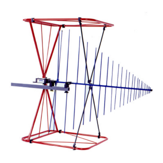
MODEL 3140 BICONILOG™ ANTENNA Introduction INTRODUCTION The ETS-Lindgren EMCO brand Model 3140 is a high- field addition to the popular bow-tie/log periodic combination BiConiLog family, providing the highest field-to-power ratio at low frequencies of any of the BiConiLog™ antennas. The Model 3140 is designed... - Page 6 Introduction MODEL 3140 BICONILOG™ ANTENNA useful low frequency range of the typical LPDA's from 100 MHz down to 26 MHz. At 26 MHz, an efficient single dipole type antenna must be over 5 meters long, whereas suitable performance is obtained here with a 1.6 meter long bow-tie.
- Page 7 150 MHz the radiation in the plane of the elements is directional. The antenna has dual mounting bracket and 1/4x20 UNC knob for attaching to ETS-Lindgren tripod and tower adapters. The brackets are spaced to align with the mounting holes on the Model 7-TR tripod and the ETS- Lindgren towers.
-
Page 8: Assembly Instructions
Assembly Instructions MODEL 3140 BICONILOG™ ANTENNA ASSEMBLY INSTRUCTIONS The Model 3140 Antenna consists of the following (shipped unassembled): 1 ea. Boom Assembly 2 ea. Bow-tie Elements 2 ea. Long T leg Elements 2 ea. V Elements 4 ea. Diagonal Struts 2 ea. - Page 9 MODEL 3140 BICONILOG™ ANTENNA Assembly Instructions Step 2. Once you have attached both bow-tie elements; with both hands, rotate the antenna and bow-tie into a vertical position resting on a flat surface (see Figure 2). The antenna can now rest by itself on the feet of the balun box, and the bottom edge of the bow-tie elements.
- Page 10 Assembly Instructions MODEL 3140 BICONILOG™ ANTENNA Step 5. The four diagonal struts should be installed. Loosen the thumbscrews at the mount on the T legs and at the boom mounts to install the strut ends. Place the pocket of the straight end facing the raised face of each mount and tighten the thumbscrew to lock in place (see Figure 3).
- Page 11 FIGURE 4 – Assembly Step 6 The antenna is now ready for mounting on a boom of a stand such as the ETS-Lindgren 7-TR or mast such as the ETS-Lindgren 2070 series. See the next section “Mounting Instructions” for more details.
-
Page 12: Mounting Instructions
Step 1. Install the antenna adapters onto the two mount brackets on the antenna boom (see Figure 5). These have a 7/8” threaded hole for an ETS-Lindgren mount knob. Install the threaded insert adapter into the 7/8” hole if a ¼” thread is required on the mounting stand or mast. - Page 13 MODEL 3140 BICONILOG™ ANTENNA Mounting Instructions Step 2. The antenna can be mounted on standard ETS-Lindgren perforated cross booms using two 7/8” mount knobs through the 2” square boom (see Figure 6). FIGURE 6 – Attachment of Model 3140 to perforated offset boom.
- Page 14 Mounting Instructions MODEL 3140 BICONILOG™ ANTENNA FIGURE 7 – Attachment of Model 3140 to Model 7-TR heavy duty antenna stand FIGURE 8 – Attachment of Model 3140 to Model 2075 MiniMast © EMC TEST SYSTEMS, L.P. – MARCH 2002 REV C – PN 399258...
- Page 15 MODEL 3140 BICONILOG™ ANTENNA Mounting Instructions FIGURE 9 – Attachment of Model 3140 to Model 2070 or 2071 Tower © EMC TEST SYSTEMS, L.P. – MARCH 2002 REV C – PN 399258...
-
Page 16: Application
Both horizontal and vertical polarization is easily accomplished when the Model 3140 is mounted on an ETS-Lindgren tower. The Model 7-TR tripod is designed specifically for the T bow-tie BiConiLog™ antennas to allow easy polarization changes, and with the air polarization option can provide automated polarization using a Model 2090 controller. - Page 17 80% amplitude modulation, multiply the result by 3.24 (1.8 ). Actual transmitted field strength should be verified using an ETS-Lindgren Model 7200 series electric field probe or equivalent. Figures 14 and 15 show power requirements for the lower frequencies at 3 meters based on measurements using a field probe on an OATS over both conducting ground and a (2.4m)
-
Page 18: Typical Data
Typical Data MODEL 3140 BICONILOG™ ANTENNA TYPICAL DATA Figure 10 shows the typical VSWR for the Model 3140 in the frequency range from 26-2000 MHz. Figure 11 shows the typical horizontal antenna factors for the 3140 in the same range. The separation distance for the ANSI C63.5 3 and 10 meter calibrations is measured from the antenna midpoint, while for SAE/ARP-958 1 meter calibrations the distance is measured from the antenna tip. - Page 19 MODEL 3140 BICONILOG™ ANTENNA Typical Data 1000 2000 Frequency (MHz) FIGURE 10 - Model 3140 typical VSWR. 10 m 1000 2000 Frequency (MHz) FIGURE 11 – Model 3140 typical antenna factors. © EMC TEST SYSTEMS, L.P. – MARCH 2002 REV C – PN 399258...
- Page 20 Typical Data MODEL 3140 BICONILOG™ ANTENNA 10 V/m 80% AM 10 V/m 1 V/m 80% AM 3 V/m 1 V/m 80% AM 1 V/m 0.01 0.005 1000 2000 Frequency (MHz) FIGURE 12 – Model 3140 typical 1 meter forward power based on 1 meter antenna factor.
- Page 21 MODEL 3140 BICONILOG™ ANTENNA Typical Data 1000 10 V/m 80% AM 10 V/m 1 V/m 80% AM 3 V/m 1 V/m 80% AM 1 V/m 0.01 Frequency (MHz) FIGURE 14 – Model 3140 typical 3 meter forward power measured over ferrite tile. 1000 10 V/m 80% AM 10 V/m...
-
Page 22: Specifications
Specifications MODEL 3140 BICONILOG™ ANTENNA SPECIFICATIONS Electrical (nominal) Frequency range 26 - 2000 MHz 50 Ω Input impedance VSWR 2:1 average CW power 750 W Symmetry +/- 0.5 dB Connector Type N female Physical Height (T bow-tie) 76.65 cm 30.18 in Width (T bow-tie) 161.5 cm 63.60 in... -
Page 23: Maintenance
MODEL 3140 BICONILOG™ ANTENNA Maintenance MAINTENANCE The ETS-Lindgren EMCO brand Model 3140 was designed to be used for Immunity testing. Because the testing is for immunity, the generated field is measured with a calibrated field probe, not the Model 3140. Thus it is not required that the Model 3140 be recalibrated regularly. -
Page 24: Warranty Statement
Warranty Statement MODEL 3140 BICONILOG™ ANTENNA WARRANTY STATEMENT EMC Test Systems, L.P., hereinafter referred to as the Seller, warrants that standard EMCO products are free from defect in materials and workmanship for a period of two (2) years from date of shipment. Standard EMCO Products include the following: v Antennas, Loops, Horns v GTEM cells, TEM cells, Helmholtz Coils v LISNs, PLISNs, Rejection cavities &...
Need help?
Do you have a question about the BiConiLog 3140 and is the answer not in the manual?
Questions and answers