
Related Manuals for Extron electronics MediaLink MLC 62 IR D


Summary of Contents for Extron electronics MediaLink MLC 62 IR D
- Page 1 User Guide MediaLink ® MLC 62 Series MediaLink Controllers 68-1731-01 Rev. B 07 10...
- Page 2 Safety Instructions • English Warning This symbol is intended to alert the user of important operating and mainte- Power sources • This equipment should be operated only from the power source indicated on the product. This nance (servicing) instructions in the literature provided with the equipment. equipment is intended to be used with a main power system with a grounded (neutral) conductor.
- Page 3 NOTE: This unit was tested with shielded cables on the peripheral devices. Shielded cables must be used with the unit to ensure compliance with FCC emissions limits. Copyright © 2010 Extron Electronics. All rights reserved. Trademarks All trademarks mentioned in this manual are the properties of their respective owners.
-
Page 5: Table Of Contents
Contents Software-based Configuration ....35 Introduction ............1 About the MLC 62 Configuration Program ..35 About This Guide ..........1 PC System Requirements ....... 35 About the MLC 62 Series MediaLink Controllers . 1 Installing the Configuration Software ....36 MLC 62 Models .......... - Page 6 Extron MLC 62 Series MediaLink Controllers • Contents...
-
Page 7: Introduction
Introduction This section gives an overview of the guide and describes the MLC 62 Series MediaLink ® Controllers and their features. Topics that are covered include: About This Guide About the MLC 62 Series MediaLink Controllers System Requirements About This Guide This guide provides detailed information and best practice recommendations about cabling and configuring the Extron MLC 62 Series MediaLink Controllers, and reference information... - Page 8 The four MLC 62 models have the same button functionality and use the same configuration software. All models can be controlled by pressing the front panel buttons or via a host device using RS-232 communication and simple ASCII commands (Simple Instruction Set, SIS ™...
-
Page 9: Features
Additional button sets are available for the EU and MK models, labeled in English (the default) and other languages. Refer to the Extron Web site at www.extron.com ordering information. Features Some of the features of MLC 62 include: Customizable buttons — Eight buttons are standard on the MLC 62 and are prelabeled for power on, power off, volume up, volume down, and input selections. -
Page 10: Mlc 62 Configuration Software
Front panel security lockout — If the MLC 62 RS D is installed in an unsecured environment where easy access is not desirable, a security lockout feature can be implemented to lock out all front panel controls. Activity LED — An LED on the MLC front panel lights red, green, or amber to indicate button presses, the transfer of data, front panel lockout, and other actions. -
Page 11: Application Diagrams
Application Diagrams Relay V ID RS-232 or IR Projector Control RS-232 Switcher Control Extron MLC 62 RS D ® MediaLink Controller Screen Video Control Projector U TP IF IE R IG /I R -2 32 IN PU D IO LI N X/ M -4 2d D IO... -
Page 12: System Requirements
Audio RS-232 Display Control Audio Video Audio Laptop Relay V I D Projector with Switched Extron Audio Output Extron IF IE W ER I PO M IN MLC 62 RS EU SI 3 Screen Extron MediaLink Controller Surface-Mount ® Control MPA 122 Speakers Mini Power... -
Page 13: Features, Installation, And Operation
Features, Installation, and Operation This section describes the front, side, and rear panel features of the four MLC 62 models, and provides procedures for installing and operating the controllers. Topics that are covered include: Installation Checklist Panels and Connectors Installation Configuring the MLC 62 via the USB Port Mounting the MLC 62 Accessing Covered Panel Features After Mounting... -
Page 14: Panels And Connectors
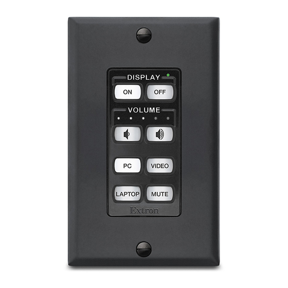
z “Connecting Power to the Wire and connect the MLC power supply. (See 62,” later in this section.) Connect all other power cords and turn on all the devices, including the MLC. Connect a configuration cable from the computer to the MLC 62 by doing either of the following: Connect a USB A to mini B cable to the MLC USB configuration port and to a USB port on your computer. - Page 15 MLC 62 RS D The MLC 62 RS D front panel, by default, contains eight buttons and the indicator LEDs for volume and activity. Other controls and connectors are located on the front panel behind the MLC wallplate. To access these features that are covered during normal operation, you must remove the wallplate.
- Page 16 MLC 62 RS EU and MLC 62 RS MK The MLC 62 RS EU and MLC 62 RS MK front panels contain the same buttons and indicators as the MLC 62 D models. Other connectors and controls are on the left side panel;...
- Page 17 Input selection buttons — These buttons can be used to select the desired audio or video input for the connected device or for a variety of other functions. By default they are set up as follows: RS models: Three of these buttons are set to input mode, meaning that they are a mutually exclusive group —...
-
Page 18: Buttons
Buttons The MLC 62 Series controllers have backlit, prelabeled buttons. The front panel button illumination provides status on what the MLC 62 is doing. The buttons are lit while the MLC has power. When a button has been pressed and is active or on, it lights brightly. While a button is inactive or off, it is lit dimly. -
Page 19: Rear Panel Features
Rear Panel Features See the wiring and installation sections, later in this section, for connection information. GROUND GROUND GROUND COMMON GROUND GROUND Tx/IR IR OUT GROUND GROUND GROUND +12 VDC +12 VDC MLC 62 RS D Rear Panel MLC 62 IR D Rear Panel Figure 9. - Page 20 Relay ports (RS models only) — These relays allow control of room devices such as motorized screens, lights, and projector lifts. They are normally open relays and are rated at 24 V, 1 A. Low-power devices can be connected directly to the relay ports; devices requiring more than 24 V can be connected through a third-party low-voltage controller (LVC).
-
Page 21: Installation
Installation The MLC 62 D models can be installed in a standard one-gang electrical wall box or a one-gang Decora mounting bracket (“mud ring”). The MLC 62 RS EU can be installed in a one-gang EU junction box, and the MLC 62 RS MK can be installed in a one-gang MK junction box. - Page 22 To attach the faceplate, line up the pegs in upper-left and lower-right corners on the back of the faceplate with the two diagonal holes on the MLC main board. Press the faceplate onto the board with the pegs in the holes until the tabs at the top and bottom of the faceplate snap into their slots on the board.
-
Page 23: Replacing Buttons
Press inward with the screwdriver until the tab snaps free of its slot. Repeat steps a and b for the other tab on the same side of the faceplate. Lift the faceplate up and off the MLC. If the faceplate does not come free of the MLC, repeat steps a through c for the two tabs on the other side of the unit. -
Page 24: Wiring For Rs-232 Control (Rs Models Only)
Figure 16. Replacing a Button Pair Press the two buttons into the faceplate until the pegs on the membrane are seated in the corresponding holes. Repeat steps 2 through 4 for any additional buttons that you want to replace, then reattach the faceplate. -
Page 25: Wiring For Ir Control
Connecting to the IR/S port This port can be used for either IR or RS-232 unidirectional communication. To control a display device or switcher via RS-232 from this port, connect the device as follows: NOTE: In the configuration software, this port is called “IR Port” or “Serial Port,” depending on how you have configured it. -
Page 26: Wiring The Relays Port (Rs Models Only)
GROUND Example: The illustration below shows a single IR emitter connected to the IR/S port of an GROUND MLC 62 RS D. COMMON Ground ( ) GROUND IR Signal Tx/IR IR Emitter GROUND Unidirectional IR Output via White Striped Wire GROUND +12 VDC (15 m) -
Page 27: Wiring The Digital Input Port (Rs Models Only)
Wiring the Digital Input Port (RS Models Only) The Digital Input port on the MLC 62 rear panel lets you connect a switch or sensor to control other devices in the room that are connected to the MLC serial, IR, and relay ports. This port measures two states —... -
Page 28: Connecting Power To The Mlc 62
Pin: Ground Ground GROUND Rx Receive Transmit (Tx) Receive (Rx) 2 Transmit GROUND COMMON GROUND 9 pin HD Tx/IR MLC 62 RS D Rear Panel Connector GROUND GROUND To RS-232 Port on Computer +12 VDC or Control System Figure 23. Connecting a Host Computer or Control System to the Host/Config Port Plug the 3-pin connector into the Host/Config port on the MLC rear panel. -
Page 29: Configuring The Mlc 62 Via The Usb Port
CAUTIONS: The power supply must not be permanently fixed to the building structure or similar structures. The power supply must not be located within environmental air handling spaces or the wall cavity. The installation must be in accordance with the applicable provisions of the National Electrical Code ANSI/NFPA 70, Article 725 and the Canadian Electrical Code, Part 1, Section 16. - Page 30 Mini Type B Type A USB 1 USB Cable Ports MLC 62 RS EU or MLC 62 RS MK Left Side Panel Figure 27. USB Port Connection for MLC 62 RS EU and MLC 62 RS MK If this is the first time you have connected an MLC 62 to this USB port on your computer, the Found New Hardware Wizard opens.
- Page 31 Figure 29. Selecting the Radio Button to Install the USB Driver Automatically Your computer locates the driver needed for it to communicate with the MLC 62 via the USB port. This driver is loaded to the computer hard drive when the MLC 62 configuration program is installed.
-
Page 32: Mounting The Mlc 62
Mounting the MLC 62 When the system has been cabled, configured, and tested, the MLC can be installed in the wall or furniture. Mounting the MLC 62 D You can mount the MLC 62 D to a UL-approved electrical junction box or to a Decora mounting bracket (included). - Page 33 Mounting to a Decora Mounting Bracket A one-gang, Decora style mounting bracket (“mud ring”) is provided with the MLC 62 D models. If desired, you can mount the MLC to this type of bracket instead of to an electrical box. To mount the controller to a Decora style mounting bracket, follow these steps.
-
Page 34: Mounting The Mlc 62 Rs Eu And The Mlc 62 Rs Mk
Mounting the MLC 62 RS EU and the MLC 62 RS MK CAUTION: Ensure that the junction box is grounded properly. To mount the MLC 62 RS EU and MLC 62 RS MK to an electrical box: Attach the provided metal mounting bracket to the mounted electrical box using two of the included screws in the slots at the top and bottom of the bracket. -
Page 35: Mounting The Mlc 62 Eu In A Raceway Using Spacers (Optional)
Wall Wall Box Metal Bracket V I D Frame MLC 62 MK Figure 33. Mounting the MLC 62 RS MK to an External Electrical Box Mounting the MLC 62 EU in a Raceway Using Spacers (Optional) If you are experiencing difficulty with the MLC 62 EU staying in place when installed in a cable raceway, this may be due to a gap between the metal mounting bracket and the wall frame. -
Page 36: Accessing Covered Panel Features After Mounting
With the “Front” label toward you, place the metal mounting bracket onto the spacer so that the screw heads pass through two of the slotted holes in opposite sides of the bracket. NOTE: Ensure that the surface of the mounting bracket containing the word “Front”... -
Page 37: Accessing Mlc 62 Rs Eu And Mlc 62 Rs Mk Side And Rear Panel Features
D I S V I D MLC 62 D Wallplate Figure 35. Removing the MLC 62 D Wallplate Accessing MLC 62 RS EU and MLC 62 RS MK Side and Rear Panel Features To access the MLC 62 RS EU or MK side and rear panel features after the MLC has been mounted, you must remove the MLC from the installation surface, leaving the metal mounting bracket attached. -
Page 38: Front Panel Security Lockout (Executive Mode)
Front Panel Security Lockout (Executive Mode) To prevent accidental changes to settings, the MLC features a front panel security lockout (executive) mode for disabling access to controls. When front panel lockout is enabled, all the front panel buttons are disabled. If a button is pressed, all the buttons flash rapidly three times to indicate lockout, but no action occurs. -
Page 39: Ir Learning
You can perform two types of reset: Resetting to the default configuration: While the MLC is powered on, press and hold the Reset button. The Reset LED remains lit while the button is being held. After 3 seconds, the Reset LED blinks once. Release the button, then immediately (within 1 second) press it again and release it quickly (momentary press). - Page 40 IR Learning Transceiver 4"–14" (10–36 cm) MLC 62 RS EU and MLC 62 RS MK Left Side Panel Figure 39. IR Learning on an MLC 62 RS EU or MLC 62 RS MK To set up the MLC for IR Learning, see “Configuring Using IR Learning”...
-
Page 41: Software-Based Configuration
Software-based Configuration This section describes basic procedures for setting up and configuring the MLC using the MLC 62 Windows-based configuration program. For more detailed descriptions and additional procedures, refer to the MLC 62 help file, provided with your controller. The following topics are covered: About the MLC 62 Configuration Program Installing the Configuration Software... -
Page 42: Installing The Configuration Software
Installing the Configuration Software The software is provided on a DVD that is delivered with your MLC 62 unit. You can also download it free from the Extron Web site. Downloading and Installing the Software from the Web If you do not have the software on disk, download it to your computer from the Extron Web site as follows: www.extron.com and select the Download tab. -
Page 43: Obtaining Device Drivers
The easiest way to obtain the drivers for your devices is via the MLC 62 configuration program, as follows: Click Start > Programs > Extron Electronics > MLC 62 or double-click the MLC 62 software icon (shown at right) on your desktop to launch the MLC 62 software application. - Page 44 Make any desired optional selections: Select the Auto-check for new subscribed drivers check box if you want the MLC to check for and download any updates to your subscribed drivers. When a new version of any of your subscribed drivers is available on the Extron Web site, that new version is automatically downloaded when the configuration program is started.
-
Page 45: Downloading Drivers From The Disk
When the progress bar and the Status column indicate that the download has completed, click Close to close the Driver Subscription Download window. Figure 44. Driver Subscriptions Download Screen Showing a Completed Driver Download Click Close on the Driver Subscriptions window. Downloading Drivers from the Disk The software DVD provided with the MLC 62 contains the set of device drivers that are also available from the Web. - Page 46 Figure 45. MLC 62 Device Drivers Web Page From the DVD, you can download either the current Extron driver package (containing all IR and serial drivers that were available at the time the package was compiled) or one driver at a time. To download the driver package: Click Install driver package Version n.
- Page 47 NOTE: The DVD may contain additional drivers that became available after the current driver package was created. These new drivers may be on the DVD, but not have been incorporated into the driver package. If you want to ensure that you are getting all the drivers currently available, use the configuration program to download the drivers.
-
Page 48: Downloading Drivers From The Web
Downloading Drivers from the Web Drivers can also be obtained directly from the Extron Web site, as follows: Visit the Extron Web site at www.extron.com, and click the Download tab. Click the Device Drivers link on the left panel of the Download Center screen. From the drop-down menu on the Device Drivers screen, select MLC 62 Series. - Page 49 As you make each selection, the driver list below changes to display all available drivers meeting your selected criteria. Figure 48. Entering MLC 62 Driver Search Criteria Click on the device name whose driver you want to download. To download all the drivers in the current package, click the Download install for driver package (Version n) link.
-
Page 50: Creating An Mlc 62 Configuration - Getting Started
Creating an MLC 62 Configuration — Getting Started To use the MLC 62 to control devices, you must create one or more configurations for it, using the MLC 62 configuration program. A configuration is a set of specifications for button command assignments and port parameters that enable the MLC 62 to control your display device or switcher. - Page 51 On the Add Device window, enter a name for your MLC in the Device Name field. Select the MLC 62 model from the Select Model drop-down list. Figure 49. Add Device Window with Select Model Menu Displayed Click OK. The MLC 62 main window opens. Figure 50.
- Page 52 The following is displayed on the MLC 62 window: The device configuration name appears in the configuration tree in the left pane, with the names of the two ports (“Display” and “Serial” or “IR”) to which a device can be connected and controlled via IR or RS-232. The Front Panel tab is displayed in the main section of the window and contains a diagram representing the front panel of your selected MLC.
-
Page 53: Configuring The Ir And Serial Ports
Configuring the IR and Serial Ports The MLC 62 can control devices or switchers via two rear panel ports (the IR/S and RS-232 ports) on the RS models or via one port (the IR port) on the MLC 62 IR D. Use the MLC 62 configuration program to add the desired drivers to each IR or serial port to which a device (for example, your display or switcher) is connected. - Page 54 RS models only: (Optional) If you selected Serial Port (representing the IR/S port on the rear panel) in step 2 and want to configure the IR/S port for IR, select IR Port from the Port Type drop-down menu. When you select the IR Port option, Serial Port changes to IR Port on the device configuration tree.
-
Page 55: Configuring The Front Panel Buttons
Configuring the Front Panel Buttons The Front Panel tab on the MLC 62 window enables you to configure the buttons on the MLC 62 front panel. By clicking on a button, then making selections from the available menus, fields, and sub-tabs on the Front Panel tab, you can configure the corresponding button on the MLC front panel. - Page 56 Button flashing — The Flash sub-tab lets you add a flash period with a duration of 1 to 120 seconds to the button. You can also specify whether the button flashes rapidly or slowly during this delay period. During the flashing period, all front panel buttons are disabled and do not respond to pressing.
- Page 57 If you selected the Display (RS-232) port and want to keep the auto-filled commands, you need to add commands only to the last four buttons (by default configured as input selection buttons and labeled PC, Video, Laptop, and Mute). If you have selected the IR or Serial port, or if no power or volume commands are available with your driver, you need to configure all of the buttons.
- Page 58 Removing Commands To remove a command from a button: In the current command display field, click to highlight the command that you want to remove. Click the Remove button above the current command field. Reordering Commands When a button has multiple commands assigned to it, you can specify the order in which the commands are performed, as follows: In the current command display field, select the command that you want to move.
- Page 59 Single switch — Silver The button functions independently of all other buttons. A single press issues a single command. Single power — Gold and orange In Single Power mode, the button toggles between issuing a power on and a power off command.
- Page 60 Figure 54. Button Mode Menu on the Front Panel Tab Other button settings The Front Panel tab also provides the following settings for the buttons. Refer to the MLC 62 configuration software help file for detailed procedures for changing these settings.
- Page 61 Figure 55. Assigning a Relay to a Button To assign a relay to a button: On the front panel diagram, click the button to which the relay will be added. Click the Relay sub-tab. Select the relay mode (On, Off, Toggle, or Pulse) under the name of the relay port to which the device is connected (Relay1 or Relay2).
-
Page 62: Configuring The Digital Input Port
Configuring the Digital Input Port The Digital Input port on the MLC 62 rear panel lets you connect a switch or sensor to control other devices that are connected to the MLC serial, IR, and relay ports. On the Digital Input tab, you can assign commands to the high and low states of the Digital Input port. - Page 63 Time delays — The Time Delay sub-tab lets you insert a delay of a specified number of seconds between functions when multiple commands have been assigned to the port. You can set the amount of seconds that the MLC waits after issuing a command before it issues the next one.
- Page 64 To add commands to the Digital Input port: Connect a switch or sensor to the Digital Input port. See “Wiring the Digital Input Port” in the “Features, Installation, and Operation” section for more information about connecting to this port. On the MLC 62 window, select the Digital Input tab. Select the digital input mode from the drop-down menu at the top of the Digital Input tab.
- Page 65 Locking the front panel from the Digital Input port To lock and unlock the MLC front panel using the MLC 62 configuration software, modify the current configuration by adding Enable Front Panel and Disable Front Panel actions to the Digital Input port. For this method, a switch or sensor must be connected to the Digital Input port.
-
Page 66: Specifying Advanced Configuration Settings
Specifying Advanced Configuration Settings The Advanced Configuration tab provides some additional settings for the display device and the MLC. Make changes to these settings as desired. Figure 58. Advanced Configuration Tab Selecting display power settings In the Display Power Settings section of the Advanced Configuration tab, you can specify certain parameters for powering your display device on and off. -
Page 67: Configuring Using Ir Learning
Specifying the volume table resolution If the display device connected to your MLC 62 has a volume table in its driver, the display volume is increased or decreased by increments specified in the volume table each time a Volume button is pressed or pressed and held. You can configure the MLC to skip specified volume increments, essentially reducing the number of steps in the volume table, when the MLC buttons are pressed or held. - Page 68 Figure 59. “Select one of the starting options” Screen Depending on your selection, complete either of the following procedures. Creating a new IR driver Follow these steps if you want to create a new driver for your display device: On the “Select one of the starting options” screen, select the Create a new IR driver radio button, then click Next.
- Page 69 In the Version field, select or enter 1 if this is the first driver you have created for this device. If you are creating an additional driver for the same device but are keeping your original version as well, enter a different version number so you can differentiate between the two versions in the Available Drivers list.
- Page 70 Figure 62. Adding New Driver Functions to the “Edit the driver function list” Screen NOTES: Functions that you add are shown in gray, because they are not part of the default list. Functions whose names are shown in BLACK TEXT on this screen are part of the default template of functions for the driver.
- Page 71 When finished selecting and adding functions, click Next to continue. The “Specify the connection settings for the device” screen opens. If you have not already done so, connect a USB A to mini-B cable or an RS-232 cable between the appropriate USB or serial ports on your computer and the MLC 62. (See “Configuring the MLC via the USB Port”or “Wiring the Host/Config...
- Page 72 Click Next. The “Learn the selected IR function(s)” screen displays a list of the functions that you selected previously, with all their check boxes selected. (If you added a function on the “Edit the driver function list” screen but cleared its check box, it does not appear on this list.) For each new function, “Unlearned”...
- Page 73 A delay of approximately 3 seconds occurs before capturing begins, allowing you some time to aim the remote control at the IR sensor. The IR Learning Wizard then guides you through the process of learning the checked functions one by one, as follows: After 3 seconds, the name of the function being captured appears on the screen, along with a graphic indicating IR signals being sent.
- Page 74 NOTES: If you do not press a button within 7 seconds, or if the remote control is not correctly aimed at the MLC sensor, the capture procedure is timed out and the screen displays a message indicating that the function was not captured. The check box for the command remains checked, and the status for the function changes to “Failed.”...
- Page 75 When finished, click Next. A summary page appears, showing properties of the device for which you created the new IR driver and the number of functions learned. Figure 68. “Finished Learning IR Functions” Screen Example On the Finished Learning IR Functions screen, click Save to save the new driver. On the Save As window, save the new driver to your computer.
- Page 76 On the “Finished Learning IR Functions screen,” click Finish. The IR Learning Wizard closes. The new driver is now selectable from the Port Configuration tab. Editing an IR driver If the Extron driver for your display device does not contain all the commands that you need, you can use IR Learning to edit the driver (whether or not it was created via IR Learning).
- Page 77 The “Select one of the starting options” screen is redisplayed, with the path to the driver shown in the text field next to the Browse button. Figure 72. Path to the Driver in the Browse Field Click Next. The “Device Description” screen opens, showing the device type, manufacturer, model, and version of the driver you selected to edit.
- Page 78 If you want to make any changes to the Device Type, Manufacturer, or Model fields for your selected driver, select the Edit Device Description check box and select or enter your edits in these three fields. On the “Edit the driver function list” screen, the default template list of functions for your selected device is displayed.
- Page 79 Figure 75. New Driver Functions on the “Edit the driver function list” Screen NOTE: Functions that you add are shown in gray, because they are not part of the default list. Functions whose names are shown in BLACK TEXT on this screen are part of the default template of functions for the driver.
- Page 80 When finished selecting and adding functions, click Next to continue. The “Specify the connection settings for the device” screen opens. If you have not already done so, connect a USB A to mini-B cable or an RS-232 cable between the appropriate USB or serial ports on your computer and the MLC 62. (See “Configuring the MLC via the USB Port”or “Wiring the Host/Config...
- Page 81 Click Next. The “Learn the selected IR function(s)” screen displays a list of the functions that you selected previously, all with their check boxes selected. (If you added a function on the “Edit the driver function list” screen but cleared its check box, it does not appear on this list.) For each new function, Unlearned is displayed in the Status column.
- Page 82 A delay of approximately 3 seconds occurs before capturing begins, allowing you some time to aim the remote control at the IR sensor. The IR Learning Wizard then guides you through the process of learning the checked functions one by one: After 3 seconds, the name of the function being captured appears on the screen, along with a graphic indicating IR signals being sent.
- Page 83 NOTES: If you do not press a button within 7 seconds, or if the remote control is not correctly aimed at the MLC sensor, the capture procedure is timed out and the screen displays a message indicating that the function was not captured. The check box for the command remains checked, and the status for the function changes to Failed.
- Page 84 When finished, click Next. The “Finished Learning IR functions” summary screen appears, showing the properties of the device and the number of driver functions. Figure 81. “Finished Learning IR Functions” Screen Example On the “Finished Learning IR Functions” screen, click Save to save the changes made to the driver.
-
Page 85: Uploading A Configuration To The Mlc 62
Figure 82. Save As Window for New Drivers On the “Finished Learning IR Functions screen,” click Finish. The IR Learning Wizard closes. Uploading a Configuration to the MLC 62 Once a device configuration is completed, you must upload it to the MLC 62 in order for the MLC to be able to control your display device or switcher. - Page 86 Click Yes on the prompt window. The Device Connection window opens. Figure 83. Device Connection Window In the Communication Settings (left) section of the Device Connection window, select the port to which the MLC 62 that will receive the upload is connected: Select the USB Port or Serial Port radio button for the type of port to which the target MLC is connected on your computer.
-
Page 87: Configuration File Management Procedures
Configuration File Management Procedures The following operations can be performed on device configurations. Refer to the MLC 62 configuration program help file for details on these and other configuration-related procedures. Add a configuration to the current project: From the Edit menu or the Left Pane pop-up menu, select Add Device..., or click the Add a new device configuration button on the Main toolbar. - Page 88 Figure 84. Device Connection Screen In the Communication Settings (left) section of the Device Connection window, select the port to which the MLC is connected: Select the USB Port or Serial Port radio button for the type of port to which the target MLC is connected on your computer.
-
Page 89: Sis Control
The MLC sends the following copyright message only when it first powers on. (c) Copyright 2010, Extron Electronics, MLC 62, Vx.xx, 60-100n-nn where Vx.xx is the firmware version number and n is the MLC 62 model number. -
Page 90: Using The Command/Response Table
Using the Command/Response Table The command/response table on the following pages lists valid ASCII command codes, the responses of the MLC to the host, and a description of the command function or the results of executing the command. The ASCII to HEX conversion table below is for use with the command/response table. - Page 91 X2# = Status 0 = disengaged (default) 1 = engaged X2% = Firmware compatibility version number (a three digit number listed to three decimal places: nnn.nnn) X2^ = Device (image) compatibility version number (a three digit number listed to three decimal places: nnn.nnn) X4( = Default product name: MLC-62-RS or MLC-62-IR X21@ = LED status...
-
Page 92: Command/Response Table For Sis Commands
Command/response Table for SIS Commands ASCII Command Response Command Additional description (Host to unit) (Unit to host) Button selection Trigger.a.button Execute.the.command(s). .B.*. .BTNO. BtnoB.*. X! . programmed.to.button (This. command.produces.the.same. results.as.pressing.button on.the. front.panel).. .=.01,.02,.03,.04,.05,.06,.07,.or.08. NOTE: Use.the.MLC.62.Windows-based.configuration.software.to.configure.the.buttons.with.commands. Example Perform.commands.assigned.to. .B.*.5BTNO. BtnoB.*.05. button.5. Discrete audio volume adjustment (devices with volume tables) Set.volume.level Vol. - Page 93 ASCII Command Response Command Additional description (Host to unit) (Unit to host) Relay functions (continued) Force.relay.off .*.0.O Rly. .*.0. Set.relay.port. .to.remain.open. (off). View.relay.state Show.state. .of.relay.port. For. :.0.=.open;.1.=.closed. Digital Input data port View.digital.input.state View.status. .of.the.Digital. Input.port..For. :.0.=.low;. 1.=.high. Front panel lockout (executive mode) Unlock.front.panel.buttons.
- Page 94 ASCII Command Response Command Additional description (Host to unit) (Unit to host) Reset/Erase Configuration.reset Reset.the.MLC.62.configuration. .ZXXX. ZapXXX. to.the.factory.default. Query LED status X21@ X21@ View.LED.status .is.a.32-digit.number,.of. which.each.digit.represents.the. status.of.an.LED.on.the.MLC.62. front.panel.. X21@ The.LEDs.are.numbered.as.follows: ,.the.LEDs.are.represented. in.descending.order.from.32.to.1;. 1.=Transmit.red.. – DISPLAY that.is,.the.first.digit.represents. 2.=.Transmit.green. 3-6.=.Display.text.LEDs.1.through.4. LED.32,.the.second.digit. represents.LED.31,.and.so.on..The. 7.=.Button.row.1,.first.LED.
-
Page 95: Specifications, Part Numbers, And Accessories
Specifications, Part Numbers, and Accessories This section contains the specifications for all models of the MLC 62 and lists names and part numbers of included parts and optional accessories for the product. Topics that are covered include: Specifications — MLC 62 Series Part Numbers and Accessories Specifications —... - Page 96 Control — digital input monitoring port (RS models) Number/type ........1 digital input (configurable) Connector ........(1) 3.5 mm captive screw connector, 2 pole Digital inputs Input voltage range ....0-24 VDC Input impedance ...... 12k ohms Programmable pullup ....2k ohms to +5 VDC Threshold low to high ....
- Page 97 MLC 62 RS EU Faceplate ......2.2" H x 2.2" W x 0.3" D (1-gang EU, fits a Jung AS 500 wallplate) (5.5 cm H x 5.5 cm W x 0.7 cm D) Device ........ 1.9" H x 2.0" W x 0.7" D (4.8 cm H x 5.2 cm W x 1.8 cm D) (Overall rear dimensions, including connectors.
- Page 98 Product weight MLC 62 IR D, MLC 62 RS D ..1.0 lb (0.5 kg) MLC 62 RS EU ......1.0 lb (0.5 kg) MK models ......1.0 lb (0.5 kg) Shipping weight ......3 lbs (2 kg) Vibration ........ISTA 1 A in carton (International Safe Transit Association) Regulatory compliance Safety ........
-
Page 99: Part Numbers And Accessories
Part Numbers and Accessories Included Parts These items are included with the MLC 62 Series controller: MLC 62 RS D Replacement Part Included Parts Number MLC 62 RS D MediaLink Controller 60-1005-02 (Includes 1 black and 1 white eight-button faceplate) 12 VDC, 1 A external power supply (PS 1210C) 70-775-01 Front faceplate, black, eight-button... - Page 100 MLC 62 RS EU Replacement Part Included Parts Number MLC 62 RS EU MediaLink Controller (RAL9010 white) 60-1005-35 (Includes 1 six-button and 1 eight-button faceplate) 12 VDC, 1 A external power supply (PS 1210C) 70-775-01 Front faceplate, 6 button (RAL9010 white) Front faceplate, 8 button (RAL9010 white) Jung AS500 wall frame (RAL9010 white) Extron Tweeker (slotted Philips #1 screwdriver)
-
Page 101: Accessories
Accessories These optional items can be ordered separately: Part Accessories For Model Number English button kit MLC 62 RS EU, 70-728-01 (MLC 62 RS EU and MLC 62 RS MK models) MLC 62 RS MK French/German button kit MLC 62 RS EU, 70-728-11 (MLC 62 RS EU and MLC 62 RS MK models) MLC 62 RS MK... - Page 102 Extron Electronics makes no further warranties either expressed or implied with respect to the product and its quality, performance, merchantability, or fitness for any particular use. In no event will Extron Electronics be liable for direct, indirect, or consequential damages resulting from any defect in this product even if Extron Electronics has been advised of such damage.
Need help?
Do you have a question about the MediaLink MLC 62 IR D and is the answer not in the manual?
Questions and answers