Advertisement
Setup Guide — MLC 206
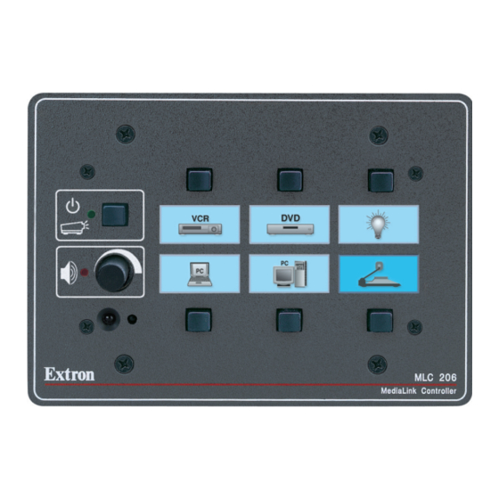
The Extron MediaLink
remote control of a display device, contact closure control of items in a room, tally
outputs, and MediaLink Switcher control.
This guide provides instructions for an experienced installer to set up and operate
the MLC 206 MediaLink Controller.
When possible in the following pages, line drawings are used to clarify steps
discussed in the text.
MLC 206 typical application diagram
Controller (MLC 206) provides infrared (IR) and RS‑232
™
Screen
Control
Projector
Control
Extron
Switcher
VCR
DVD
UT
TP
ED
OU
IFI
70V
AM
PL
8 ohm
NO
4 ohm
VID
EO
MO
M
COM
V
YU
B
O
RS
232
RG
S-V
IDE
E
R-Y
K
SUR
Switcher
LIN
E
T CLO
H/
Y
CO
MM
C
D
CON
TAC
HV
A
B
T
R
Y
OU
AU
DIO
R
V
L
5
C
INP
UT
IX
G
B-Y
AU
X/M
R
L
UT
4
CT
S
RN
INP
EF
FE
RE
TU
B
ND
SE
R
L
3
R
INP
UT
L
Control
UT
2
INP
R
B
L
1
R-Y
UT
INP
EO
Y
VID
R
L
R-Y
B-Y
VID
EO
Y
R
L
R
L
R
L
50/6
0 Hz
0.2A
-240
V
100
Document
Camera
Lighting
Control
p
p t o
L a
D
D V
R
V C
Y
P LA
D IS
W E
R
P O
6
2 0
C
M L
M E
LU
VO
/
M AX
M IN
n
t r o
E x
Extron MLC 206
Laptop
68-601-50
Rev. A
11 09
Advertisement
Table of Contents

Subscribe to Our Youtube Channel
Related Manuals for Extron electronics MEDIALINK MLC 206


Summary of Contents for Extron electronics MEDIALINK MLC 206
- Page 1 Setup Guide — MLC 206 The Extron MediaLink remote control of a display device, contact closure control of items in a room, tally outputs, and MediaLink Switcher control. This guide provides instructions for an experienced installer to set up and operate the MLC 206 MediaLink Controller.
-
Page 2: Step 1 - Computer Connection
MLC 206 Setup Guide, cont’d Step 1 — Computer Connection The MLC 206 must be connected to a PC in order to configure the controller. The configuration port, shown in the rear panel view below, is used for system control and for loading configuration and driver files into the MLC. -
Page 3: Step 2 - Software Installation
3. To power the MLC, connect a 12 VDC power supply or an optional MediaLink Switcher (MLS) to the MLS/Power port, and connect the power supply or the switcher to a power source. MediaLink Switcher MLC/RS-232 +12VDC Ground ( ) Receive (Rx) Transmit (Tx) A ground wire must be connected... - Page 4 MLC 206 Setup Guide, cont’d Step 3 — Setting up projector control Device drivers allow the MLC 206 to control projectors and other source devices via RS‑232 or IR. N It is strongly recommended that an RS-232 control (filenameRS1.mll) file for controlling a projector be used whenever possible. To load a driver and configure the MLC 206: 1.
-
Page 5: Step 4 - Ir Learning
3. Configure the buttons. Use the drop‑down box associated with each button to select the command to be issued or function to perform, as shown at right. Each configured button has a green or red dot on it. N If a button has been previously configured, it will have a red (IR) or green (RS-232) dot to indicate that an IR or RS-232 code has been associated with it. - Page 6 MLC 206 Setup Guide, cont’d 3. Click on the button labeled Learn IR to Button. A dialog box appears indicating the button to which IR codes will be learned. 4. Click on OK to begin the learning process. During IR learning hold the device remote control 4 inches to 14 inches (10 cm to 36 cm) away from and directly in front of the MLC’s IR pickup device.
-
Page 7: Step 5 - Completing The Installation
Step 5 — Completing the installation 1. Save the configuration by selecting Save CONFIGURATION as..., and name it appropriately. 2. Connect the MLC 206 to the projector for RS‑232 projector control. a. Disconnect the power from the MLC (and the optional MediaLink Switcher, if applicable) and from the projector. - Page 8 MLC 206 Setup Guide, cont’d The UC cable pin assignments are shown in the following illustration. To the MLC 206 Black Grey Purple Blue Green Yellow Orange Brown Color Pin # UC 50', 100' Cable Color Codes 3. Install the IR Emitter(s) in the IR port as shown in the following illustration, and attach the head of each IR Emitter to an IR‑controlled device (VCR, DVD player, projector).
Need help?
Do you have a question about the MEDIALINK MLC 206 and is the answer not in the manual?
Questions and answers