Extron electronics MediaLink MLC 52 IR User Manual
Hide thumbs
Also See for MediaLink MLC 52 IR:
- User manual (124 pages) ,
- Brochure & specs (6 pages) ,
- Quick start manual (17 pages)

Related Manuals for Extron electronics MediaLink MLC 52 IR


Summary of Contents for Extron electronics MediaLink MLC 52 IR
- Page 1 im Vertrieb von CAMBOARD Electronics MLC 52 Series MediaLink ™ Controllers 68-1079-01 Rev. C 04 06 www.camboard.de Tel. 07131 911201 ce-info@camboard.de Fax 07131 911203...
- Page 2 im Vertrieb von CAMBOARD Electronics Precautions Safety Instructions • English Warning Power sources • This equipment should be operated only from the power source indicated on the product. This symbol is intended to alert the user of important operating and maintenance This equipment is intended to be used with a main power system with a grounded (neutral) (servicing) instructions in the literature provided with the equipment.
-
Page 3: Table Of Contents
im Vertrieb von CAMBOARD Electronics Table of Contents Chapter 1 • Introduction ....................... 1-1 About the MLC 52 Series ....................1-2 Features and Options ......................1-2 Standard features ......................1-2 Options and accessories ..................... 1-3 MLC 52 Application Examples ..................1-4 Chapter 2 •... - Page 4 im Vertrieb von CAMBOARD Electronics Table of Contents, cont’d Using the MLC 52 VC Models with the MPA Series Power Amplifiers ... 3-10 Requirements for the MLC 52 with volume control knob ..........3-10 Wiring and connections for the MLC 52 VC models ............3-11 Configuring the MLC 52 IR and MLC 52 RS VOL buttons ..........
- Page 5 im Vertrieb von CAMBOARD Electronics Key to file names ....................... 5-6 Configuring the controller ....................5-7 Overview of the Controller (MLC) Config. tab ............5-7 Saving and restoring the configuration ..............5-8 Saving a configuration ..................5-8 Restoring a configuration ..................5-9 Assigning functions to buttons using IR drivers ............
- Page 6 im Vertrieb von CAMBOARD Electronics Table of Contents, cont’d Appendix B • Dimensions and Templates ..............B-1 Dimensions ..........................B-2 Standard MLC 52 IR and MLC 52 RS (one-gang size) ............B-2 MLC 52 IR VC and MLC 52 RS VC (two-gang size) ............B-3 Templates ..........................
-
Page 7: Chapter 1 • Introduction
im Vertrieb von CAMBOARD Electronics ™ MLC 52 Series MediaLink Controller Chapter One Introduction About the MLC 52 Series Features and Options MLC 52 Application Examples www.camboard.de Tel. 07131 911201 ce-info@camboard.de Fax 07131 911203... -
Page 8: About The Mlc 52 Series
im Vertrieb von CAMBOARD Electronics Introduction About the MLC 52 Series The Extron MediaLink™ Controller 52 (MLC 52) provides infrared (IR) and/or RS-232 remote control of a projector or plasma display. It is an economical, compact (one-gang or two-gang sized), easy-to-use controller for use with audiovisual equipment in sites such as an elementary or high school classroom, or a small conference room. -
Page 9: Options And Accessories
im Vertrieb von CAMBOARD Electronics Front panel configuration port — This serial port enables advanced configuration, driver downloads, and firmware updates to be performed from the front panel without the need to remove the controller from its mounting. The optional Extron configuration cable (part #70-335-01) connects the MLC 52 to the PC’s RS-232 port. -
Page 10: Mlc 52 Application Examples
im Vertrieb von CAMBOARD Electronics Introduction, cont’d MLC 52 Application Examples IR or RS-232 Control Projector w/ Internal Speakers V I D Extron MLC 52 Basic MediaLink Controller VGA w/ Audio Cable Composite Audio RCA Application diagram for a standard (1-gang sized) MLC 52 VGA w/ Extron Audio Cable... -
Page 11: Chapter 2 • Installation
im Vertrieb von CAMBOARD Electronics ™ MLC 52 Series MediaLink Controller Chapter Two Installation Installation Overview UL Requirements Installation Procedures www.camboard.de Tel. 07131 911201 ce-info@camboard.de Fax 07131 911203... -
Page 12: Installation Overview
im Vertrieb von CAMBOARD Electronics Installation Installation Overview Installation and service must be performed by authorized personnel only. UL CAUTION listed electrical boxes are recommended. See UL Requirements, on the next page. To install and set up the MLC, follow these steps: If applicable, prepare the installation site: cut a hole in the wall, install the electrical box or mounting bracket (mud ring), and prepare the cables. -
Page 13: Ul Requirements
im Vertrieb von CAMBOARD Electronics UL Requirements The Underwriters Laboratories (UL) requirements listed below pertain to the installation of the MLC into a wall or furniture. This unit is not to be connected to a centralized DC power source or used beyond its rated voltage range. -
Page 14: Replacing The Faceplate
im Vertrieb von CAMBOARD Electronics Installation, cont’d Replacing the faceplate and button labels The MLC’s faceplate and the backlit button labels can be replaced. You can replace the provided plastic faceplate with an optional metal one — the MLM 52 1GWP one-gang metal faceplate (part #70-528-02 or -03) or the MLM 52 VC two-gang metal faceplate (part # 70-538-02 or -03), both of which are available in black or white. - Page 15 im Vertrieb von CAMBOARD Electronics Remove the button assembly by inserting a small, flat-bladed screwdriver, such as an Extron Tweeker, between the button’s base and the diffuser to gently pry the button assembly off the button plunger, as shown in the drawing at right. Locate the small corner notch on the lens cap, and slide the screwdriver between the lens cap and the diffuser.
-
Page 16: Mounting An Electrical Box
im Vertrieb von CAMBOARD Electronics Installation, cont’d Mounting an electrical box If you want to install the MLC 52 in an electrical box (in a wall or in furniture), follow these steps: Refer to the appropriate template diagram (later in this manual) to find out the dimensions of the opening required for the size of the wall box that you are using. -
Page 17: Rear Panel/Cable Connections
im Vertrieb von CAMBOARD Electronics • If you are attaching the wall box to wood, use four #8 or #10 screws or 10-penny nails. A minimum of ½ inch (1.3 cm) of screw threads must penetrate the wood. • If you are attaching the wall box to metal studs or furniture, use four #8 or #10 self-tapping sheet metal screws or machine bolts with matching nuts. - Page 18 im Vertrieb von CAMBOARD Electronics Installation, cont’d VOL/ MUTE + 10V 2 3 4 MLC 52 VC rear view IR Learning indicators — Each button on the MLC front panel has four memory blocks, which can be programmed with up to four IR (or RS-232) commands.
-
Page 19: Wiring The Control Connector
im Vertrieb von CAMBOARD Electronics Volume control (VC faceplate only) — Connect this volume control connector to the MPA 122 or MPA 181T audio amplifier to enable the volume control knob on the MLC 52 to raise and lower the volume on the display device via the MPA. -
Page 20: Wiring For Ir Control
im Vertrieb von CAMBOARD Electronics Installation, cont’d Wiring for IR control If you intend to control the projector via IR, you can connect Extron IR emitters or an IR Broadcaster to the IR Out pin on the display and source control connector to control display and/or input devices via infrared commands from the MLC. -
Page 21: Wiring For Rs-232 Control (Rs Models Only)
im Vertrieb von CAMBOARD Electronics Wiring for RS-232 control (RS models only) The MLC 52 RS and the MLC 52 RS VC send out RS-232 commands via the Tx port for controlling a projector or a plasma display. If you have an RS model and want to control the display device via RS-232, connect a cable between the device and this 3.5 mm, 6-pole direct insertion captive screw connector. -
Page 22: Wiring For Ir Remote Control
im Vertrieb von CAMBOARD Electronics Installation, cont’d Wiring for IR remote control An optional IR Link or IRL 20 can be connected to the IR In pole of the control connector to enable the MLC to receive IR signals from the IR 452. Only one IR Link or one IRL 20 can be attached to the MLC 52. -
Page 23: Wiring The Irl 20
im Vertrieb von CAMBOARD Electronics Wiring the IRL 20 The Extron IRL 20 is a hardwired IR signal receiver, which can be used with the MLC 52 and the IR 452 remote control. The IRL 20 receives a signal via its front panel from the IR 452 remote control, and outputs a modulated IR signal via an IR Emitter or the IR Link. -
Page 24: Wiring The Power Connector
im Vertrieb von CAMBOARD Electronics Installation, cont’d Wiring the power connector The control connector also contains a power connector for the MLC 52. Connect the supplied external 12 VDC power supply to this port to power the MLC as shown in the following diagram. Ground ( ) +12 VDC input An External... -
Page 25: Mounting The Mlc 52
im Vertrieb von CAMBOARD Electronics Mounting the MLC 52 Once the system has been cabled, configured (see chapter 5, Serial Communication), and tested, the controller can be installed in the wall or furniture. Mounting the MLC to an electrical box or mounting bracket You can mount the MLC 52 in an electrical box or a mounting bracket. -
Page 26: Mounting The Mlc To A Wall Or Furniture
im Vertrieb von CAMBOARD Electronics Installation, cont’d Wall Extron Wall Mounting Bracket D I S V I D MLC 52 Mounting the MLC 52 to a mounting bracket Mounting the MLC to a wall or furniture With all cables attached to the MLC and power disconnected at the source, insert the MLC into the wall or furniture. -
Page 27: Chapter 3 • Operation
im Vertrieb von CAMBOARD Electronics ™ MLC 52 Series MediaLink Controller Chapter Three Operation Projector Control Front Panel Features and Operation Configuring the MLC 52 Using IR Using the MLC 52 VC Models with the MPA Series Power Amplifiers Powering the Projector/Display On and Off Selecting Inputs Operating the MLC 52 Using IR Remote Control Resetting... -
Page 28: Projector Control
im Vertrieb von CAMBOARD Electronics Operation Projector Control The MLC 52 IR models can control a projector or other display device by using IR. The RS models can control a display device by IR or RS-232 control. The MLC must be configured for projector control in one of the following ways before it will send commands to the projector: •... -
Page 29: Front Panel Components
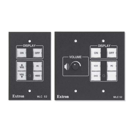
im Vertrieb von CAMBOARD Electronics If you want to remove any buttons from the switch group in order for them to operate independently, you must use the Windows-based control software. (See Using the MLC 52 Configuration Program in chapter 5, Serial Communication, for the process.) Front panel components The diagrams below show the front panel features of the standard one-gang sized... -
Page 30: Configuring The Mlc 52 Using Ir
im Vertrieb von CAMBOARD Electronics Operation, cont’d The protocol for this configuration port is as follows: • 9600 bits/second • 8 data bits • 1 stop bit • No parity Ring Sleeve (Gnd) 9-pin D Connection TRS Plug Pin 2 Computer's RX line Pin 3 Computer's TX line... - Page 31 im Vertrieb von CAMBOARD Electronics The following transfers are allowed: • From an RS model to another RS model • From an IR model to another IR model • From an IR model to an RS model To transmit configuration data via IR, both the transferring and the receiving MLCs must be free of the wall, electrical box, or furniture, and both must be powered on.
- Page 32 im Vertrieb von CAMBOARD Electronics Operation, cont’d The data transfer begins when the receiving unit detects the transmitting unit, and the process takes 15 to 20 seconds to complete. (It may take longer if the transmitting unit has multiple commands programmed on each button.) The front panel buttons act as data transfer progress indicators.
-
Page 33: Configuring Using Ir Learning
im Vertrieb von CAMBOARD Electronics If the transmission is interrupted (for example, the two units become separated so that the IR LEDs are no longer in direct line of sight of each other), and the conditions necessary for transfer are then restored, the two units restart the transfer process. -
Page 34: Removing Commands From A Button
im Vertrieb von CAMBOARD Electronics Operation, cont’d Point the projector’s remote control at the IR Transmit/Receive LEDs on the MLC, and press the button on the remote whose function you want the selected MLC button to learn. When the IR command has been learned successfully, the IR Learning LEDs blink in rapid progression from the top to the bottom, then back to the top. -
Page 35: Configuring A Single Button For Input Source Selection
im Vertrieb von CAMBOARD Electronics To program a macro on a button, follow these steps: Ensure that power is applied to the MLC 52. Set configuration switch #1 on the rear panel to On. All front panel buttons light dimly. Program the buttons with the desired commands. -
Page 36: Using The Mlc 52 Vc Models With The Mpa Series Power Amplifiers
im Vertrieb von CAMBOARD Electronics Operation, cont’d Repeat the procedure described in steps 5 and 6 for additional commands you want to add to the button you are programming. Each MLC button can be programmed with up to four commands. When finished programming the input selection button, set rear panel DIP switch #1 to Off. -
Page 37: Wiring And Connections For The Mlc 52 Vc Models
im Vertrieb von CAMBOARD Electronics • The projector must have a switched audio output. On most projectors, this connector is labeled as “Monitor Output” or “Audio Output,” as shown in the following illustration. With a switched audio output, the projector outputs the audio from the selected video source. -
Page 38: Powering The Projector/Display On And Off
im Vertrieb von CAMBOARD Electronics Operation, cont’d Powering the Projector/display On and Off The Display ON and OFF buttons on the MLC 52 front panel are used to turn the projector or other display on and off. Powering on Press and release the MLC 52’s ON button to turn the display device’s power on. The MLC sends an RS-232 or IR power-on command to the projector, and the ON button blinks for 4 seconds, then remains steadily lit. -
Page 39: Operating The Mlc 52 Using Ir Remote Control
im Vertrieb von CAMBOARD Electronics To select an input, press and release the appropriate input selection button. The command that was programmed in the button’s first memory block is executed. • All buttons are lit at 25% intensity while the MLC receives power. A selected (active) input button lights more brightly than those of the other inputs. -
Page 40: Buttons On The Ir 452 Remote Control
im Vertrieb von CAMBOARD Electronics Operation, cont’d To operate a device using the IR 452, point the remote control directly at the IR Link’s signal pickup window. The IR 452 has a range of approximately 30' (12 m) within 40 degrees on either side of the axis (see the illustration on the previous page). -
Page 41: Resetting
im Vertrieb von CAMBOARD Electronics Resetting In the event that the MLC 52 needs to be reset, you can do so by one of the following methods: Factory firmware reset — Press and hold the VIDEO button (on standard models) or the blank button (on VC models) while applying power to the MLC. - Page 42 im Vertrieb von CAMBOARD Electronics Operation, cont’d www.camboard.de Tel. 07131 911201 ce-info@camboard.de 3-16 MLC 52 Series MediaLink Controller • Operation Fax 07131 911203...
-
Page 43: Chapter 4 • Special Applications
im Vertrieb von CAMBOARD Electronics ™ MLC 52 Series MediaLink Controllers Chapter Four Special Applications Application 1: Using Multiple Sources with an MLC 52 Application 2: Projector Requiring a Power Off Confirmation Application 3: Controlling Projectors That Have Multi-Coded IR Functionality www.camboard.de Tel. -
Page 44: Application 1: Using Multiple Sources With An Mlc 52
im Vertrieb von CAMBOARD Electronics Special Applications This chapter describes some special types of applications that represent unique conditions. For the MLC 52 to operate properly in these situations, it is important that the controller be configured correctly. On the following pages, three application examples are described, along with their requirements for the MLC 52. -
Page 45: Configuring The Mlc 52 For Multiple Input Selection
im Vertrieb von CAMBOARD Electronics INPUTS RGB1 S-Video VIDEO RGB2 INPUTS S-Video RGB1 VIDEO RGB2 POWER PRG+ PLAY TIME/ TIME/ LEVEL– DLY/CNT/REAR LEVEL+ COMPUTER VIDEO PAUSE LEFT RIGHT COMPUTER VIDEO STOP DOWN PRG– – SKIP/CHAPTER VIDEO AUDIO DIR A MUTE MUTE MUTE INPUT... -
Page 46: Projector Remote Control Type A (Application 1)
im Vertrieb von CAMBOARD Electronics Special Applications, cont’d Projector remote control type A (application 1) This remote control has a discrete button for each input. Two buttons are designated for RGB inputs, one for S-video, and one for video (composite). •... -
Page 47: Projector Remote Control Type B (Application 1)
im Vertrieb von CAMBOARD Electronics If you are using an MLC 52 IR VC or an MLC 52 RS VC (two-gang models) with a remote type A, configure the buttons using the following scheme: INPUTS RGB1 S-Video VIDEO RGB2 POWER PRG+ PLAY TIME/... -
Page 48: Configuring Buttons For Multiple Inputs On An Rs-232 Controlled System
im Vertrieb von CAMBOARD Electronics Special Applications, cont’d COMPUTER VIDEO VIDEO AUDIO PROJECTOR MUTE MUTE MUTE MENU ENTER Command #1 Computer VIDEO Command #2 Video CONT/ COL/ SIZE CENTER TINT ASPECT SHARP PHASE RATIO MLC 52 Projector Remote Control Type B Programming MLC 52 input selection buttons from projector remote type B If you are using an MLC 52 IR VC or an MLC 52 RS VC with a type B remote... -
Page 49: Application 2: Projector Requiring A Power Off Confirmation
im Vertrieb von CAMBOARD Electronics Application 2: Projector Requiring a Power Off Confirmation Some projectors controlled via IR require the Power Off button on the hand-held remote control to be pressed twice to turn off the projector. These projectors usually present a prompt (similar to the one shown below) on the image, instructing you to press the Power Off button again to confirm your intent to power off the projector. -
Page 50: Application 3: Controlling Projectors That Have Multi-Coded Ir Functionality
im Vertrieb von CAMBOARD Electronics Special Applications, cont’d Put the MLC’s OFF button that you have just programmed into macro mode by pressing and holding the button for 3 seconds. The orange LED, labeled E on the back panel, flashes rapidly five times, then turns off, indicating that the button is now configured for macro mode. -
Page 51: Programming Video Inputs - Type A Remote Control
im Vertrieb von CAMBOARD Electronics When a command has been successfully learned, the IR Learning LEDs on the MLC rear panel flash in rapid progression from the top to the bottom, then back to the top. Program the input selection command “A” from the RGB 2 input selection button on the projector’s remote control into memory block #2 of the MLC 52’s PC button as follows: Press the PC button on the MLC front panel. - Page 52 im Vertrieb von CAMBOARD Electronics Special Applications, cont’d Within 5 seconds (while the VIDEO button on the MLC 52 is blinking), press the Video button on the projector’s remote control. The MLC has learned command “A” for video. When a command has been successfully learned, the IR Learning LEDs on the MLC rear panel flash in rapid progression from the top to the bottom, then back to the top.
-
Page 53: Issuing Input Selection Commands Learned From Remote Control Type A
im Vertrieb von CAMBOARD Electronics INPUTS RGB1 S-Video RGB2 VIDEO POWER PRG+ PLAY TIME/ TIME/ LEVEL– DLY/CNT/REAR LEVEL+ PAUSE DISPLAY LEFT RIGHT STOP DOWN PRG– – SKIP/CHAPTER Command #1 / RGB 1 / IR Command “A” DIR A INPUT Command #2 / RGB 2 / IR Command “A” +100 Command #3 / RGB 1 / IR Command “B”... -
Page 54: Configuring Vc Models - Type A Remote Control
im Vertrieb von CAMBOARD Electronics Special Applications, cont’d Configuring VC models — type A remote control If you are using an MLC 52 IR VC or an MLC 52 RS VC with a type A remote, configure the buttons as indicated in the illustration below. INPUTS S-Video RGB1... -
Page 55: Programming Video Inputs - Type B Remote Control
im Vertrieb von CAMBOARD Electronics Program the input selection command “B” from the RGB input selection button on the projector’s remote control into memory block #2 of the MLC 52’s PC button as follows: Press the PC button on the MLC front panel. The button begins to blink, indicating that the MLC is now ready to learn command “B”... -
Page 56: Issuing Input Selection Commands Learned From Remote Control Type B
im Vertrieb von CAMBOARD Electronics Special Applications, cont’d When finished programming the MLC 52 buttons, return configuration switch #1 to its off (down) position. Test the system. COMPUTER VIDEO VIDEO AUDIO MUTE MUTE MUTE DISPLAY MENU ENTER Command #1 / RGB / IR Command “A” Command #2 / RGB / IR Command “B”... -
Page 57: Configuring Vc Models - Type B Remote Control
im Vertrieb von CAMBOARD Electronics Configuring VC models — type B remote control If you are using a type B remote with an MLC 52 IR VC or an MLC 52 RS VC, configure the buttons according to the diagram below. COMPUTER VIDEO VIDEO... - Page 58 im Vertrieb von CAMBOARD Electronics Special Applications, cont’d www.camboard.de Tel. 07131 911201 ce-info@camboard.de 4-16 MLC 52 Series MediaLink Controller • Special Applications Fax 07131 911203...
-
Page 59: Chapter 5 • Serial Communication
im Vertrieb von CAMBOARD Electronics ™ MLC 52 Series MediaLink Controller Chapter Five Serial Communication Using the MLC 52 Configuration Program Using Simple Instruction Set (SIS ™ ) commands www.camboard.de Tel. 07131 911201 ce-info@camboard.de Fax 07131 911203... -
Page 60: Using The Mlc 52 Configuration Program
im Vertrieb von CAMBOARD Electronics Serial Communication The MLC 52 can be remotely configured via a host computer connected to the front panel configuration port. Through this port, you can program the MLC’s ® buttons with commands by using the Windows -based configuration software (MLC 52 Configuration program) or SIS ™... -
Page 61: Installing The Software
Access the program from the Start menu on your PC: Click Start on your PC screen. Select All Programs from the Start menu. From the Programs menu, select Extron Electronics. From the Extron menu, select MLC 52 + DVCM 50 Select MLC 52 Control Program. -
Page 62: Overview Of The Mlc 52 Configuration Program Screen
im Vertrieb von CAMBOARD Electronics Serial Communication, cont’d Click OK. After a few seconds, the Extron MLC 52 Configuration program screen appears, displaying the Controller (MLC) Config. tab. Overview of the MLC 52 configuration program screen The MLC 52 Configuration program screen The MLC 52 configuration program main screen contains the following: •... -
Page 63: Using The Help Program
im Vertrieb von CAMBOARD Electronics • Exit Program button: Click this button to exit the MLC 52 Configuration program and close the main screen. Using the Help program For information on program features, do one of the following to display the context-sensitive MLC 52 online Help: •... -
Page 64: Viewing Rs-232 Drivers
im Vertrieb von CAMBOARD Electronics Serial Communication, cont’d Viewing RS-232 drivers To view the settings and commands in each projector driver file without loading the driver into the MLC, run the MLC 52 control software in emulation mode. See Using emulation mode, later in this chapter. Open the MLC 52 configuration program. -
Page 65: Configuring The Controller
im Vertrieb von CAMBOARD Electronics Configuring the controller The Controller (MLC) Config. tab, shown below, is where you configure the controller and initiate IR Learning through software. This tab lets you perform IR Learning of commands to MLC button memory blocks, pick and assign IR or RS-232 driver functions to memory blocks, remove programming from buttons, and group buttons to operate in a mutually exclusive operation (switch pattern). -
Page 66: Saving And Restoring The Configuration
im Vertrieb von CAMBOARD Electronics Serial Communication, cont’d In the upper-right corner of the screen is the Macro... button. Clicking this button displays the MediaLink Macro Configuration window, which lets you link an MLC button with another button, so that pressing the first button once executes its commands, then those of the button to which it is linked. -
Page 67: Restoring A Configuration
im Vertrieb von CAMBOARD Electronics Save Current MediaLink Configuration as... window. Click Save. The current configuration is saved as a file with a .mlk extension. Restoring a configuration Restoring a configuration allows the software to quickly program an MLC 52 from an existing configuration. -
Page 68: Assigning Functions To Buttons Using Ir Drivers
im Vertrieb von CAMBOARD Electronics Serial Communication, cont’d Assigning functions to buttons using IR drivers Two types of drivers can be used to configure the MLC 52: IR and RS-232. This section discusses programming buttons using the IR drivers. Follow these steps to configure the MLC’s buttons with IR commands on the Controller (MLC) Config. - Page 69 im Vertrieb von CAMBOARD Electronics Pick IR Driver Functions button on Controller (MLC) Config. tab The Driver Selection window is displayed on top of the Controller (MLC) Config. tab. In the Driver Selection window, make selections in the following list boxes: Driver Category —...
- Page 70 im Vertrieb von CAMBOARD Electronics Serial Communication, cont’d Click the Take Button Config button to implement your selections. The command is programmed into the button’s selected memory block. • On the Driver Selection window, the radio button for the command memory block you just programmed is surrounded by a red field.
-
Page 71: Assigning Functions To Buttons Using Rs-232 Drivers
im Vertrieb von CAMBOARD Electronics Assigning functions to buttons using RS-232 drivers To assign button functions using RS-232 drivers, you must first load the drivers to the MLC 52 from the MediaLink file on your PC hard drive. Loading Extron drivers for RS-232 communication To load an Extron driver, follow these steps: From the File menu on the MLC 52 Configuration program screen, select Load New EXTRON DRIVER from... - Page 72 im Vertrieb von CAMBOARD Electronics Serial Communication, cont’d “Build MediaLink Configuration from...” window, drivers folder From the list on the “Build MediaLink Configuration from...” screen, select the driver for your projector, then click Open. Another confirmation prompt appears, reminding you that any previous settings will be overwritten by the new driver you are loading, and asking if you want to continue.
-
Page 73: Configuring Buttons Using Rs-232 Drivers
im Vertrieb von CAMBOARD Electronics Configuring buttons using RS-232 drivers After you have selected and loaded an RS-232 driver, you are ready to assign commands from the selected driver onto the MLC buttons. Follow these steps to configure the MLC’s buttons with RS-232 commands on the Controller (MLC) Config. - Page 74 im Vertrieb von CAMBOARD Electronics Serial Communication, cont’d Click the Pick 232 Driver Functs button, circled in the following illustration. Pick 232 Driver Functs button on Controller (MLC) Config. tab The Driver Selection window for RS-232 is displayed over the Controller (MLC) Config.
- Page 75 im Vertrieb von CAMBOARD Electronics Driver Selection window showing that memory block 1 (Cmd 1) contains an RS-232 (green) command • On the MLC diagram, the circle representing the memory block that you just programmed on the selected button appears green. MLC diagram showing an RS-232 command programmed on the PC button If you want to assign another command to the same button, select the next...
-
Page 76: Removing Commands From A Button
im Vertrieb von CAMBOARD Electronics Serial Communication, cont’d Removing commands from a button You can remove either one command from a button, or all the button’s commands at once. Select the button from which you want to remove commands. The button becomes yellow. -
Page 77: Setting Up Projector Volume Control
im Vertrieb von CAMBOARD Electronics Setting up projector volume control The MLC 52 can control the audio volume adjustment of the projector or plasma. By default, the two buttons labeled VOL UP and VOL DWN are configured to increase and decrease projector volume. When the Use for VOLUME control check box is selected, these two buttons control the projector’s volume. -
Page 78: Reprogramming The Volume Control Buttons
im Vertrieb von CAMBOARD Electronics Serial Communication, cont’d MLC 52 diagram on Controller tab, showing volume table enabled Reprogramming the volume control buttons If you do not want to use these two buttons for volume control — for example, if you have the MLC 52 IR VC or the MLC 52 RS VC, which have volume control knobs, you can reprogram them for other functions. -
Page 79: Grouping Buttons
im Vertrieb von CAMBOARD Electronics Grouping buttons Buttons can be grouped together so that they operate in a mutually exclusive (switch) group; that is, when one button is pressed, all others in its group are deselected. The active button lights brightly; the inactive button(s) are dimmed. You can group together any of the front panel buttons, except the Projector ON and OFF buttons, in any combination. -
Page 80: Linking Buttons To Create Macros
im Vertrieb von CAMBOARD Electronics Serial Communication, cont’d To place a button in macro mode, follow these steps: On the MLC 52 diagram, click the button that you want to configure. The button becomes yellow. Program onto the selected button the commands that you want to be part of the macro. -
Page 81: The Medialink Macro Configuration Screen
im Vertrieb von CAMBOARD Electronics The MediaLink MACRO Configuration screen MediaLink MACRO Configuration screen (no links established) The MediaLink MACRO Configuration screen is divided into two sections: • Trigger: The buttons in this section represent the button that you press on the MLC to issue the commands from both the linked buttons’... - Page 82 im Vertrieb von CAMBOARD Electronics Serial Communication, cont’d Select any of the command memory block buttons in the Trigger section (left side) that contains a command (i.e., is red or green). Hold the mouse button down as you drag the trigger button across the screen to the desired memory block button in the Destination section (right side), then release it.
-
Page 83: Linking Buttons In Macro Mode
im Vertrieb von CAMBOARD Electronics Linked buttons can be identified by their lighter shade of red or green, and by the destination button number displayed on the linked trigger and destination buttons. In the example above, pressing the MLC’s projector ON button also selects the VIDEO button command number. -
Page 84: Programming The Mlc 52 For Control By The Ir 452 Remote
im Vertrieb von CAMBOARD Electronics Serial Communication, cont’d When the ON button is pressed, the VIDEO button command 1 is issued, then the PC button command 1. If a daisy chain of button ties has been set up, pressing a linked button causes commands to be sent out for only the links made from the pressed button to subsequent buttons in the daisy chain. - Page 85 im Vertrieb von CAMBOARD Electronics Mute On button selected on IR 452 diagram When you select the button, the following also occurs on the screen: • The Button field in the upper-left corner of the tab displays IR 452, followed by the name/function of the button that was selected. In the previous example, this field contains “IR452-DISPLAY MUTE.”...
- Page 86 im Vertrieb von CAMBOARD Electronics Serial Communication, cont’d The Driver Selection window is displayed on top of the Controller (MLC) Config. tab. On the Driver Selection window, make selections in the following list boxes: Driver Category — Type of product to be controlled (Video Projector, Web TV, etc.) Device Models —...
- Page 87 im Vertrieb von CAMBOARD Electronics When finished programming commands to the button, click Close to close the Driver Selection window. On the Controller Config. (MLC) tab, the following is displayed: • At the top of the tab, the radio button for the command memory block you just programmed is surrounded by a red field (for an IR command) or a green field (for an RS-232 command).
-
Page 88: Removing Commands From An Ir 452 Button
im Vertrieb von CAMBOARD Electronics Serial Communication, cont’d Removing commands from an IR 452 button You can remove either one command from an IR 452 button, or all the button’s commands at once. Similar to the MLC 52 front panel buttons, removing commands one at a time is allowed only in descending order. - Page 89 im Vertrieb von CAMBOARD Electronics Learn IR to Button on the Controller (MLC) Config. tab If you have not set Configuration Switch #1 to On (step 1), the following dialog box opens, prompting you to do so. Flip the switch, then click OK. The following dialog box opens, indicating the button to which IR codes will be learned, and to allow you to OK or cancel the IR learning process.
-
Page 90: Using The Advanced Projector Config. Tab
im Vertrieb von CAMBOARD Electronics Serial Communication, cont’d Status of IR Learning field with instructions to aim remote control and press button Hold the projector ’s remote control 4" to 14" (10 cm to 36 cm) away from and directly facing the MLC’s IR Learning LEDs. (You may need to experiment to determine the best IR learning distance for each remote control.) Press the desired button on the projector remote within 5 seconds. - Page 91 im Vertrieb von CAMBOARD Electronics For additional details on using the features of the Advanced Projector Config. tab, refer to the MLC 52 Help file. Advanced Projector Config. tab example To view and program RS-232 commands to the MLC buttons using the Advanced Projector Config.
- Page 92 im Vertrieb von CAMBOARD Electronics Serial Communication, cont’d • If the selected MLC button currently contains no commands, the None radio button in the Sends field is filled. Select the RS-232 radio button to add commands to the button. • If the MLC button already contains commands, the Sends radio button for the command type on the button is filled.
-
Page 93: Creating A Volume Table
im Vertrieb von CAMBOARD Electronics When finished entering commands for the selected button, click the Take button in the lower-right corner of the screen to send the commands to the MLC. Take button on Advanced Projector Config. tab If you want to program any additional buttons, follow steps 1 through 6 for each button you want to configure. - Page 94 im Vertrieb von CAMBOARD Electronics Serial Communication, cont’d Follow these procedures to set up a new volume table: Click the Volume Table button in the top section of the Advanced Projector Config. tab. The volume table slide bars and buttons are displayed. Volume Table fields on Advanced Projector Config.
- Page 95 im Vertrieb von CAMBOARD Electronics Each volume adjustment step is a separate command, for which you enter text for each byte. Enter the text for the first byte of your Step 1 command in either the HEX or the ASCII small text box (located above the large HEX and ASCII fields).
-
Page 96: Buttons For The Ir 452-Accessible Functions
im Vertrieb von CAMBOARD Electronics Serial Communication, cont’d In the example below, the ninth byte was changed from F3 to E7 for Step 2, and two more bytes were added (00 and 16). Note that the Bytes field was set to 11. These are the only difference between volume Steps 1 and 2. -
Page 97: Misc. Options Tab
im Vertrieb von CAMBOARD Electronics Misc. Options tab The Misc. Options tab, shown below, includes an assortment of settings, including those pertaining to the projector, audio volume, and resetting the memories to factory defaults. Misc. Options tab When you make a change to an item on the Misc. Options tab, the Exit Program button in the lower-right corner of the screen is replaced by the Cancel and Take buttons. -
Page 98: Using Emulation Mode
im Vertrieb von CAMBOARD Electronics Serial Communication, cont’d Projector Volume Options — • Rate refers to the speed at which volume control commands are sent to the projector or plasma. The fastest command-sending rate is 0, the slowest is 3. •... - Page 99 im Vertrieb von CAMBOARD Electronics Comm Port Selection screen The Initialize Emulated MediaLink Configuration from... dialog box opens. You can create a new configuration starting from the default settings), or you can base the configuration on an existing setup. • If you will be creating a brand new configuration, click Cancel on the Initialize Emulated MediaLink Configuration from...
- Page 100 im Vertrieb von CAMBOARD Electronics Serial Communication, cont’d The Save Emulated MediaLink Configuration as... dialog box opens. Enter a filename of your choice for storing the configuration settings (it must have a .mlk extension), then click Save. The MediaLink EMULATION MODE Configuration dialog box appears, as shown below.
-
Page 101: Uploading Firmware
im Vertrieb von CAMBOARD Electronics MLC 52 Configuration program screen in emulation mode Select the desired settings in each section of the program to configure the buttons using the same processes described under Assigning functions to buttons using IR drivers and Assigning functions to buttons using RS-232 drivers, earlier in this chapter. - Page 102 im Vertrieb von CAMBOARD Electronics Serial Communication, cont’d The following window opens: Extron’s Firmware Loader window Click Upload. The following prompt opens. Click OK. Firmware Update file selection prompt On the Upload File from... window, locate and select the new firmware file. Firmware files are extracted to the following location: c:\Program Files\Extron\Firmware\MLC 52\####vxxx.s19 where # is an alphanumeric character and xxx is the firmware version...
-
Page 103: Using Simple Instruction Set (Sis ) Commands
MLC responds by sending a message to the host. No response is required from the host. The MLC-initiated messages are listed here (underlined). (C) Copyright 2005, Extron Electronics MLC 52, V1.00 The MLC sends the copyright message when it first powers on. Error responses When the MLC receives a valid SIS command, it executes the command and sends a response to the host device. -
Page 104: Symbol Definitions
im Vertrieb von CAMBOARD Electronics Serial Communication, cont’d The ASCII to HEX conversion table below is for use with the command/response tables. ASCII to HEX Conversion Table • ASCII to Hex conversion table Symbol definitions = CR/LF (carriage return/line feed) (hex 0D 0A). = CR (carriage return only) (hex 0D). - Page 105 im Vertrieb von CAMBOARD Electronics www.camboard.de Tel. 07131 911201 ce-info@camboard.de MLC 52 Series MediaLink Controller • Serial Communication 5-47 Fax 07131 911203...
-
Page 106: Command/Response Table For Advanced Instructions (For The Mlc 52 Configuration Program)
im Vertrieb von CAMBOARD Electronics Serial Communication, cont’d Command/response table for advanced instructions (for the MLC 52 configuration program) Data downloads and uploads are initiated by sending a series of hexadecimal commands to the configuration port of the MLC. The Windows-based control software uses these commands mainly to load and save driver data and system configuration settings. -
Page 107: Appendix A • Specifications, Part Numbers, And Accessories
im Vertrieb von CAMBOARD Electronics ™ MLC 52 Series MediaLink Controller A ppendix A Specifications, Part Numbers, and Accessories Specifications Part Numbers and Accessories www.camboard.de Tel. 07131 911201 ce-info@camboard.de Fax 07131 911203... - Page 108 im Vertrieb von CAMBOARD Electronics Specifications, Part Numbers, and Accessories Specifications Control/remote — MLC controller host ports Serial control port ......1 front panel 2.5 mm mini stereo jack (tip-ring-sleeve) Baud rate and protocol ....9600 baud, 8 data bits, 1 stop bit, no parity Serial control pin configurations Mini stereo jack: tip = TX, ring = RX, sleeve = GND Program control ......
-
Page 109: Included Parts
im Vertrieb von CAMBOARD Electronics Product weight MLC 52 RS, MLC 52 IR ... 0.2 lb (0.1 kg) MLC 52 RS VC, MLC 52 IR VC 0.3 lb (0.1 kg) Shipping weight ......3 lbs (2 kg) Vibration ........ISTA 1A in carton (International Safe Transit Association) Listings .......... -
Page 110: Accessories
im Vertrieb von CAMBOARD Electronics Specifications, Part Numbers, and Accessories, cont’d Accessories These items can be ordered separately: Mounting hardware Part number One-gang EWB external wall box (black, white) 60-452-02, -03 One-gang junction box, 2.5” deep 980130 One-gang SMB surface mount box (black only) 60-639-02 Two-gang EWB external wall box (black, white) 60-453-02, -03... -
Page 111: Cables
im Vertrieb von CAMBOARD Electronics Cables This cable is recommended for connecting an MLC to an IR Link. Comm-link cable Part number 50 feet/15.2 meters long 26-461-01 100 feet/30.5 meters long 26-461-02 200 feet/61 meters long 26-461-03 400 feet/122 meters long 26-461-04 Bulk 500 feet/152.4 meters long, plenum 22-119-02... - Page 112 im Vertrieb von CAMBOARD Electronics Specifications, Part Numbers, and Accessories, cont’d www.camboard.de Tel. 07131 911201 ce-info@camboard.de MLC 52 Series MediaLink Controller • Specifications, Part Numbers, and Accessories Fax 07131 911203...
-
Page 113: Appendix B • Dimensions And Templates
im Vertrieb von CAMBOARD Electronics ™ MLC 52 Series MediaLink Controller A ppendix B Dimensions and Templates Dimensions Templates www.camboard.de Tel. 07131 911201 ce-info@camboard.de Fax 07131 911203... -
Page 114: Dimensions
im Vertrieb von CAMBOARD Electronics Dimensions and Templates Dimensions The following diagrams have been reduced to fit on the page. All dimensions are given in inches. The symbol “ø“ indicates a diameter. Standard MLC 52 IR and MLC 52 RS (one-gang size) 85°... -
Page 115: Mlc 52 Ir Vc And Mlc 52 Rs Vc (Two-Gang Size
im Vertrieb von CAMBOARD Electronics MLC 52 IR VC and MLC 52 RS VC (two-gang size) 4.500 .156 THRU Ø.500 .295 X 82° 2X 3.891 2X 3.423 3.313 3.192 Ø.178 THRU 2X 2.803 2X 2.548 2.238 2.062 .125 THRU .240 X 82° 1.613 2X 1.303 2X 1.088... -
Page 116: Templates
im Vertrieb von CAMBOARD Electronics Dimensions and Templates, cont’d Templates Use the rough-in templates in this chapter as guides to measure and mark the hole in the wall or furniture through which the MLC 52 will be mounted. The templates provide measurements for installing the controller with either an electrical box or a mounting bracket. - Page 117 im Vertrieb von CAMBOARD Electronics Cut-Out Template for Extron's MLC 52 VC (Front view) 4.60" (11.68 cm) Top Panel 2.91" 4.50" (7.40 cm) (11.43 cm) SURFACE CUT-OUT AREA FOR FURNITURE MOUNT Location of MLC 52 To install MLC 52 VC directly into furniture or wall, cut along this line.
- Page 118 im Vertrieb von CAMBOARD Electronics Dimensions and Templates, cont’d www.camboard.de Tel. 07131 911201 ce-info@camboard.de MLC 52 Series MediaLink Controller • Dimensions and Templates Fax 07131 911203...
- Page 119 Extron’s Warranty Extron Electronics warrants this product against defects in materials and workmanship for a period of three years from the date of purchase. In the event of malfunction during the warranty period...
- Page 120 3821 AH Amersfoort PM Industrial Building Singapore 368363 Chiyoda-ku, Tokyo 102-0082 Japan The Netherlands +81.3.3511.7655 714.491.1500 +31.33.453.4040 +65.6383.4400 Fax +81.3.3511.7656 www.extron.com Fax 714.491.1517 Fax +31.33.453.4050 Fax +65.6383.4664 www.camboard.de Tel. 07131 911201 ce-info@camboard.de © 2006 Extron Electronics. All rights reserved. Fax 07131 911203...
Need help?
Do you have a question about the MediaLink MLC 52 IR and is the answer not in the manual?
Questions and answers