
Related Manuals for Kongskilde FC 860


Summary of Contents for Kongskilde FC 860
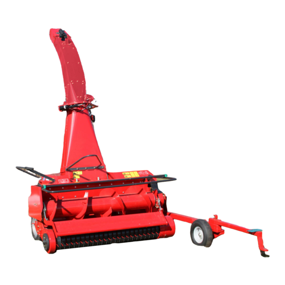
- Page 1 ORIGINAL INSTRUCTIONS - according to Directive 2006/42/EC, Annex I 1.7.4.1 OPERATOR’S MANUAL FC 860 Harvester Part number 81PIGB-204x edition English February 2018...
-
Page 3: Foreword
DEAR CUSTOMER! We appreciate the confidence you have shown to our company by investing in a KONGSKILDE product and congratulate you on your new purchase. Of course, it is our wish that you will experience complete satisfaction with the purchase investment. -
Page 4: Table Of Contents
MOUNTING OF LIFT SUSPENSION ............... 29 CONNECTION AND DISCONNECTION OF PRECISION CHOPPER ..... 32 3. MOUNTING OF EQUIPMENT ..................34 HITCH FOR TRAILER ..................34 PICK-UP ......................36 CHUTE AND DEFLECTOR ................37 - 4 - PIGB-204X 03 FC 860 0218... - Page 5 8. STORAGE (WINTER STORAGE) ................. 70 10. SPARE PARTS ORDERING ..................71 11. DISPOSAL ........................72 12. FAULT FINDING ......................73 DIAGRAMS: ..................... 73 CONTROL SYSTEM ..................74 WIRING SYSTEM ..................... 75 13. WARRANTY ........................ 76 - 5 - PIGB-204X 03 FC 860 0218...
-
Page 6: Introduction
The machine should only be connected to a tractor which corresponds with the specifications of the product and is legal to use. Any use beyond this is outside the intended use. Kongskilde Industries A/S is not responsible for any damage or injury resulting from such use; the user bears that risk. -
Page 7: Performance
The FC 860 is capable of working alone or parallel with other machines. FC 860 has a high capacity compared with other corresponding products as it uses the “UPPER CUT” system. “UPPER CUT” gives a minimum loss of power when cutting the material and thus ensures maximum utilisation of the accessible tractor power. - Page 8 The power requirements are also increased when the blades are worn and the shear- bar clearance is increased. It is necessary to sharpen the blades and adjust the shearbar during the season. - 8 - PIGB-204X 03 FC 860 0218...
-
Page 9: Safety
1. INTRODUCTION SAFETY The safety of persons and machines is an integral part of Kongskilde’s development work. However, damage can occur as a consequence of misuse and insufficient instruction. We wish to ensure the safety of you and your workforce in the best possible way, but this also requires an effort on your part. -
Page 10: Definitions
DANGER: The word DANGER is used to indicate measures which, according to legislation, must be followed to protect the driver and others against serious injuries. - 10 - PIGB-204X 03 FC 860 0218... -
Page 11: General Safety Instructions
13. Always use hearing protectors if the noise from the machine is annoying or if you are working with the machine for a considerable period in a tractor cabin, which has not been silenced sufficiently. - 11 - PIGB-204X 03 FC 860 0218... - Page 12 19. Do not try to remove material from the cutting unit while it is working. 20. If material must be removed from the forage harvester, the PTO shaft must be disconnected completely. Stop the tractor engine before removing any material from the forage harvester. - 12 - PIGB-204X 03 FC 860 0218...
-
Page 13: Locking Of Guards
It is important that there is direct access to the 12-volt battery of the tractor and that it is in a good condition. Always choose a tractor with a closed cabin when working with a precision chopper. - 13 - PIGB-204X 03 FC 860 0218... -
Page 14: Connection And Disconnection
You should always protect the skin and the eyes against oil splashes (see fig. 1-4). If, by accident, hydraulic oil under pressure hits you, consult a doctor immediately. Fig. 1-4 - 14 - PIGB-204X 03 FC 860 0218... -
Page 15: Adjustment
When lifting the delivery chute above the blade cylinder make sure that nobody is in danger of being hit by the guard. When lifting the guard, hold on to the hoop which is fastened to the intermediate guard with both hands. - 15 - PIGB-204X 03 FC 860 0218... -
Page 16: Transport
The pick-up of the forage harvester must be secured mechanically before transport. The statutory lighting and traffic markings must be placed correctly, on the forage harvester as well as the trailer. Reflectors and lighting must be cleaned regularly. - 16 - PIGB-204X 03 FC 860 0218... -
Page 17: Working
Never try to clean, grease or adjust the machine before the PTO has been disengaged, the tractor engine has stopped and the parking brake been activated. Remove the ignition key! - 17 - PIGB-204X 03 FC 860 0218... -
Page 18: Grinding
Always use safety glasses when grinding as small particles from the grindstone might hit you. When grinding has finished, stop the tractor engine, change the direction of rotation and fasten all guards. REMEMBER: Only grind with all guards closed! - 18 - PIGB-204X 03 FC 860 0218... -
Page 19: Maintenance
This heat treatment provides especially hard and ductile material which is able to withstand extreme stress. Damaged blades, blade bolts or shear-bars must be replaced by original KONGSKILDE spare parts only to ensure safe operation. Blades and blade bolts must be checked every day during the season. - Page 20 1. INTRODUCTION - 20 - PIGB-204X 03 FC 860 0218...
-
Page 21: Safety Decals
Warning against hydraulic oil under pressure. The PTO drive shaft. This decal has the purpose to remind you how dangerous the PTO drive shaft can be if it is not correctly mounted or protected. - 21 - PIGB-204X 03 FC 860 0218... -
Page 22: Dimensions
1. INTRODUCTION DIMENSIONS 2452 4515 6521 - 22 - PIGB-204X 03 FC 860 0218... -
Page 23: Technical Data
Hitch for trailer: Maximum drawbar load 2000kg (*) Depends on dry matter content, cutting length, the conditions and the amount of crop. We reserve the right to change the construction and specification details without notice. - 23 - PIGB-204X 03 FC 860 0218... -
Page 24: Connection To Tractor
The machine requires 1 single-acting hydraulic outlet for the pick-up and 1 double- acting outlet for the hydraulic adjustable hitch, if mounted. Therefore the tractor should have 1 double-acting and 1 single-acting outlets to be able to drive with a fully equipped FC 860. - 24 - PIGB-204X 03 FC 860 0218... -
Page 25: Connection Of Electric System
Here the 7-pole plug from the machine must be connected. Important: When the machine is parked the 7-pole plug should be placed in the holder on the left-hand, rear guard. - 25 - PIGB-204X 03 FC 860 0218... -
Page 26: Electric Control
The machine is operated from the control box which controls the electric functions. FUNCTIONS Fig. 2-5 Fig. 2-5 On the joystick: Chute: Push to the left: The chute turns anti-clockwise. Push to the right: The chute turns clockwise. - 26 - PIGB-204X 03 FC 860 0218... - Page 27 Feed in: Move the toggle switch to the rear. When feed rollers and pick-up are running, the switch must be released. This may take about 5 seconds. Reverse: Move the toggle switch forward. Caution: Only reverse briefly and at reduced number of rpm. - 27 - PIGB-204X 03 FC 860 0218...
- Page 28 2. CONNECTION TO TRACTOR Fig. 2-8 Fig. 2-8 The position of the reverse can be checked on the indicator A. - 28 - PIGB-204X 03 FC 860 0218...
-
Page 29: Mounting Of Lift Suspension
The lift suspension is fitted with hitch hook as standard. For connection of trailers with clevis drawbar the drawbar is placed with the hitch hook facing forwards and the hole for clevis drawbar facing backwards. - 29 - PIGB-204X 03 FC 860 0218... - Page 30 Fig. 2-12 The length of the PTO shaft is adjusted so that it: in working position has minimum 200 mm overlap. In no position is compressed more than the prescribed 30 mm in order not to bottom the shaft. In the outmost position has minimum 200 mm overlap. - 30 - PIGB-204X 03 FC 860 0218...
- Page 31 Before starting a new machine, the clutch must be "aired". See section concerning the friction clutch in chapter 6 "MAINTENANCE". - 31 - PIGB-204X 03 FC 860 0218...
-
Page 32: Connection And Disconnection Of Precision Chopper
If the pawl cannot be released, the length of the wire must be checked. When driving away make sure the trailer comes clear of the precision chopper. Please note! The machine must be lowered to the ground before the locking pawl can be released. - 32 - PIGB-204X 03 FC 860 0218... - Page 33 Thereby it becomes easier to “pick up” the trailer from the ground without the precision chopper touching the ground. The big movement at the rear is obtained by mounting the top link low on the tractor and high on the suspension. - 33 - PIGB-204X 03 FC 860 0218...
-
Page 34: Mounting Of Equipment
For disconnection the cord for the hitch lock is pulled and the 3-point linkage frame is lowered until the support of the hitch is resting on the ground. Drive forward with the tractor and the precision chopper. - 34 - PIGB-204X 03 FC 860 0218... - Page 35 A or a firm hitch which is mounted on the 3-point suspension frame Fig. 3-4 Fig. 3-4 During transport on the public roads the stop valve C on the hydraulic hose for the cylinder must be closed. This prevents faulty operation during transport. - 35 - PIGB-204X 03 FC 860 0218...
-
Page 36: Pick-Up
Mount the 2 pins in order to fix the pick-up to the base machine. Attach the relief device to the pick-up at B. Fig. 3-6 Fig. 3-6 Mount the chain drive for the pick up and tension correctly. - 36 - PIGB-204X 03 FC 860 0218... -
Page 37: Chute And Deflector
Place the bracket A above the adjusting bar and assemble it, then mount and fasten the bracket B. Grease the swivel ring and check that the delivery chute can turn freely. IMPORTANT: Grease the swivel ring while turning the delivery chute manually to distribute the grease. - 37 - PIGB-204X 03 FC 860 0218... - Page 38 If the movements and the marking do not correspond, the wires in the assembly box on the motor(s) in question must be exchanged to alter the direction of movement. - 38 - PIGB-204X 03 FC 860 0218...
-
Page 39: Adjustments
You should keep the pick-up at such a height that the tines do not hit the ground and leave earth in the crop and can also pick up the grass without waste. KONGSKILDE recommends a distance between the pick-up tines and the ground of 15 to 20 mm. - Page 40 Fig. 4-4 Fig. 4-4 The adjustment is made at the opposite side at the hydraulic cylinder of the suspension. - 40 - PIGB-204X 03 FC 860 0218...
-
Page 41: Opening Of Rotor Housing
DANGER: First, make sure there are no other persons near the machine. Only fold down the chute when the machine is connected to a tractor. - 41 - PIGB-204X 03 FC 860 0218... - Page 42 Fig. 4-6 Fig. 4-6 2) Open the guard above the rotor housing and the right-hand guard. Fig. 4-7 Fig. 4-7 3) Open the lock clamps at the front of the rotor housing. - 42 - PIGB-204X 03 FC 860 0218...
- Page 43 5) When closing the rotor housing, follow the same procedure in reverse order. Fig. 4-9 Fig. 4-9 When closing the rotor housing it is an advantage to lift the chute at first. - 43 - PIGB-204X 03 FC 860 0218...
-
Page 44: Rotor And Roller Section
The distance between the scraper and the smooth roller should be maximum 0.5 mm. Tighten the bolts F with a torque wrench to 10-12 kgm (100-120 Nm). Wrong adjustment of the scraper may result in overheating of the smooth roller and operational stoppage. - 44 - PIGB-204X 03 FC 860 0218... - Page 45 Fig. 4-12 Fig. 4-12 The distance between the smooth roller and the serrated roller should be max. 3 mm. Adjustment is made with the bolts G at both sides of the rotor housing. - 45 - PIGB-204X 03 FC 860 0218...
- Page 46 However, when driving in a crop where there is an excessive waste under the rollers, the bottom plate must be mounted. - 46 - PIGB-204X 03 FC 860 0218...
-
Page 47: Cutting Lengths
Fig. 4-16 Fig. 4-16 2) Feed intake speed, which is changed by using the following sprocket wheels: Sprocket wheel No. Number of teeth Z 2064-448X 2064-449A 2065-460X 2064-450A 2064-451A 2062-442X - 47 - PIGB-204X 03 FC 860 0218... -
Page 48: Replacement And Adjustment Of Blades
Only use original blade bolts when replacing. Tighten the blade bolts with a torque wrench to 400 Nm (approx. 40 kpm) or with the supplied spanner using approx. 40 kg leverage (400 Nm). - 48 - PIGB-204X 03 FC 860 0218... - Page 49 Fig. 4-18 Fig. 4-18 When mounting new blades they must be pulled out so that the outer diameter on the rotor is 480 mm (from rotor tube to blade point = 178mm). - 49 - PIGB-204X 03 FC 860 0218...
- Page 50 4. ADJUSTMENTS Fig. 4-19 Fig. 4-19 When replacing blade bolts, it is important to ensure that the area A under the bolt heads is greased. - 50 - PIGB-204X 03 FC 860 0218...
-
Page 51: Grinding
Lift the guard above the grinding device. Fig. 4-20 Fig. 4-20 2. Lower the guard between the grinding device and the rotor so that there is free space between the device and the rotor. - 51 - PIGB-204X 03 FC 860 0218... - Page 52 PTO drive shaft must be fixed at position 2 whereby the rotor will rotate in the opposite direction. Close all guards. Start the tractor and keep the rpm at a little above idle speed. - 52 - PIGB-204X 03 FC 860 0218...
- Page 53 For safety's sake check the distance between blades and shear-bars again with the gauge. Check wear of the grindstone regularly. If the stone has been worn down to a thickness of 10 mm it must be replaced. - 53 - PIGB-204X 03 FC 860 0218...
-
Page 54: Rough Grinding
Be careful not to grind down the cutting edge (front edge) of the blades. WARNING: First, block the blade cylinder with a wooden wedge as the sharp blades can easily cause injury. Always use safety glasses when grinding. - 54 - PIGB-204X 03 FC 860 0218... -
Page 55: Reverse
IMPORTANT: If the tightening of the belt drive is not correct it can be because the bracket B which transmits the correct power from the electric motor is too tight or stuck. Disassemble the parts, clean, and grease the rocking mechanism before reassembling the parts. - 55 - PIGB-204X 03 FC 860 0218... -
Page 56: Driving In The Field
If it is possible to influence the swathing made before chopping it is important to emphasise that regular and even swaths are optimal for the subsequent chopping and will spare the tractor driver a lot of trouble. - 56 - PIGB-204X 03 FC 860 0218... -
Page 57: Transport Position
When driving on public roads, the delivery chute must be in a position where it does not increase the transport width of the machine. Fig. 5-3 Fig. 5-3 Make sure that the cylinder stop C is engaged before driving on public roads. - 57 - PIGB-204X 03 FC 860 0218... -
Page 58: Starting In The Field
Check regularly that the pick-up tines do not reach further down than necessary to be able to pick up the swath efficiently. If the tines hit the ground too hard they are quickly worn and the drive of the pick-up may be overloaded. - 58 - PIGB-204X 03 FC 860 0218... -
Page 59: Blockage In The Machine
After reversing move the reverse system back to normal feed intake at a low number of rpm. When the machine runs correctly, increase to correct number of rpm and the work can be continued. - 59 - PIGB-204X 03 FC 860 0218... - Page 60 After reversing disconnect the power take-off again and, when the feed intake has come to a complete stop, remove any grass residue and move the PTO shaft A for the rotor back to the pin B for driving the rotor. - 60 - PIGB-204X 03 FC 860 0218...
-
Page 61: Various
When the machine runs correctly, increase to correct number of rpm and the work can be continued. VARIOUS If you use ensiling agents, the safety instructions of these must be observed. It is very important to protect the eyes. - 61 - PIGB-204X 03 FC 860 0218... -
Page 62: Maintenance
[Nm] [Nm] [Nm] M 10 M 12 M 12x1,25 M 14 M 14x1,5 M 16 M 16x1,5 M 18 M 20 M 24 1100 M 24x1,5 1175 M 30 1300 1800 2300 - 62 - PIGB-204X 03 FC 860 0218... -
Page 63: Guards
Support wheel 500-8 Max. 2,4 bar Rubber wheels for pick-up (Optional 3.50-6/4 3,0 bar equipment) CAUTION: Check the tyre pressure regularly and make sure that the wheel- fixing bolts are tightened correctly. - 63 - PIGB-204X 03 FC 860 0218... -
Page 64: Friction Clutch
This especially applies after winter storage before the machine is used for the first time in the season. - 64 - PIGB-204X 03 FC 860 0218... - Page 65 The nuts are loosened again until they are at level with the threads of the bolts, and the springs can press on the clutch plates. - 65 - PIGB-204X 03 FC 860 0218...
-
Page 66: Fuse
The supplied electrical connection includes a 20A fuse. WARNING: Never mount fuses with a higher power value. The control system may be damaged. If fuses blow there is an error in the electric system. - 66 - PIGB-204X 03 FC 860 0218... -
Page 67: Various
It is turned in + direction for tightening and in – direction for loosening. CAUTION: It should always be possible to move the chain at least 20 mm up and down in the middle. - 67 - PIGB-204X 03 FC 860 0218... - Page 68 7. GREASING Daily lubrication Lubrication once a week 11 11 - 68 - PIGB-204X 03 FC 860 0218...
-
Page 69: Greasing
Support arm for pick-up Bevel gearbox: Oil type: Quality API GL4 or GL5 SAE 80W-90 Oil content: PTO 1000 PTO 540 Oil change: After the first 10 working hours and then anually. - 69 - PIGB-204X 03 FC 860 0218... -
Page 70: Storage (Winter Storage)
Spray the machine with a thin coat of rust-preventing oil. This is especially important on parts polished. Change the oil in the gearboxes. Store the machine in a ventilated building. Lay up the machine to unload the tyres. - 70 - PIGB-204X 03 FC 860 0218... -
Page 71: Spare Parts Ordering
Type: Year: ade for Kongskilde Industries A/S DK4180 www.kongskilde.com Maximum total weight: Maximum load axle 1:... -
Page 72: Disposal
Disassemble the machine and separate the individual parts, e.g. PTO drive shafts, tyres, hydraulic components etc. Hand over the usable parts to an authorised recycling centre. The large scrapping parts are handed over to an authorised breaker's yard. - 72 - PIGB-204X 03 FC 860 0218... -
Page 73: Fault Finding
12. FAULT FINDING 12. FAULT FINDING DIAGRAMS: The figures below show the electric diagrams for the machine. Here you can follow the wiring system between the components, for instance when maintaining or replacing cables. - 73 - PIGB-204X 03 FC 860 0218... -
Page 74: Control System
12. FAULT FINDING CONTROL SYSTEM - 74 - PIGB-204X 03 FC 860 0218... -
Page 75: Wiring System
Joystick sw 5.1 V5a Valve Joystick 6.4 Joystick Right V4A not used Joystick sw 5.2 V6 Valve Joystick 6.2 Joystick Down V3B Joystick 6.3 Joystick Left Joystick 6.1 Joystick Up - 75 - PIGB-204X 03 FC 860 0218... -
Page 76: Warranty
It is prohibited to carry out any modifications to the machine unless specifically authorized, in writing, by a NEW HOLLAND representative. PIGB-204X 03 FC 860 0218... - Page 77 Jiddikjaraw li / Apstiprinu, ka Maskine: La máquina: Masin: Maschine: Maszyna: Stroj: Машината: Η μηχανή: Machine: Machine: Gép: Máquina: Model/Type: FC 860 La macchina: Stroj: Il-magna: Mašina: Mašīna: Machine: Designation: Harvester Maskin: Stroj: Serial: Maşina: Laite: - er i overensstemmelse med Maskindirektivets bestemmelser (Direktiv 2006/42/EF) og hvis relevant også...
- Page 78 - est conforme aux dispositions de la Directive relatives aux machines 2006/42/CE et également aux dispositions de la Directive sur la Directive EMC 2014/30/UE. - é in conformita' con la Direttiva Macchine 2006/42/CE e, se pertinente, anche alla Direttiva alla Direttiva EMC 2014/30/UE.
- Page 80 Kongskilde dealer. © 2018 CNH Industrial Belgium N.V. All Rights Reserved. Kongskilde is a trademark registered in the United States and many other countries, owned by or licensed to CNH Industrial N.V., its subsidiaries or affiliates. Any trademarks referred to herein, in association with goods and/or services of companies, other than owned by or licensed to...
Need help?
Do you have a question about the FC 860 and is the answer not in the manual?
Questions and answers