
Related Manuals for Kongskilde Vibro Crop Series


Summary of Contents for Kongskilde Vibro Crop Series
- Page 1 ORIGINAL INSTRUCTIONS - according to Directive 2006/42/EC, Annex I 1.7.4.1 OPERATOR’S MANUAL Vibro Crop Vibro Crop Intelli Inter-Row Cultivator Part number 51601877 edition English May 2019...
-
Page 2: Table Of Contents
Contents 1 GENERAL INFORMATION Note to the owner................1-1 Intended use. - Page 3 Parking the unit Disconnection and parking ............. 4-7 5 TRANSPORT OPERATIONS Road transport Transport position .
- Page 4 Every six years Hydraulic hoses ............... 7-11 Storage Pressure washing .
-
Page 5: General Information
Directives 2006/42/EC and 2014/30/EU. Always use genuine KONGSKILDE Service Parts or parts that match at least the same quality, reliability and func- tionality as the equivalent original Service Parts when you service and repair your implement and do not modify your implement without a written permission of the manufacturer. - Page 6 KONGSKILDE is not liable for any damage caused by the use of ''non-genuine” parts and accessories. Rely on your authorized dealer to supply you with genuine KONGSKILDE parts only. These parts are covered by our warranty and will give you the best performance.
- Page 7 It is prohibited to carry out any modifications to the implement unless specifically authorized, in writing, by a KONGSKILDE representative. CLEANING YOUR IMPLEMENT When you use a high pressure washer, do not stand too close to the implement and avoid directing the jet at electronic components, electrical connections, breathers, seals, filler caps, and so on.
-
Page 8: Intended Use
• Ensure that each piece of non‐ KONGSKILDE equipment fitted to the machine bears the CE mark. • The maximum power of emission equipment (radio, telephones, etc.) must not exceed the limits imposed by the national authorities of the country where you use the machine. -
Page 9: Manual Scope And Required Training Level
KONGSKILDE during normal operation, routine service, and maintenance. Periodic service consists of activities that are necessary to maintain the expected life of the KONGSKILDE ma- This manual does not contain all the information that re- chine. These activities have defined intervals. -
Page 10: Product Identification Number (Pin)
The Product Identification Number (PIN) is a serial num- ber that identifies the implement. The serial number, model and other specifications are on the PIN plate. Provide your KONGSKILDE dealer with the model and the PIN when you order parts. ZEIL18HT00546EA Company name... -
Page 11: Product Identification
1 - GENERAL INFORMATION Product identification NOTE: Do not remove or change the Product Identifica- tion Number (PIN) plate (1) on the implement. The PIN plate (1) is on the front of the implement. ZEIL19TIL0205FA For future reference, record your implement model and PIN in the spaces below. -
Page 12: Implement Orientation
1 - GENERAL INFORMATION Implement orientation NOTE: To determine the left-hand side and the right-hand side of the implement, stand behind the implement and face the direction of travel during working operation. The following overhead view illustration is a general repre- sentation of the implement. -
Page 13: Implement Components
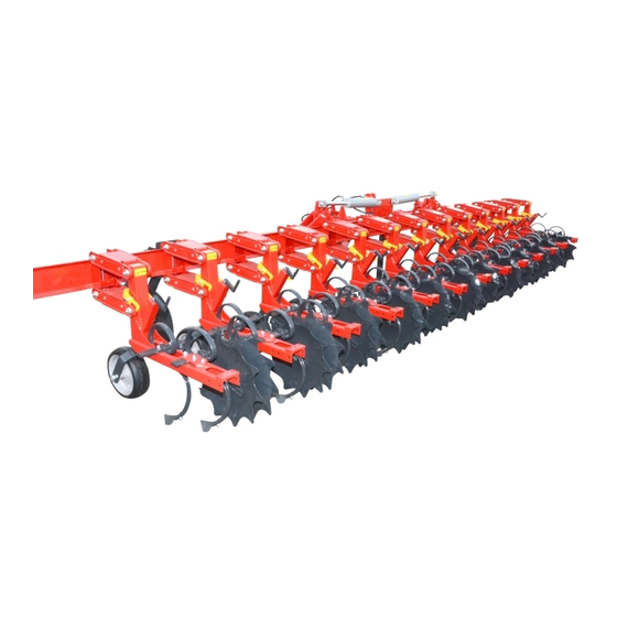
1 - GENERAL INFORMATION Implement components Vibro Crop Intelli ZEIL19TIL0205FA Standard equipment: Optional equipment: Support wheels Section control Working section Loading platform with steps Stabilizing disc FS SEEDER Parallelogram side shift frame (10) Rear harrow Parking legs (front and rear) Light set... - Page 14 1 - GENERAL INFORMATION Vibro Crop ZEIL19TIL0214FA Standard equipment: Optional equipment: Main frame Loading platform with steps Working section FS SEEDER Stabilizing disc Rear harrow Parallelogram side shift frame Parking legs (front and rear) Light set Structure of the working section Working section: Parallelogram Vibro S tine or Vibro Crop tine...
-
Page 15: Safety Information
2 - SAFETY INFORMATION 2 - SAFETY INFORMATION###_2_### Safety rules and signal word definitions Personal safety This is the safety alert symbol. It is used to alert you to potential personal injury hazards. Obey all safety messages that follow this symbol to avoid possible death or injury. Throughout this manual you will find the signal words DANGER, WARNING, and CAUTION followed by special in- structions. -
Page 16: General Recommendations
2 - SAFETY INFORMATION General recommendations Most farm machinery accidents can be avoided by the rized to use the implement. Never leave the implement observance of a few simple safety precautions. to others before you have made sure that they have the necessary knowledge to operate the implement safely. -
Page 17: Illustrations
2 - SAFETY INFORMATION Illustrations WARNING Illustrations in this manual may show protective shielding open or removed to better illustrate a par- ticular feature or adjustment. Replace all shields before operating the machine. Failure to comply could result in death or serious injury. W0012A NOTE: Some of the illustrations in this manual have been obtained by photographing prototypes. - Page 18 2 - SAFETY INFORMATION Hazardous chemicals 1. If you are exposed to or come in contact with haz- well as the information in this manual when you ser- ardous chemicals you can be seriously injured. vice the machine. The fluids, lubricants, paints, adhesives, coolant, 4.
-
Page 19: Traveling On Public Roads
2 - SAFETY INFORMATION Traveling on public roads Comply with the relevant traffic regulations Passengers WARNING Do not allow passengers to ride in the tractor unless a specific seat is provided. Impact hazard! Take care when making turns. The machine During transport, the transportation of people on the top rear end swings out when changing direction. - Page 20 2 - SAFETY INFORMATION When you turn during transport pay attention to the over- After you finish the transport, before you leave the tractor, hang and/or oscillating weight of the implement. always lower the implement to the ground in parking po- sition, turn off the tractor engine, pull the parking brake, Use engine braking when you drive down hills.
-
Page 21: Operating The Implement Safely
2 - SAFETY INFORMATION Operating the implement safely When you operate the implement, always remain seated in the tractor cab. Operate controls only when seated in WARNING the tractor seat, except for those controls expressly in- Hazard to bystanders! tended for use from other locations. Always sound the horn before starting the ma- chine. -
Page 22: Maintenance
2 - SAFETY INFORMATION Maintenance link arms of the tractor so that the implement cannot move to a lower position unintentionally. WARNING • Relieve the pressure, stop the engine and remove the Maintenance hazard! ignition key, before you connect or disconnect fluid Before you start servicing the machine, attach lines. -
Page 23: Personal Protective Equipment (Ppe)
2 - SAFETY INFORMATION Personal protective equipment (PPE) Wear Personal Protective Equipment (PPE) such as pro- tective clothing, eye protection, hearing protection, dust mask, hard hat, heavy gloves, work boots, and/or any other PPE that provides for the safety and protection of the individual that operates this equipment. -
Page 24: Noise Emission
2 - SAFETY INFORMATION Noise emission The measuring and reporting of the noise level were car- ried out according to EN ISO 3746: 2005. The measure- ment uncertainty is approximately +/- 2 dB. The noise emissions for the implement equipped with FS Seeder are: 1. -
Page 25: Implement Stability
2 - SAFETY INFORMATION Implement stability The combination of your tractor and implement can become unstable, due to the additional weight that the implement adds to the tractor. In order to guarantee stable and safe transport, you must check if you need ballast weights for transport and field work. -
Page 26: Ecology And The Environment
KONGSKILDE dealer, who will dispose of the used this legislation. Where no legislation exists, obtain in- batteries or recycle the used batteries properly. In some formation from suppliers of oils, filters, batteries, fuels, countries, this is a legal requirement. -
Page 27: Safety Signs
2 - SAFETY INFORMATION Safety signs The following safety signs are on your implement as a guide for your safety and for the safety of those who work with you. Walk around the implement and note the content and loca- tion of all safety signs before you operate your implement. - Page 28 2 - SAFETY INFORMATION ZEIL19TIL0205FA Safety sign (1) A hazard of falling caused by standing on the implement when working or in transport. The hazard could result in death or serious injury. Traveling on the implement or entering the implement when working is strictly prohibited.
- Page 29 2 - SAFETY INFORMATION Safety sign (3) Mount transport belts here. Part number: 74000666103 74000666103 Safety sign (4) Speed limit: 25km/h. Part number: 300008277 300008277 Safety sign (5) Keep hands away. Never move your hand into the danger zone as long as the parts can move.
- Page 30 2 - SAFETY INFORMATION Safety sign (6) Lubrication point. Part number: 74000667708 74000667708 Safety sign (7) Do not stand near the implement during lowering or level- ing the implement. Do not stand between the tractor and the implement or underneath the implement when operating the equipment. It may course serious injuries.
- Page 31 2 - SAFETY INFORMATION Safety sign (9) Hazard of being electrocuted or fire hazard caused by ac- cidental hooking onto overhead electrical lines or by unau- thorized proximity to live-current overhead electrical lines. The hazard could result in death or serious injury. Maintain a safe distance to any electrical wires when fold- ing, unfolding and traveling in the vicinity of electrical lines.
- Page 32 2 - SAFETY INFORMATION Safety sign (12) Maximum working pressure of the hydraulic system: 200 bar (2900 psi) Part number: 300007977 300007977 Safety sign (13) Avoid pressurized outflowing of liquid. Danger generated by hydraulic oil out flowing under pres- sure. The danger may cause severe injuries to the entire body, with possible lethal effect.
- Page 33 2 - SAFETY INFORMATION Safety sign (15) WARNING IMPROPER OPERATION OF THIS MACHINE CAN CAUSE DEATH OR SERIOUS INJURY. MAKE SURE THAT EVERY OPERATOR: -is instructed in the safe and proper use of this machine. -reads and understands the operator's manual for this machine.
- Page 34 2 - SAFETY INFORMATION 2-20...
-
Page 35: Controls And Instruments
3 - CONTROLS AND INSTRUMENTS 3 - CONTROLS AND INSTRUMENTS###_3_### Information Operating principles For all information related to the description and the lo- cation of the controls to use your implement, see chap- ter “Controls and Instruments” in the operator’s manual of your vehicle. - Page 36 3 - CONTROLS AND INSTRUMENTS...
-
Page 37: Operating Instructions
4 - OPERATING INSTRUCTIONS 4 - OPERATING INSTRUCTIONS###_4_### Commissioning the unit Choice of the tractor To operate the implement in compliance with the intended use, the tractor must fulfill the following requirements. Tractor engine power VCO-I 18-50 VCO-I 12-75 VCO-I 18-45 VCO-I 16-60 135 –... -
Page 38: Check Before Use
4 - OPERATING INSTRUCTIONS Check before use Before you operate the implement for the first time, per- form the following items: • Read this operator's manual carefully; especially the chapter headed ”Safety information”. • Check the correct assembly of the implement. Also check that the implement is undamaged. -
Page 39: Starting The Unit
4 - OPERATING INSTRUCTIONS Starting the unit Connection to the tractor WARNING WARNING Hitching hazard! Pressurized system! Always keep the area between the tractor and Before removing the attachment from the the implement clear of all persons while the machine, make sure the air pressure and hy- tractor or three-point hitch is in motion. - Page 40 4 - OPERATING INSTRUCTIONS To connect the implement to a three-point suspension sys- tem of the tractor, proceed as follows: 1. Lower the lower linkages and reverse the tractor to place the hooks of the lower linkages under the ball sleeves.
- Page 41 4 - OPERATING INSTRUCTIONS Lift the jack as follows: 1. Remove the pin (3) and pull out the pivot (2). 2. Grab the handle (1) and lift the jack up to highest po- sition. 3. Re-insert the pivot (2) in hole and secure it with a pin (3).
-
Page 42: Hydraulic Connections For Vibro Crop Intelli
4 - OPERATING INSTRUCTIONS Hydraulic connections for Vibro Crop Intelli Hydraulic connections are marked with the following colors: • Black – the line operating the implement folding. • Red – the line operating side shift and section control system. • Blue- single acting line for simple section lift system (op- tional). -
Page 43: Parking The Unit
4 - OPERATING INSTRUCTIONS Parking the unit Disconnection and parking To disconnect and park the implement, proceed as fol- lows: 1. Place the implement on a firm and level ground. 2. Disconnect all the hydraulic couplers. 3. Disconnect the electrical connection. 4. - Page 44 4 - OPERATING INSTRUCTIONS...
-
Page 45: Transport Operations
5 - TRANSPORT OPERATIONS 5 - TRANSPORT OPERATIONS###_5_### Road transport Transport position The implement is equipped with a special hydraulic folding beam. Folding and unfolding is achieved with 2 double acting cylinders (1), which are activated from the tractor. The smaller implement until 6 m (19.7 ft) have single fold, whereas 9 m (29.5 ft) implement have double fold. -
Page 46: Transport On Public Roads
5 - TRANSPORT OPERATIONS Transport on public roads WARNING Transport hazard! If the tractor hydraulic system accidentally engages during transport, the machine could drop to the ground, swing into roadside obstacles, or swing into oncoming traffic. Before transport, always engage the header lift lock valve and the tongue swing cylinder valve in the LOCKED position. - Page 47 5 - TRANSPORT OPERATIONS Only transport the implement behind a tractor in the tractor linkage arms. Transport the implement only in the transport position. Before you drive on public roads, convert the implement from transport to working position and back again to en- sure that there is no air in the hydraulic system.
-
Page 48: Shipping Transport
5 - TRANSPORT OPERATIONS Shipping transport Lifting the implement WARNING Falling object hazard! DO NOT go underneath a hanging load. Make sure the area is clear of all bystanders. Failure to comply could result in death or se- rious injury. W1129A WARNING Crushing hazard! - Page 49 5 - TRANSPORT OPERATIONS ZEIL19TIL0205FA Loading and unloading of the implement with suitable lifting device • For loading and unloading the implement, use only a suitable lifting device with an operational operating braking system. • Before you proceed to loading / unloading, connect the implement to the tractor in the correct way.
-
Page 50: Transport On Pallet
5 - TRANSPORT OPERATIONS Transport on pallet The implement is properly adapted to loading onto any means of transport after some preparation. To transport the implement, fold the wings and disassemble some of equipment. To prepare the transport of the implement, disassemble and pack the following parts on euro pallet: •... -
Page 51: Working Operations
6 - WORKING OPERATIONS 6 - WORKING OPERATIONS###_6_### General information Working position To unfold the implement to the working position, proceed as follows: Lift the jacks to the transport position - highest posi- tion. Open the hydraulic ball valves on hydraulic hoses coming out from tractor and in line to stabilizing disc. - Page 52 6 - WORKING OPERATIONS The sections must be horizontal when work is started in the field and able to move freely up and down without in- terference. Each individual section can move upwards approximately 25 cm (9.8 in) (A) and downwards approx- imately 7 cm (2.8 in) (B) in relation to the horizontal posi- tion to be able to follow the contours of an uneven field.
-
Page 53: Adjustment Of Working Section
6 - WORKING OPERATIONS Adjustment of working section With proper spacing section, the support wheels must roll a middle of inter rows. The distance between sec- tions (measured from center of support wheel) must be the same and correspond to widths of inter rows (R). In case of irregularities the sections should be moved. -
Page 54: Adjustment Of Working Depth
6 - WORKING OPERATIONS Adjustment of working depth Position the boom correctly in relation to the field; hori- zontal sections and vertical tool bar at the foremost end of the bar. Mount the cleaning sections so that they clean between the rows of crops. The working sections (1) must be horizontal during work to achieve the best possibility for the sections to follow the soils contours. -
Page 55: Hydraulic Adjustment
6 - WORKING OPERATIONS Hydraulic adjustment Hydraulic block (1) to control the parallelogram side shift frame allows to work in 3 modes, depending on the required operating mode adjustment is necessary: • Closed Center (CC) • Open Center (OC) • Load Sensing (LS) - as option ZEIL19TL0069AA Hydraulic block adjustment To adjust the hydraulic block, proceed as follows:... -
Page 56: Operation Mode Adjustment
6 - WORKING OPERATIONS Operation mode adjustment To adjust the hydraulic block operation mode in Open Center, proceed as follows: The bolt (4) should be unscrewed until the tension of the spring is undetectable. The dimension (A) is approxi- mately 24 mm (0.9 in). To adjust the hydraulic block operation mode in Closed Center or Load Sensing, the bolt (4) should be screwed to the end. -
Page 57: Working In The Field - Vibro Crop Intelli
6 - WORKING OPERATIONS Working in the field - Vibro Crop Intelli Before you work in the field, check that the implement has been connected correctly, that the implement is in the working position and that equipment has been adjusted correctly as described in the previous sections. - Page 58 6 - WORKING OPERATIONS Adjusting the implement in the field Raise the implement above the ground and adjust the side shift frame in the camera steering settings by marking the two out positions (left-hand side and right-hand side) and the center position. To control the correct position of the rolling shields on either side of the rows, drive slowly forward some 2 m (6.6 ft) and check that the rolling shields are correctly po-...
-
Page 59: Working In The Field - Vibro Crop
6 - WORKING OPERATIONS Working in the field - Vibro Crop Before you work in the field, check that the implement has been connected correctly, that the Vibro Crop is in the working position and that equipment has been adjusted correctly as described in the previous sections. -
Page 60: Adjustment Of Spacing Of The Tines And Protection Shields
6 - WORKING OPERATIONS Adjustment of spacing of the tines and protection shields The step-less adjustable shields are adjustable in width from 7 cm (2.8 in) to prevent plant damage. They are mounted on the parallelogram and are used to mini- mize the area in contact with the soil and prevent weed, seeds and soil thrown into the crop rows. -
Page 61: Adjustment Of The Stabilizing Disc
6 - WORKING OPERATIONS Adjustment of the stabilizing disc With side shift or guiding disc, the implement is en- sured of following the correct course even on undulated and sloping land while still maintaining a high working speed. The spring (1) press the stabilizing disc into the soil. The size of the force this spring should ensure delving into the soil at least 2/3 of the cutting edge. -
Page 62: Camera Steering
6 - WORKING OPERATIONS Camera steering The implement is equipped with a camera steering sys- tem (1) that is able to detect and identify the crop rows when you drive along the rows in the field. The camera controls the side shift frame so the implement is self-ad- justing during the work in the field. -
Page 63: Filling The Fs Seeder
6 - WORKING OPERATIONS Filling the FS Seeder To fill the FS Seeder proceed as follows: 1. Unlock the steps (1). ZEIL19TL0073AA 2. Fold the steps (1) down. ZEIL19TL0074AA 3. Climb up the steps (1) onto the loading board. ZEIL19TL0075AA 4. -
Page 64: Tines (Vibro Crop Tines For Vulnerable Crops)
45 – 50 cm (17.7 – 19.7 in), specially designed ZEIL19TIL0182AA to work on shallow depths. The KONGSKILDE S-tines are not only cutting the weeds but are also vibrating the weeds free from the surrounding soil, so that they can die on the soil surface. In conjunction with this they are also aerating the soil and improving the drainage without disturbing the soil structure. -
Page 65: Maintenance
7 - MAINTENANCE MAINTENANCE###_7_### General information General WARNING Avoid injury! Always do the following before lubricating, maintaining, or servicing the ma- chine. 1. Disengage all drives. 2. Engage parking brake. 3. Lower all attachments to the ground, or raise and engage all safety locks. 4. - Page 66 Use only original spare parts and consumables, manufac- tured by KONGSKILDE. Cleaning and maintenance After you finish to work with the implement, clean it thor- oughly.
-
Page 67: Torque
7 - MAINTENANCE Torque Minimum hardware tightening torques (in N m or lb in /lb ft) for normal assembly applica- tions unless otherwise stated The minimum hardware tightening torque on drawings, in specifications, etcetera have priority. In the following tables, torque specifications are shown following the standard ENS7001, applicable for material class 8.8 and material class 10.9. - Page 68 7 - MAINTENANCE Flange head bolt/Flange nut Nominal Class 10.9 in N m (lb ft) Size 2.0 N·m (1.5 lb ft) 4.6 N·m (3.4 lb ft) 9.4 N·m (6.9 lb ft) 15.9 N·m (11.7 lb ft) 38.7 N·m (28.5 lb ft) 76.5 N·m (56.4 lb ft) 134 N·m (98 lb ft) 213 N·m (157 lb ft)
- Page 69 7 - MAINTENANCE Metric hex nuts and locknuts, Classes (CL) 05 and upward NHIL14RB00663AA Metric hex nut identification markings • (1) – Manufacturer's identification • (3) – Property class • (2) – Clockwise type markings indicate property class and may include manufacturer identification (if applied), Example: property marks 240°...
-
Page 70: Torque For Class 12.9
963 N·m (710.27 lb ft) – 12.9 M24 x 1.5 1175 N·m (8666.35 lb ft) – 12.9 2300 N·m (1696.39 lb ft) Fluids and lubricants KONGSKI- International KONGSKILDE Lubricant grade Item Capacity LDE specifi- brand name specification cation Grease fittings As required NLGI 2... -
Page 71: Maintenance Planning
7 - MAINTENANCE Maintenance planning Overview Replace Grease Tighten Maintenance action Page no. After the first 10 hours Nuts and bolts Every 100 hours 100 hours grease fittings Nuts and bolts 7-10 Every six years Hydraulic hoses 7-11 After the first 10 hours Nuts and bolts Torque again all the bolts, the nuts and the fasteners after the first 10 h of work. -
Page 72: Every 100 Hours
7 - MAINTENANCE Every 100 hours 100 hours grease fittings Front side 1. Wheel link (2x). ZEIL19TIL0203AA 2. Hydraulic cylinder (2x). ZEIL19TIL0217AA 3. Hydraulic cylinder (2x). ZEIL19TIL0218AA... - Page 73 7 - MAINTENANCE 4. PIN 30x140 (2x). NOTE: Valid for Vibro Crop Intelli 6 m (19.7 ft). ZEIL19TIL0215AA 5. PIN 30x140 (4x). NOTE: Valid for Vibro Crop and Vibro Crop Intelli 9 m (29.5 ft). ZEIL19TIL0215AA ZEIL19TIL0216AA 6. PIN 30x150 (2x). NOTE: Valid for Vibro Crop and Vibro Crop Intelli 9 m (29.5 ft).
-
Page 74: Nuts And Bolts
7 - MAINTENANCE Nuts and bolts Torque all the bolts, the nuts and the fasteners every 100 h of work. If necessary, tighten all loosened ele- ments you come across. 7-10... -
Page 75: Every Six Years
7 - MAINTENANCE Every six years Hydraulic hoses WARNING Escaping fluid! Do not disconnect hydraulic quick coupler under pressurized conditions. Make sure all hydraulic pressure is removed from the system before disconnecting hydraulic quick coupler. Failure to comply could result in death or serious injury. W0095A WARNING Escaping fluid! -
Page 76: Storage
7 - MAINTENANCE Storage Pressure washing Before you use pressure washing, clean the implement with compressed air. NOTE: Legislation in certain countries and good practice requires special treatment of waste water through sed- imentation and oil separation and controlled removal of residues. -
Page 77: End Of Season Service
7 - MAINTENANCE End of season service When the season is over, prepare the implement for the storage immediately. To prepare the implement for winter storage, proceed as follows: 1. Clean the implement thoroughly. Dust and dirt absorb moisture and moisture increases the formation of rust. 2. -
Page 78: Ordering Parts And/Or Accessories And / Or Accessories
Order and install the spare parts and/or accessories at once before the next season. When you order spare parts, always make sure to give your KONGSKILDE dealer the model number and the Product Identification Number (PIN) of your implement. See “Product identification” in Chapter 1 of this opera- tor’s manual. -
Page 79: Troubleshooting
8 - TROUBLESHOOTING TROUBLESHOOTING###_8_### Fault code resolution Troubleshooting Problem Possible Cause Correction Too shallow / deep work. Incorrect adjustment of the working sec- Turn the working section crank to set the tion. desired working depth. Too slow / fast frame shift. Unregulated oil flow. Adjust the oil flow. - Page 80 8 - TROUBLESHOOTING...
-
Page 81: Specifications
9 - SPECIFICATIONS SPECIFICATIONS###_9_### Technical data Configurations of Vibro Crop Intelli 9 m (29.5 ft) Name VCO-I 18-50 VCO-I 12-75 VCO-I 18-45 VCO-I 16-60 Frame width 9.95 m (32.64 ft) 10.5 m (34.4 ft) 10 m (32.8 ft) Working width 9.5 m (31.2 ft) 9.1 m (29.86 ft) 8.3 m (27.2 ft) - Page 82 9 - SPECIFICATIONS Configurations of Vibro Crop Intelli 6 m (19.7 ft) Name VCO-I 12-50 VCO-I 8-75 VCO-I 12-45 VCO-I 8-60 Frame width 6.9 m (22.6 ft) 7.4 m (24.3 ft) 6.9 m (22.6 ft) Working width 6.2 m (20.3 ft) 5.7 m (18.7 ft) 6.2 m (20.3 ft) Row distance...
-
Page 83: Fluids And Lubricants
2700 kg (5952 lb) 2600 kg (5732 lb) Working speed up to 10 km/h (6.2 mph) Transport speed up to 25 km/h (15.5 mph) Fluids and lubricants KONGSKI- International KONGSKILDE Capacity Lubricant grade Item LDE specifi- brand name specification cation Grease fittings... - Page 84 9 - SPECIFICATIONS...
-
Page 85: 10 - Accessories
Hydraulic cylinder (3) provides 25 cm (9.8 in) ground clearance when the sections are raised in the field. KONGSKILDE is not doing support on the different GPS supplier’s equipment. In case of issues related to the GPS equipment please read the external GPS manual or con- tact the GPS supplier directly. -
Page 86: Light Kit For Camera (Complete Xenon Light Kit)
10 - ACCESSORIES Light kit for camera (Complete xenon light kit) NOTE: Valid only for Vibro Crop Intelli. The xenon light (1) enables the camera to work also at night. You can turn the light on and off on the terminal in the cabin. -
Page 87: External Video Monitor
10 - ACCESSORIES External video monitor With the external video monitor (1), the operator can see what the camera records directly from the tractor. Thanks to this, he sees how the implement behaves towards the rows. NOTE: Valid only for Vibro Crop Intelli. ZEIL19TIL0336AA Rear harrow The rear harrow (1) levels the soil, leaving weeds to dry... -
Page 88: Load Sensing Kit
10 - ACCESSORIES Load sensing kit The load sensing kit (1) is a hydraulic system that controls the quantity and pressure of oil fed to the receiver. The load sensing kit gives an impulse to the tractor system, when the implement needs the right pressure and the right amount of oil. -
Page 89: Splitter Cable And Sensors
10 - ACCESSORIES Splitter cable and sensors NOTE: Available only on implements with FS Seeder. 7-pin signal cable 7-pin signal cable (1) for automatic speed recording plus lifting signal as an accessory for pneumatic seed drills. More modern tractors are equipped with a standard socket, from which the cable for speed recording connect to the electric operating element. - Page 90 10 - ACCESSORIES Splitter cable The splitter cable (5) is required for the combined use of the speed sensor and lifting unit sensor. ZEIL19TIL0230AA Wheel sensor The wheel sensor (6) records the forward speed. When the magnet passes by, a pulse is generated and this al- lows the speed to be calculated.
-
Page 91: Connector Cable
10 - ACCESSORIES Connector cable NOTE: Available only on implements with FS Seeder. With the 7-pole cable (1) the control module connects to the tractor. The control module receives 3 signals from tractor (DIN 9684 Norm). This way the actual tractor driv- ing speed is passed on to the control. - Page 92 10 - ACCESSORIES 10-8...
-
Page 93: 11 - Forms And Declarations
CNH INDUSTRIAL Belgium N.V. B8210 Zedelgem, Belgium hereby declare that the product: Agricultural implement Commercial Name KONGSKILDE and Model: ..... Designation: Tillage TVV: ..... Serial Number: ..... to which this declaration relates, is in conformity with the provisions of the... - Page 94 11 - FORMS AND DECLARATIONS 11-2...
- Page 95 Index ###_Index_### 100 hours grease fittings........Adapter cable power supply .
- Page 96 Load sensing kit ......... 10-4 Local obligations .
- Page 98 Printed in U.S.A. Printed in U.S.A. Printed in Italy Kongskilde is a trademark registered in the United States and many other countries, owned or licensed to CNH Industrial N.V., its subsidiaries or affiliates. © 2018 CNH Industrial America LLC. All Rights Reserved.
Need help?
Do you have a question about the Vibro Crop Series and is the answer not in the manual?
Questions and answers