Kongskilde 2800 series Assembly Instructions Manual
Double fold field cultivator
Hide thumbs
Also See for 2800 series:
- Owner's manual (24 pages) ,
- Assembly instructions manual (64 pages)
Table of Contents
Advertisement
Quick Links
*Model may not be exactly as shown.
Kongskilde reserves the right to make changes to product designs and
specifications without notice or obligation to rework.
See your local Kongskilde representative for current product specifica-
tions, instructions and options.
ASSEMBLY INSTRUCTIONS
North American Version
2800 DOUBLE FOLD
FIELD CULTIVATOR
Advertisement
Table of Contents

Related Manuals for Kongskilde 2800 series


Summary of Contents for Kongskilde 2800 series
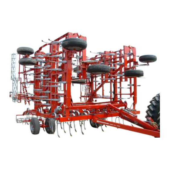
- Page 1 2800 DOUBLE FOLD FIELD CULTIVATOR *Model may not be exactly as shown. Kongskilde reserves the right to make changes to product designs and specifications without notice or obligation to rework. See your local Kongskilde representative for current product specifica- tions, instructions and options.
-
Page 2: Table Of Contents
Index Introduction & Pre-assembly Instructions: ................3 Tines: ..........................5 Mounting Wheels on the Centre Frame: ................7 Assembling the Centre Frame: ...................8 Self Levelling Linkages & Hair Pins: ................9 Hinge Assembly: ......................11 Cross Brace Installation: ....................12 Hitch Assembly: .......................13 Cylinders: .........................15 Wing Cylinder Pins:...................... -
Page 3: Introduction & Pre-Assembly Instructions
Introduction: Please take the time to carefully read all the instruction booklets provided with your new Kongskilde product. Once you are finished reading do not throw these guides out. Keep them for later review. The "Spare Parts List" is referenced to by this guide. We suggest having it on hand during the assembly process. - Page 4 Support here. Safety should be the first concern of anyone assembling a Kongskilde cultivator. Such an assembly can be a safe Supporting the frame prevents damage to project, if the assembler takes the appropriate steps, and the product.
-
Page 5: Tines
Tines: Each tines must be assembled and then attached. Assembly is straight forward simply look up the exploded view of the tine in the "Spare Parts List." This contains all the information needed to assemble the individual tines. Once the tines are assembled, they must then be attached to the toolbar. - Page 6 Assembly Information for the VFM Tine: The VTM tines are larger than most other tines. For this reason this the stem of the tine will interfer with attachment of the tine to the toolbar. Hence, the tine can not be assembled prior to being attached to the toolbar. To avoid this problem assemble the tines in the following order.
-
Page 7: Mounting Wheels On The Centre Frame
Mounting Wheels on the Centre Frame: The next step in the assembly is attaching the wheels to the centre frame. The top picture shows the wheel assembly and the lower picture shows the exploded view of the wheel assembly. 8000lbs. Centre frame Wheel assembly. -
Page 8: Assembling The Centre Frame
Assembling the Centre Frame: The diagram below shows how to assemble the centre frame. The front frame attaches to the rear frame as shown above. Use the bolts listed in the "parts book". Be sure to bolt both top and bottom holes in the front and back. Remember to tighten them well. -
Page 9: Self Levelling Linkages & Hair Pins
Self Levelling Linkage & Ring Cotter Pin: Check the assembly of the self-levelling linkages and make sure all of the clip pins are installed and locked. Unlocked Pin Locked Pin... - Page 10 Detail view of front linkages on the centre frame. "Self-levelling link" Front hitch pivot link...
-
Page 11: Hinge Assembly
Hinge Assembly: These diagrams show how to assemble wings and how to attach the hinges. Wing Installation: The picture below shows the centre frame and the two sections of one of the wings of the cultivator. The double fold cultivator, as you can see from the picture, folds its wings in two locations to enable this large cultivator to present a small aspect when transporting. -
Page 12: Cross Brace Installation
Cross Brace Installation: The cross brace is present on the inside wing section for 40' (12M), 43' (13M), 46' (14M) and 50' (15M) machines. The cross brace provides greater rigidity on larger wings. When Positioning the cross brace on the inside wing hand start the nuts on the all bolts and tighten in a even manner... -
Page 13: Hitch Assembly
Hitch Assembly: The Hitch must be installed before any hydraulics are operated. Assemble the hitch based on the pictures below, Compare these pictures to those of the hitch assembly in the "Spare Parts List" if further clarification is desired. - Page 14 Bottom Hole Recommended Examples of what the hitch attachment points should look like. The turn-buckle allows you to adjust the pitch of the cultivator. Lengthening the buckle raises the front, conversely shortening the buckle drops the front of the cultivator.
-
Page 15: Cylinders
Cylinders: Start by mount the wheel-lift cylinder in the location shown on the following page, with the pins de- scribed in the "Spare Parts List". The wing-lift cylinders should be attached as shown below. The ports on all wing cylinders should face to the outside of the machine. -
Page 16: Wing Cylinder Pins
Wing Cylinder Pins Install the wing cylinder pin such that it keeps the cylinder away from the frame as shown. Wing Cylinder Pin shown with roll pin Place wing cylinder pin in these locations Enlargement of picture to left The roll pin fits inside The clevis keeping the Clevis away from the Walking tandem arm. -
Page 17: Adjustment Point Attachment
Adjustment Point Attachment: Attach the adjustment arm as shown below. Extending the adjustment arm raises the wheels and lowers the body. For more information on adjust- ments refer to the "Owners Manual". 180 - 205mm (7 - 8 ") Set adjuster around 200mm (8") Lock pin... -
Page 18: Mechanical Adjust Wheel As Front Gauge Wheel
Mechanical Adjust Wheel as Front Gauge Wheel: A mechanical adjust wheel can attached to the wings. The part is symmetrical, and can therefore be attached to either wing. The method of attachment is shown below. Approximate setting. 50mm (2") -
Page 19: Fold Cylinders Installed
Fold Cylinders Installed: Be sure to place four (4) 1" (25 mm) wash- ers at rod end of cylinder. The inside wash- ers keep the clevis centred. Cylinders in folded position. Shown: Cylinders Latch Locks Wings in place In extended position. Notice the Difference in the Latch in Both Pictures Below Handle and Latch In Unlocked Postion Handle and Latch In Locked Postion... -
Page 20: Outside Wing Fold Cylinders Installed
Outside Wing Fold Cylinders Installed Cylinder in extended position When installing the outside fold cylinder pin, remember to attach the clip pin. Bolt the hinge plate to the frame. Cylinder in folded position As with the inside cylinders, be sure to place four (4) 1"... -
Page 21: Single Point Assembly
Single Point Hydraulics Instructions on 2800 Series Cultivators 1 - Be sure machine is lowered to the ground or jacked such that little or no pressure is on the lifting hy- draulic cylinders. 2 - Assemble and install single point hardware as shown on drawings below. Note that item#1 is fastened using the 1”... -
Page 22: Hydraulic Assembly Information
Hydraulic Assembly Information: For proper installation of the hose lines and fittings refer to the hose layout diagram provided later in the booklet. The hydraulic hose lines and fittings are provided in the hose kit. Secure the hoses to the frames with the hose clamps, carriage bolts and lock-nuts provided. - Page 23 NOTE: Route the fold hoses under top frame leg. To avoid any kinks or pinches on the hoses. Charge the wheel lift hydraulics by fully extending and retracting the wheel lift hy- draulic cylinders several times. Hold the hydraulic lever open at the end of the stroke to purge the air from the system.
- Page 24 The wing fold cylinders must be charged with oil before attempting to fold the cultivator. Disconnect the cylinder rod clevis from the fold bracket and place a block under the cylinders as shown. Connect the hoses to the tractor or portable hy- draulic unit and stroke the wing fold cylinders in and out several times holding the lever at the end of the stroke to remove the air from the system...
-
Page 25: Installing The Product Identification And Safety Decals
Installing the Product Identification and Safety Decals: 1) Install the Kongskilde Logo decals #600475113 and Vibro-Till 2800 decals #600475168 on both sides of the draw tongue and wing frames as shown. KONGSKILDE & 2800 Double Fold on both sides of hitch KONGSKILDE &... - Page 26 4) Install Red Safety Reflectors #600475132 on both rear fold brackets and sides of the 2800 centre section. RED REFLECTORS on Rear Hinges and side bar TOWING SAFETY TIPPING HAZARD 5) The 3 safety decals #600475170, 600475169 & 600475160 are located on the front frame between the three point hitch connection.
- Page 27 7) Install the WING FOLD SAFETY DE- CALS #600475039 on the front and rear main frame tubes on the 2800 wing frames. The decals should be centred on the tube at about eye and tractor level so they can be read clearly when the wings are folded as shown.
-
Page 28: On Completing The Assembly
On Completing the Assembly: When the cultivator frame is fully assembled check all that nuts and bolts are secure. Check the hose layout and hydraulic connections according to the hydraulic diagram. Be sure to read the Owners Manual before attempting to fold or operate the cultivator. The Owners Manual provides important instructions and safety precautions that must be followed before attempting to hook up and move the cultivator after assembly. -
Page 29: Notes
Notes: _________________________________________________________________________ _________________________________________________________________________ _________________________________________________________________________ _________________________________________________________________________ _________________________________________________________________________ _________________________________________________________________________ _________________________________________________________________________ _________________________________________________________________________ _________________________________________________________________________ _________________________________________________________________________ _________________________________________________________________________ _________________________________________________________________________ _________________________________________________________________________ _________________________________________________________________________ _________________________________________________________________________ _________________________________________________________________________ _________________________________________________________________________ _________________________________________________________________________ _________________________________________________________________________ _________________________________________________________________________ _________________________________________________________________________ _________________________________________________________________________ _________________________________________________________________________ _________________________________________________________________________ _________________________________________________________________________ _________________________________________________________________________ _________________________________________________________________________ _________________________________________________________________________ _________________________________________________________________________ _________________________________________________________________________ _________________________________________________________________________ ________________________________________________________________________ ________________________________________________________________________ ________________________________________________________________________ ________________________________________________________________________ ________________________________________________________________________ ________________________________________________________________________ 660 005 029 2007...
Need help?
Do you have a question about the 2800 series and is the answer not in the manual?
Questions and answers