
Subscribe to Our Youtube Channel
Related Manuals for JDS Uniphase HP3-60-P4

Summary of Contents for JDS Uniphase HP3-60-P4
- Page 1 A Quick Start Guide to Fiber Inspection, Cleaning, and Test INSPECT BEFORE YOU CONNECT...
- Page 2 Notice Every effort was made to ensure that the information in this document was accurate at the time of printing. However, information is subject to change without notice, and JDSU reserves the right to provide an addendum to this document with information not available at the time that this document was created.
-
Page 3: Table Of Contents
CONNECT Connect Good Fiber Connection ..............10 Fiber Connections ................10 TEST Test HP3-60-P4 Fiber Inspect + Test System .......11 Absolute Power (System Power Measurement) ....12 Relative Power (Attenuation Measurement) ......13 1. Reference Measurement..........13 2. Attenuation Measurement........14 Appendix: JDSU Video Probe Microscopes Digital Video Probe ................15... -
Page 4: Introduction To Fiber Inspection
Visual inspection is the only way to determine if fiber connectors are truly clean before mating them. HP3-60-P4 System with Integrated Power Meter The JDSU video fiber inspection probe and handheld and Patch Cord... -
Page 5: Inspect
InspeCt INSPECT buLkhEAD Select the appropriate bulkhead inspection tip that corresponds to the connector type and install onto probe. Insert the scope into the bulkhead to inspect. Determine whether clean or dirty. If clean, do not touch it and CONNECT. If dirty, and cleaning is required, CLEAN. -
Page 6: Is It Clean
Is It Clean? IS IT CLEAN Dirt is everywhere, and a typical dust particle (2–15 μm in diameter) can significantly affect signal performance and cause permanent damage to the fiber end face. Most field test failures can be attributed to dirty connectors, and most connectors are not inspected until the problem is detected, after permanent damage has already occurred. -
Page 7: Acceptance Criteria
aCCeptanCe CrIterIa IS IT CLEAN The tables below list the acceptance criteria standardized by the International Electrotechnical Commission (IEC) for single-mode and multimode connectors as documented in IEC 61300-3-35 Ed. 1.0. SINGLE-mODE CONNECTORS Zone Name Diameter Defects Scratches A. CORE Zone 0 –... -
Page 8: Clean
Clean: bulkhead CLEAN IbC™ Cleaner Guide Cap Cover Guide Cap Nozzle Nozzle Extender Lock Select the appropriate cleaning tool for Guide Cap the connector type. Pull off the guide cap. DRY CLEAN Insert the cleaning tool into the bulkhead adapter and push the cleaner Push into bulkhead into the bulkhead 2 times (2 clicks). -
Page 9: Patch Cord Cleaning (Ibc™ Cleaner)
Clean: patch cord CLEAN IbC™ Cleaner Guide Cap Cover Guide Cap Nozzle Nozzle Extender Lock Select the appropriate cleaning tool for Guide Cap Cover the connector type. Pull off the guide cap cover. DRY CLEAN Attach the cleaning tool to the connector and push the cleaner into the patch cord 2 times (2 clicks). -
Page 10: Connect
ConneCt CONNECT GOOD FIbER CONNECTION There are 3 basic principles that are critical to Light Transmitted achieving an efficient fiber optic connection: Perfect Core Alignment Physical Contact Pristine Connector Interface Clean Connection Cladding Core Today’s connector design and production techniques have eliminated most of the challenges to achieving core alignment and physical contact. -
Page 11: Test
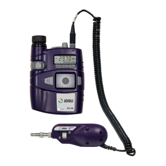
InspeCt + test system TEST hP3-60-P4 SYSTEm The HP3-60-P4 fiber inspection and test system (with integrated patch cord microscope [PCM]) combines fiber inspection and optical power measurement into a single seamless handheld device. The result is a significant increase in workflow efficiency and decrease in total inspection and test time. -
Page 12: Absolute Power (System Power Measurement)
test: power MeasureMent TEST AbSOLuTE POwER absolute power level (system power measurement) is the amount of optical power present in the system, measured in dbm. The source of this power is the transmitter or transceiver sending Patch Cord information through the system. This test determines Inspection whether the signal has enough power to operate the receiver or transceiver at the end of the link. -
Page 13: Relative Power (Attenuation Measurement)
test: reFerence MeasureMent TEST RELATIvE POwER Attenuation measurements (optical link loss) on optical components or fiber optic links (e.g., fiber connectors, cable assemblies, installed fiber optic links) are acquired by measuring the relative power level (db) at the far end of the link or device under test. -
Page 14: Attenuation Measurement
test: attenuation MeasureMent TEST ATTENuATION mEASuREmENT Network System Inspect Inspect to Probe Reference Reference Fiber 1 Fiber 2 Inspect Inspect Disconnect the power meter from reference fiber 1. Note: DO NOT disconnect reference fiber 1 from the light source (OLS). Inspect, and if necessary, clean all ends of the system port. -
Page 15: Appendix: Jdsu Video Probe Microscopes
appendIx: Jdsu Video probe Microscopes DIGITAL PRObE The westover P5000 digital probe microscope connects directly to PC/laptops via a USB 2.0 connection and operates with FiberChek2™, an advanced software that determines the acceptability of optical fiber end faces through advanced automated inspection and analysis. USB 2.0 connection to PC/laptop ANALOG PRObE The westover FbP and FbE analog probe microscopes connect directly to hD displays (HD1, HD2, HD3, or HP3-60... - Page 16 Please contact JDSU for more information. JDSU and the JDSU logo are trademarks of JDS Uniphase Corporation. Other trademarks are the property of their respective holders. © 2009 JDS Uniphase Corporation.
Need help?
Do you have a question about the HP3-60-P4 and is the answer not in the manual?
Questions and answers