Magnetrol Thermatel TA2 Installation And Operating Manual
Enhanced model.
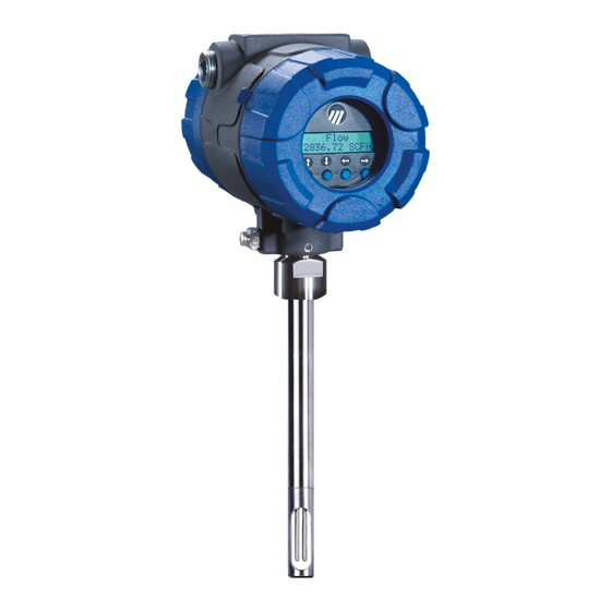
thermal dispersion mass flow transmitter.
software v2.x
Hide thumbs
Also See for Thermatel TA2:
- Installation and operating manual (84 pages) ,
- Installation and operating manual (56 pages) ,
- Installation and operating manual (36 pages)

Related Manuals for Magnetrol Thermatel TA2


Summary of Contents for Magnetrol Thermatel TA2
- Page 1 Thermatel ® Enhanced Model TA2 Software v2.x Installation and Operating Manual Thermal ispersion Mass Flow Transmitter...
-
Page 2: Thermal Dispersion Mass Flow Transmitter
They follow the procedural steps to which issue and are subject to change without notice. they refer. MAGNETROL reserves the right to make changes to the product described in this manual at any time without Cautions notice. MAGNETROL makes no warranty with respect Cautions alert the technician to special conditions that to the accuracy of the information in this manual. -
Page 3: Table Of Contents
Thermatel Enhanced Model T 2 ® Thermal Dispersion Mass Flow Transmitter Table of Contents 1.0 Quick Start Installation 2.6 Configuration Using HART .........41 ® 1.1 Probe Installation ............4 2.6.1 Connection ..........41 1.2 Wiring ..............4 2.6.2 HART Revision Table ........41 1.3 Configuration ............5 2.6.3 HART Display Menu........41 2.0 Installation 3.0 Reference Information... -
Page 4: Quick Start Installation
Quick Start Installation The TA2 is calibrated and configured with the information supplied to MAGNETROL with the order. The instrument can be installed, wired, and place directly into operation. Probe Installation Insert the probe into the pipe or duct at the appropriate location. -
Page 5: Configuration
4. Connect the 4-20 mA signal wiring to TB3. Make connec- tions to A-, A+ for an active output signal (power supplied by TA2) or P-, P+ for a passive signal using an external power supply. 5. Optional Pulse Output: connect signal wiring to TB4. Make connections to A-, A+ for an active output (power supplied by the TA2) or P-, P+ for a passive signal using an external power supply. -
Page 6: Installation
Model Number Serial Number Electrostatic Discharge (ESD) Handling Procedure MAGNETROL electronic instruments are manufactured to the highest quality standards. These instruments utilize electronic components which may be damaged by static electricity present in most work environments. The following steps are recommended to reduce the risk of component failure due to electrostatic discharge: 1. -
Page 7: Installation
Installation 2.3.1 Electronics The instrument is rated for use in Class I, Division 1 and Class I, Division 2 areas. The enclosure is also rated NEMA 4X. Remote electronics (optional) should be installed in an easy to access location within 500 feet (150 meters) of the sensor. - Page 8 For applications where it is desirable to install or remove the probe without having to shut down the process, The MAGNETROL Retractable Probe Assembly (RPA) can be utilized. See the TA2 Sales Brochure (MAGNETROL bulletin 54-140) for more information. WARNING To avoid potential damage or injury, never loosen a compression fitting while sensor is under pressure.
-
Page 9: Wiring
Wiring There are two connections in the electronics enclosure for ⁄ " NPT or M20 connections. These are generally used as one connection for input power and one for output signal. 2.4.1 Power and Signal Connection The instrument has separate wiring connections for AC (100 to 264 VAC) and DC (15 to 30 VDC). -
Page 10: Ground Connection
2.4.2 Ground Connection The instrument must be grounded in accordance with Article 250 of the National Electric Code. 2.4.3 4-20 mA Output A 4-20 mA output (Analog Output 1) of the flow rate is DC INPUT LOOP1/HART PULSE/ INPUT ALARM OUTPUT available at terminal block TB3. -
Page 11: Remote Electronics
2.4.5 Remote Electronics Power/Loop Board in If the electronics are remote from the probe, a remote Electronics Housing board with terminal blocks is provided in the housing on the probe. For cable lengths up to 150 feet, the connection between the probe and electronics should be an 8-conductor shielded cable (Belden 8104). -
Page 12: Configuring The Transmitter
Configuring the Transmitter The TA2 electronics are easy to set up and configure to the user’s specifications. When specified with the order, the configuration settings are programmed into the instrument at the factory. If not, or if the user wants to modify the configuration settings, follow these instructions for config- uring the instrument. -
Page 13: Operator Keypad
2.5.2 Operator Keypad The TA2 has a local user interface using a 2-line ¥ 16- character liquid crystal (LCD) and 4-push-button keypad. All measurement data and configuration information is shown in the LCD. The TA2 is configured via a “tree” type menu structure where it is easy to access branches of the tree to configure the various parameters. -
Page 14: Numeric Entry
2.5.2.3 Numeric Entry The Numeric Entry Mode is used to enter numeric values. This mode is accessed when the Enter Key is pressed on a menu item that requires entry of a numeric value. Data is entered at the cursor position: Push Button Keystroke Action Moves to the next digit (0,1,2,3…9). -
Page 15: Character Data Entry Mode
This mode is most commonly used when entering a new local tag line into the TA2. The local tag as shipped from the factory is “MAGNETROL TA2” and can be changed to permits the user to identify the instrument with a the actual tag line of the instrument or the service. -
Page 16: Password
2.5.3 Password A password protection system restricts access to portions of the menu which affect the unit’s operation and configura- tion. The default user password installed in the TA2 at the factory is 0 which effectively disables the user password feature. - Page 17 TA2 User Interface Menu Hierarchy Overview Home Measured Values See Page 18 Basic Config Flow rea See Page 20 I/O Config O1 Loop Config See Page 21 See Page 21 O2 Loop Config See Page 21 dvanced Config Totalizers See Page 26 See Page 23 Secondary loop, Transistor Output and HART...
-
Page 18: Run Mode
2.5.5 Run Mode The Run Mode is the normal display for the TA2. The user has the option of selecting displayed values such as Flow, Mass, Temperature, Totalized Flow, Tag Line, Custom Units, or mA output. These values will rotate at 2-second intervals on the display during operation. - Page 19 Diagnostics which have these options (Model TA2-A4XX-XXX). to select Local Tag Magnetrol TA2 Factory Config to select Custom Units nnnn units TA2 User Interface Home and Associated Menus Alarm Status nnnn units...
-
Page 20: Basic Configuration Menu
2.5.7 Basic Configuration Menu The Basic Configuration menu is used to select the display units and enter specific information for the application. Access this section by pressing Enter when Basic Config is displayed from the Main Menu. To calculate the flow or mass, it is necessary to accurately enter the inside area of the pipe or duct. If the pipe or duct is circular, simply enter the inside diameter;... -
Page 21: I/O Configuration Menu
2.5.8 I/O Configuration Menu The I/O Configuration menu is used to set up the operations of 4–20 mA output, the totalizer, and the pulse/alarm output. I/O Config A01 Loop Config Loop Control Flow to select to select [selection] Mass decimal entry LRV (4 mA) Set in selected [entered value]... -
Page 22: Totalizer
The previous page shows the I/O configuration menu for setting up the 4-20 mA loop, the Totalizers, and the Damping. The basic TA2 has a single 4-20 mA loop referred to as AO1. Optionally the TA2 can be provided with a second 4-20 mA loop referred to as AO2 and a Transistor Output that can be configured to provide either a Pulse Output or an Alarm Output (see page 10 for speci- fications). - Page 23 Totalizers Totalizer Units to select [selection] R Total Mode Disabled Enabled [selection] R Total Mult 1,000 [selection] 10,000 100,000 R Totalizer nnnnnnn units R Total Time nnnnnh nnm nns R Totalizer Are You Sure? Reset [selection] NR Total Mult 1,000 [selection] 10,000 100,000...
-
Page 24: Transistor Output
2.5.10 Transistor Output The optional transistor output can be configured to provide a pulse output proportional to the flow rate or an alarm indication where the output can serve as a low flow or a high flow alarm indication. When used as a pulse output a multiplier factor can be applied. A selection of maximum frequency ensures that the pulse output from the TA2 does not exceed the maximum allowable frequency of any external counter. -
Page 25: Pulse Rate Calculation Example
Configuration Parameter Explanation Selects the operation of the transistor output. Can be set up for Pulse Output, Output Function Alarm, or Disabled. Default is disabled. Permits selection of the units for the pulse output. Select SCF (Standard Cubic Feet), Pulse Output Units (Normal Cubic Meters), Nl (Normal Liters), lb (Pounds), or kg (Kilograms). -
Page 26: Advanced Configuration Menu
2.5.11 Advanced Configuration Menu The Advanced Configuration menu sets advanced parameters that may occasionally be required for proper operation of the TA2. Advanced Config New Password decimal entry to select [entered value] Install Factors A+Bx+Cx^2, A= decimal entry to select [entered value] A+Bx+Cx^2, B= decimal entry... - Page 27 alphanumeric Custom Unit Custom Unit Text entry to select [entered value] (6 characters) Custom Unit Mult decimal entry [entered value] Previous Menu to select D/A Trim A01 D/A Trim 4 mA [inc/dec] to select [value] D/A Trim 20 mA [inc/dec] [value] Previous Menu to select...
-
Page 28: Custom Unit Multiplier Example
0, then the new password will be required whenever any configuration values are changed. If the user changes the password, the display will show an encrypted value. Contact MAGNETROL Technical Support with this value to determine the actual password which was last entered. -
Page 29: Device Information
Configuration Parameter Explanation From the factory this tag is shown as “MAGNETROL TA2” but this can be changed to describe the application or the flow transmitter number. The tag can contain a maxi- Input Local Tag mum of 16 characters. All upper and lower case letters, numbers and other charac- ters are provided for the tag. -
Page 30: Diagnostics Menu
2.5.13 Diagnostics Menu The Diagnostics Menu contains both informational items and diagnostic screens that can assist in obtaining information on the operation of the unit and troubleshooting if faults or warnings occur. Previous Menu to select Diagnostics History Event nn Eventnn Occurred nnnnnh nnm nnsec to select... - Page 31 Configuration Parameter Explanation Displays the present status and the sequence in which any diagnostic events may have occurred. The second line of the menu shows the present status. If there are no present diagnostic events, this screen will have History on the top line and OK on the bottom line.
- Page 32 2.5.13 Diagnostics Menu (cont.) Min Elec Temp Reset? [min value] [selection] Probe Status Temp Sensor TA2 User Interface to select OK/Shorted/Open Diagnostics Menu Flow Sensor OK/Shorted/Open Probe Heater OK/Shorted/Open Previous Menu to select Zero Power Test Delta T Unstable Delta T Stable to test [temperature] [temperature]...
- Page 33 Configuration Parameter Explanation Min Elect Temp Displays the minimum temperature which the electronics have recorded. Press to select and then the arrows to scroll between the Temp Sensor, Flow Sensor, and Probe Heater. If the probe is operational, the display Probe Status will show “OK”.
- Page 34 2.5.13 Diagnostics Menu (cont.) Hi Cal Validate Delta T Unstable Saved Test DeIT Save Temp? to test [temperature] [temp] [temp] [selection] Amb T Unstable [temperature] A01 Loop Test [inc/dec] [current value] Secondary loop configuration is A02 Loop Test only available [inc/dec] on units which [current value]...
- Page 35 Configuration Parameter Explanation Shows the current mA value output on the 4–20 mA output signal for the first (AO1) AO1 Loop Test loop. This value can be increased or decreased by pushing the arrows. Pressing returns the mA signal to normal operation. Shows the current mA value output on the 4–20 mA output signal for the second (AO2) loop.
-
Page 36: Factory Configuration
Provides the calibration parameters for Gas B (if specified) — Cal Parameters B see separate section 2.5.17. Control Parameters Factory set parameters which should only be changed under direction of MAGNETROL Module Params Module Parameters—Factory set parameters 54-631 THERMATEL Model TA2 Transmitter... -
Page 37: Probe Parameters
2.5.15 Probe Parameters These parameters are specific characteristics defining the operation of the probe. Probe Params Sensor Type to select [selection] Spare 1 Spare 2 Spare 3 decimal entry [entered value] decimal entry [entered value] Probe Temp Calib Temp Stabilizing Enter Probe Temp [OK/Bad/Calib [lo temp ADC cnt] Temp... -
Page 38: Calibration Parameters
Indicates the temperature difference which the TA2 is attempting to maintain. Set Point This parameter should only be changed under direction of MAGNETROL. Used to adjust the zero flow data point, if necessary, for application-specific related issues. Zero Flow Signal See Troubleshooting Section 3.4. -
Page 39: Gas Parameters
Provides the density of the gas at the specified STP (Standard Temperature Gas Density and Pressure) conditions. Contains factors which relate the relationship of the gas flow to the flow of air. Air Equivalency Contact MAGNETROL for factors specific to different gases. 54-631 THERMATEL Model TA2 Transmitter... -
Page 40: Air Equivalency Calibration
2.5.18 Air Equivalency Calibration The Air Equivalency calibrations permits the use of an air calibration and then, using the MAGNETROL historic data base, relate the flow of air to the flow of gas. The equations use a polynomial curve fit. -
Page 41: Configuration Using Hart
Configuration Using HART ® A HART ® (Highway Addressable Remote Transducer) Analog Output 1 remote unit, such as a HART communicator, can be used DC Power input Output (15 – 30 VDC) Active or Passive to provide a communication link to the TA2. AC Power input connections (100 –... - Page 42 2.6.3 HART Menu 1 Flow Units 2 Mass Units 1 Device Setup 1 Basic 1 System Units 2 Diagnostics ¿ Configuration 2 Flow Area 3 Temperature Units 3 PV 4 Density Units 5 Totalizer Units 4 PV Loop 6 Diameter Units 5 PV % Range 7 Area Units 6 SV...
- Page 43 8 Manufacturer 9 Model Number 10 Specific Model 1 Coeff Ratio 11 Firmware Version 2 Slope 12 MAGNETROL S/N 3 Power Predictor 13 Device ID 4 Factory Parameter 1 14 Final asmbly num 5 Factory Parameter 2 6 Factory Parameter 3...
- Page 44 4 Device Information 5 Factory Configuration 6 Review 1 Model 26 Damping 2 Manufacturer 27 AO2 Lwr Range 3 MAGNETROL S/N Value 4 HART Tag 28 AO2 Upr Range 5 Descriptor Value 6 Firmware Version 29 R Totalizer Mode 7 Date...
- Page 45 2.6.3 Diagnostics Menu 1 Device Setup PV Out of limits 2 Diagnostics Non-PV Out of limits 3 AO1 Loop Current Saturated 4 AO1 Loop Loop Current Fixed 5 AO1 % Range More status available 6 AO2 Cold start 7 AO2 Loop Configuration changed 8 AO2 % Range Device malfunction...
-
Page 46: Reference Information
Each instrument is calibrated and configured by MAGNETROL for the type of gas, pipe size, flow area and flow rate. Calibration is performed in a NIST trace- able flow bench. The TA2 provides real-time temperature compensation which adjusts the flow measurement due to changing gas properties caused by process temperature changes. -
Page 47: Display Module
Use of the PACTware ™ PC program is highly recommended and invaluable for troubleshooting and advanced configuration. A HART RS232 or USB model (purchased separately) is required. See MAGNETROL PACTware ™ bulletin 59-101. 54-631 THERMATEL Model TA2 Transmitter... - Page 48 Troubleshooting Symptom Problem Solution No Output signal No input power Verify that LED D6 on the input wiring board is on. If not, check wiring connections. No Display Check F1 test and F2 test to check fuses protecting input wiring. See Figure 8. No Output signal 4–20 mA output Verify that 4–20 mA connections are...
-
Page 49: Error Messages
3.4.1 Error Messages The TA2 Mass Flow Meter utilizes a 3-level hierarchy for reporting diagnostics information: FAULTS, WARNINGS, and INFORMATION. Faults and Warnings can be reviewed on the rotating screen in the Home menu. These screens capture only current conditions. Historic diagnostic infor- mation can be viewed in the HISTORY screen of the Diagnostics Menu. -
Page 50: Fault Messages
Module Failure Module Failure Requires replacement of processor board or return of unit to factory. Velocity is greater than The velocity is greater than established values. Vel > UprSnsrLmt the Upper Sensor Limit Contact MAGNETROL. 54-631 THERMATEL Model TA2 Transmitter... -
Page 51: Warning Messages
Calibration Point. The URV (Upper Range Value) is too close to the LRV Insufficient Span SetPts Too Close (Lower Range Value). Increase separation. Non-fatal firmware exception. Advise MAGNETROL with system System Warning System Code code number. 54-631 THERMATEL Model TA2 Transmitter... -
Page 52: Diagnostics Test
Watch the video for this procedure at www.magnetrol.com/thermalmassflow. 54-631 Thermatel ® Model TA2 Transmitter... - Page 53 If the temperature difference measured during the test is greater than the recommended temperature difference indicated above in item “iii”, then the overall accuracy of the TA2 may be affected. Contact MAGNETROL Technical support. 54-631 THERMATEL Model TA2 Transmitter...
-
Page 54: Maintenance
This infor- mation is contained on the calibration certificate which can be supplied by MAGNETROL. Use of PACTware ™ is recommended for re-entry of this data. -
Page 55: Probe Replacement
The probe and processor board are calibrated together to form a matched set. If a probe needs to be replaced, MAGNETROL will provide a new calibration certificate. The user will be required to re-enter the data from this cer- tificate into the instrument. Use of PACTware ™... -
Page 56: Rtd Calibration
If replacing the processor board, use the set point and ZFS on the original calibration certificate. If the original cali- bration certificate is not available, contact MAGNETROL with the serial number of the unit found on the name- plate. -
Page 57: Flow Recalibration
NOTE: If the TA2 is calibrated for a gas other than air, there are two ZFS values on the certificate. One is for air and the other is for the particular gas. Use the ZFS for air when making the adjustment in air. - Page 58 HART. These values should be entered in increasing order to ensure a monotonically increasing curve. Note password of 126 is required for entry of calibra- tion data. (Contact MAGNETROL if issues using this password.) d. After completion of entry of the calibration data, check the display/HART/PACTware ™...
-
Page 59: Agency Approvals
IEC 60079-1: 2007-04 T medium= -40° C to +55° C TXR-XXXX-XXX (probe) TFT-XXXX-000 (flow body) TA2-AXXX-X3X Russian Authorization Standards - TA2-AXXX-X4X Consult MAGNETROL for Details BRAZIL Ex d IIc T6 Gb TA2-AXXX-X3X Explosion proof TA2-AXXX-X4X ABNT NBR IEC 60079-0:2008 IP66W ABNT NBR IEC 60079-1:2009 -40°... - Page 60 54-631 THERMATEL Model TA2 Transmitter...
-
Page 61: Replacement Parts
Replacement Parts NOTE: Replacement of the processor circuit board or the probe requires entry of calibration and configuration data from the Calibration Certificate. WARNING: EXPLOSION HAZARD Substitution of components may impair suitability for Class I, Division 2 EXPLOSION HAZARD Do not disconnect equipment unless power has been switched off, or the area is known to be non-hazardous Item Description... -
Page 62: Specifications
Specifications 4.7.1 Performance Flow range maximum 10–54,000 SFPM (0.05–275 Nm/s) air reference to standard conditions Contact MAGNETROL for other gases Accuracy flow ±1% of reading +0.5% of calibrated full scale Accuracy temperature ±2° F (1° C) Repeatability ±0.5% of reading... -
Page 63: Physical
4.7.5 Physical – inches (mm) 4.49 (114) " NPT or M20 connection 5.18 6.49 (132) (165) Optional compression Dimension A: fitting 3.33 (85) without display 3.88 (99) with display " or 1" NPT recommended Dimension B: Insertion Length 3.88 (99) Pipe centerline 1"... - Page 64 4.7.5 Physical – inches (mm) Length (L) Overall Height (B) Height to Code Size Centerline With Flow Without Flow With Flow Without Flow Flange Conditioning Conditioning Conditioning Conditioning ⁄ " 8 (203) — 5 (127) — 8.0 (203) 8.4 (213) 9.7 (246) ⁄...
-
Page 65: Model Numbers
Model Numbers 4.8.1 Transmitter SIGNAL OUTPUT 4-20 mA 4-20 mA with HART fieldbus OUNDATION 4-20 mA with HART, Pulse/Alarm, second mA Output DISPLAY None Plug-in display with keypad (with window) CALIBRATION–INSERTION PROBE CALIBRATION–FLOW BODY Actual Gas Calibration Actual Gas Calibration ¿... -
Page 66: Insertion Probe
4.8.2 Insertion Probe THERMATEL PROBE Probe length in inches Probe length in centimeters PROBE TYPE ⁄ " diameter probe MATERIALS OF CONSTRUCTION 316/316L Stainless Steel Hastelloy C PROCESS CONNECTION SIZE Compression Fitting Utilized (customer supplied) ⁄ " NPT SS compression fitting with Teflon Ferrules ⁄... -
Page 67: Flow Body
4.8.3 Flow Body MATERIALS OF CONSTRUCTION All stainless steel Carbon steel body with stainless steel sensor SIZE ⁄ inch ⁄ inch 1 inch ⁄ inch 2 inch 3 inch 4 inch PROCESS CONNECTION TYPE NPT Threads ¿ 150# Flange Only when digit 5 = 0, 1, 2, 3, or 4 ¿... -
Page 68: Connecting Cable
4.8.4 Connecting Cable FOR CABLE LENGTHS UP TO 150 FEET 037-3313-XXX (Cable length in feet)—10 feet minimum, 150 feet maximum length Example: 50 feet = 050 FOR CABLE LENGTHS UP TO 45 METERS 037-3314-XXX (Cable length in meters)—3 meters minimum, 45 meters maximum length Example: 8 meters = 008 FOR CABLE LENGTHS BETWEEN 150 AND 500 FEET... -
Page 69: Glossary
Standard Temperature and Pressure (STP) PSI : Absolute pressure in pounds per square inch. conditions. MAGNETROL uses default of +70° F and Zero psia is an absolute vacuum. one (1) atmosphere for STP conditions. The STP con- ditions may be modified to match the user’s standards. -
Page 70: Ppendix
Appendix A The flow measurement of the TA2 assumes that the end of the probe is one inch past the centerline and the presence of a fully developed flow profile. See Figure A. = 3,000,000 = 4,000 Figure B Flow Profile Following Single Elbow Figure C, below, indicates the minimum recommended straight- run distances required to obtain the desired fully developed flow... - Page 71 Appendix A (continued) Conditioning Plates Flow conditioning plates may be provided in applications where installed 8 pipe diameters downstream of the plate with 5 diame- limited straight run is available. Plates are available in flow body ters required downstream of the TXR. For TFT designs with the type sensor designs (TFT) from 1.5”...
- Page 72 Appendix A (continued) 1000 1.5" 2" 3" 4" 5" 6" 8" 10" 0.01 0.001 0.0001 1000 10000 Flow Rate (SCFM) 1000 1.5" 2" 3" 4" 5" 6" 8" 10" 0.01 0.001 0.0001 10000 1000 Flow Rate (Nm3/h) 54-631 THERMATEL Model TA2 Transmitter...
-
Page 73: Ppendix B
MAGNETROL refers to the use of a separate power supply as a between the flow computer and the active TA2 pulse output. -
Page 74: Ppendix C
Appendix C Enhanced TA2 Pulse Output The Enhanced TA2 has an option for providing a pulse output. Frequency: Represents the maximum frequency of the pulses. The Pulse is an open collector output; the output can be either a This is selectable from 10 to 10,000 Hz. This value should not powered (active) connection or a passive connection using an exceed the maximum input rate of the device receiving the pulses. -
Page 75: Flow Pplication Questionnaire
Maximum Normal Minimum Units Flow Rate Temperature Pressure STP Conditions Specify Standard Temperature and Pressure conditions (If not specified Magnetrol uses 70° F and 1 Atmosphere) Temperature: Pressure: 1 Atmosphere 1 Bar PIPE DIMENSIONS DUCT INTERNAL DIMENSIONS Pipe Diameter: inch Schedule... - Page 76 705 Enterprise Street • Aurora, Illinois 60504-8149 • 630-969-4000 • Fax 630-969-9489 info@magnetrol.com • www.magnetrol.com Copyright © 2015 Magnetrol International, Incorporated. All rights reserved. Printed in the USA. MAGNETROL & MAGNETROL logotype and THERMATEL are registered trademarks of MAGNETROL International, Incorporated...
Need help?
Do you have a question about the Thermatel TA2 and is the answer not in the manual?
Questions and answers