Table of Contents
Advertisement
Quick Links
SIL Certified Safety Manual
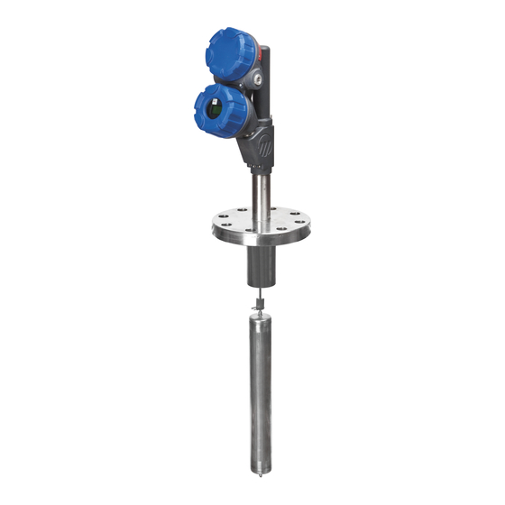
for E3 Modulevel
Model E3X-XXXX-SXX
Liquid Level
Displacer Transmitter
This manual complements and is intended to be used with the
Magnetrol
E3 Mod ulevel
®
®
Installation and Operating manual ( ulletin 48-635).
Safety Function
The HART
version of the E3 Modulevel
®
measure level and transmit a signal proportional to that level
within the stated safety accuracy of ±2% of span (or the
measured error published in I/O Manual 48-635, whichever
is greater). In addition, when continuous, automatic diagnos-
tics detect that the transmitter cannot perform this function,
the output will be driven to the customer-specified out-of-
range signal (i.e., 3.6 mA or 21 mA).
The E3 MODULEVEL is certified for use in low demand
level measurement applications.
Application
The HART
version of the E3 MODULEVEL level trans-
®
mitter can be applied in most process or storage vessels, bri-
dles, and bypass chambers up to the transmitter's rated tem-
perature and pressure. The E3 MODULEVEL can be used
in liquids, clean or dirty, light hydrocarbons to heavy acids
(SG=0.23 to 2.20) to meet the safety system requirements of
IEC 61508 (Edition 2.0, 2010).
Benefits
• Level protection to SIL 3 as certified by exida Certification
per IEC 61508.
• Level ranges from 14 to 120+ inches
(356 to 3048+ mm).
• Process temperatures to +850 °F (+454 °C) for non-steam
applications, +800 °F (+427 °C) for steam applications
• Process pressures to 5150 psi (355 bar).
• Continuous self-test with 22 mA or 3.6 mA fault indica-
tion fully compliant with NAMUR NE 43.
• IS, XP, and Non-Incendive approvals.
• Emission and immunity compliance to EN 61326.
• Two-wire, loop-powered transmitter for level,
interface, or density measurement.
®
Liquid Level Displacer Transmitter
transmitter will
®
Advertisement
Table of Contents

Related Manuals for Magnetrol E3 Modulevel series


Summary of Contents for Magnetrol E3 Modulevel series
- Page 1 E3 Modulevel ® Model E3X-XXXX-SXX Liquid Level Displacer Transmitter This manual complements and is intended to be used with the Magnetrol E3 Mod ulevel Liquid Level Displacer Transmitter ® ® Installation and Operating manual ( ulletin 48-635). Safety Function...
-
Page 2: Table Of Contents
E3 Modulevel Displacer Level Transmitter ® SIL Manual for E3 Modulevel ® E3X-XXXX-SXX Table of Contents 1.0 Introduction ..............3 6.6 Site Acceptance Testing ..........8 1.1 Product Description ..........3 6.7 Recording Results............8 1.2 Theory of Operation..........3 6.8 Maintenance .............8 1.3 Determining Safety Integrity Level (SIL) ....4 6.8.1 Diagnostics and Response Times ....8 2.0 Applicable Models ............4 6.8.2 Troubleshooting ..........9... -
Page 3: Introduction
Introduction Product Description The E3 MODULEVEL is a loop-powered, two-wire, Table 1 24 VDC level transmitter that uses simple buoyancy princi- Enhanced E3 MODULEVEL ples in combination with a precision range spring and a Model Numbers highly accurate LVDT (linear variable differential trans- Transmitters: former) to detect and convert liquid level changes into a Model E3 MODULEVEL,... -
Page 4: Determining Safety Integrity Level (Sil)
Table 2 Determining Safety Integrity Level (SIL) SIL vs. PFDavg Safety Target Average Safety Instrumented System designers using the Integrity Level probability of failure E3 MODULEVEL must verify their design per applicable (SIL) on demand (PFDavg) ≥10 standards. to <10 ≥10 to <10 Three limits must be met to achieve a given SIL level:... -
Page 5: Miscellaneous Electrical Considerations
.• The only unsafe mode is when the unit is reading an incorrect level within the 4–20 mA range (> ±2% deviation). • MAGNETROL defines the faulted mode as one in which the 4–20 mA current is driven out of range (i.e., less than 3.8 mA or greater than 21.5 mA). -
Page 6: Supplementary Documentation
Supplementary Documentation The E3 MODULEVEL Installation and Operating Manual (Bulletin 48-635) must be available for installation of the measuring system. The following Electronic Device Description File is required if HART is used: Manufacturer Code 0x56 Model E3 MODULEVEL Device ID OxE3, device revision 2 DD revision 1 For device installations in a classified area, the relevant safety instructions and electrical codes must be followed. -
Page 7: Installation
Installation Refer to the E3 MODULEVEL Installation and Operating Manual 48-635 manual for complete installation instruc- tions. • Contains information on the use, changing and resetting of the password-protection function. • Provides menu selection items for configuration of the transmitter as a level sensing device. •... -
Page 8: Write Protecting /Locking
Results of Site Acceptance Testing must be recorded for future reference. Maintenance The only maintenance required is the proof test. • Report all failures to Magnetrol ® • Firmware can be upgraded only by factory personnel. 6.8.1 Diagnostics and Response Times Continuous internal diagnostics are present within the E3 MODULEVEL transmitter. -
Page 9: Troubleshooting
C) Safety Function Response Time: 3 seconds (with Damping=0) 6.8.2 Troubleshooting Report all failures to the MAGNETROL Technical Support Department. Refer to the E3 MODULEVEL Installation and Operating Manual Bulletin 48-635 for troubleshooting device errors. To assist in finding errors should they occur, at start-up... -
Page 10: Suggested Proof Test
7.1.4 Suggested Proof Test The suggested proof test for the E3 is described in the fol- lowing table. The end user must use calibrated equipment to measure the output in steps 3, 4, and 6. Step Action Bypass the safety function and take appropriate action to avoid a false trip. Use HART communications to retrieve any diagnostics and take appropriate action. -
Page 11: Safety Requirements
Safety Integrity Function, SIF. Magnetrol cannot directly control the user life cycle of a SIF using this product but needs to have assumptions on how the product will be used. -
Page 12: Safety Function Requirements
Safety Function Requirements This section lists the Safety Function Requirements that specify what safety relevant functionality is to be performed for implementation of the safety integrity function and also to maintain the desired level of safety integrity. These requirements may also rule out particular functionality for SIF usage that could lead to designs that are difficult to vali- date for deterministic performance or safety integrity. -
Page 13: Appendices
Appendices SIL Certificate 48-651 SIL Certified Safety Manual for E3 Modulevel ®... -
Page 14: Fmeda Report: Exida Management Summary
FMEDA Report: exida Management Summary ® 48-651 SIL Certified Safety Manual for E3 Modulevel... -
Page 15: Specific E3 Modulevel Values
Specific E3 MODULEVEL Values E3 MODULEVEL Product Model E3X-XXXX-SXX SIL 2 90.6% PFD avg Refer to FMEDA report Report: Lifetime of Critical Components According to section 7.4.9.5 of IEC 61508-2, a useful life- time, based on experience, should be assumed. Although a constant failure rate is assumed by probabilistic estimation method, this only applies provided that the useful lifetime of components is not exceeded. - Page 16 84.00.01-2004” Disclaimer The SIL values in this document are based on an FMEDA analysis using exida’s SILVER Tool. MAGNETROL accepts no liability whatsoever for the use of these numbers or for the correctness of the standards on which the general calculation methods are based.
Need help?
Do you have a question about the E3 Modulevel series and is the answer not in the manual?
Questions and answers