Table of Contents
Advertisement
Quick Links
Advertisement
Table of Contents

Subscribe to Our Youtube Channel
Related Manuals for Magnetrol Thermatel series


Summary of Contents for Magnetrol Thermatel series
- Page 1 Thermatel ® Thermal Dispersion Mass Flow Measurement Handbook...
-
Page 2: Table Of Contents
Table of Contents Introduction ....................1 What is Mass Flow Measurement?..............1 Types of Flow Transmitters ................4 Differential Pressure..................4 Orifice ......................4 Venturi ......................6 Averaging Pitot Tube ..................7 Vortex Shedding ....................7 Turbine Flow Meters ..................8 Ultrasonic Flow ....................9 Coriolis......................9 Pressure/Temperature Correction..............10 Multi-Variable Transmitters ................10 Thermal Mass Flow ..................11 Different Types of Thermal Mass Flow Meters ..........13 Response Time ....................14... -
Page 3: Introduction
Introduction Accurate mass flow measurement of gas is difficult to obtain. The main reason is that gas is a compressible fluid. This means that the volume of a fixed mass of gas depends upon the pressure and temperature it is subject to. Consider a balloon containing one actual cubic foot of gas at room tempera- ture (70°... - Page 4 The simplest way of measuring mass flow of gas is in units of cubic feet per minute or cubic meters per hour, corrected to STP conditions. This is referred to as SCFM (standard cubic feet per minute) or the metric equivalent of /h (normal cubic meters per hour).
- Page 5 Once we establish a set of conditions as a standard temperature and pressure (STP conditions), we can convert between the flow rate at actual conditions and the flow rate at standard conditions. ( )( ) SCFM = ACFM The subscript (a) refers to actual conditions; the subscript (s) refers to stan- dard conditions.
-
Page 6: Types Of Flow Transmitters
Types of Flow Transmitters There are many types of flow transmitters — some are used for both liquid and gas flow measurement, while others are specifically used for one fluid. The following table identifies many of the different types of flow transmitters and their use in liquid, steam, or gas service, and if they measure actual flow or mass flow. - Page 7 This method of flow measurement utilizes a proven technical concept called “Bernoulli’s Equation.” This relation states that the pressure drop across a flow restriction is based upon the square of the flow: ∆P ⁄ Flow = constant × The flow rate is based upon flow at actual operating conditions. The pressure drop across the flow element is proportional to the square of the flow.
-
Page 8: Venturi
3. Creates pressure drop. Because the flow measurement is based upon measuring a differential pressure, the flow measurement requires that additional pressure drop be added to the process, which increases operating cost. The pressure drop created by the primary element is frequently overlooked when considering operating cost. -
Page 9: Averaging Pitot Tube
Averaging Pitot Tube The averaging pitot tube can be an effective differential pressure flow measure- ment device. It is an insertion device that measures the average velocity across the pipe as shown in the illustration below. While this type of instrument is effective for liquid and steam flow, it has limitations with gas flow measurement, particularly low flow sensitivity and turndown. -
Page 10: Turbine Flow Meters
There are limitations when using this technology for measurement of gas flow rates: 1. Vortex flow meters measure the actual flow rate moving past the flow element. To convert to mass flow, it is necessary to measure pressure, temperature, and use a flow computer to calculate mass flow. 2. -
Page 11: Ultrasonic Flow
Ultrasonic Flow Ultrasonic technology is used to measure the velocity of the fluid in a closed pipe. The sensors can be either insertion type or a non-invasive type, which clamp onto the side of the pipe. When there is flow, the time for a pulse to go between the downstream and upstream transducer will be longer than the time from the upstream to the downstream transducer. -
Page 12: Pressure/Temperature Correction
Pressure/Temperature Correction As previously discussed, many flow meters measure the actual flow rate at operating conditions rather than the mass flow rate. In order to obtain a mass flow measurement, it is necessary to correct for the actual pressure and tem- perature. -
Page 13: Thermal Mass Flow
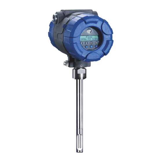
6. Factory Calibrated. Each instrument is calibrated by MAGNETROL for the application specific requirements and configured to the user’s specifications. The instrument can be installed and placed directly into service without any need for field set up, calibration, or adjustment. - Page 14 MAGNETROL offers the TA2 thermal mass flow meter to meet a broad range of user’s application requirements: Model TA2 with Model TA2 Insertion Probe with Flow Body The sensor used with the MAGNETROL Thermal Mass Flow meter is illustrated in Figure 9.
-
Page 15: Different Types Of Thermal Mass Flow Meters
There are two different technologies utilized for thermal mass flow measurement. Both methods obtain the same results, and the user should not be concerned which method is used. MAGNETROL has experience with both technologies. Constant Temperature Difference This technology maintains a constant temperature difference between the heated sensor and the reference sensor. -
Page 16: Response Time
The temperature difference decreases as the flow rate increases. This was the method utilized in the TA1, the first generation thermal mass flow meter of MAGNETROL. At low flow rates the temperature difference between the sensors is greatest. -
Page 17: Temperature Compensation
These properties include thermal conductivity, gas viscosity, density and specific heat. MAGNETROL has done extensive testing and analysis on the effect of changes in flow at different temperatures and has developed a proprietary method of providing temperature compensation over the entire operating range of the instrument. - Page 18 What these manufacturers overlook is that the gas properties that affect convective heat transfer are temperature dependent. Thus changing temperature changes heat transfer. MAGNETROL provides real time temper- ature compensation that measures the temperature of the gas and automatically corrects the mass flow measurement based on temperature variations.
-
Page 19: Pressure Effects
Pressure Effects Heat transfer is affected by changing temperature. This is based upon both theory and the experience of MAGNETROL. However, heat transfer is not affected by changing pressures. The chart below demonstrates that pressure does not affect thermal mass flow measurement. -
Page 20: Calibration
Direct calibration on the actual gas is commonly performed and will provide best results. There are occasions where the user is looking for close and repeat- able flow measurements. In these cases MAGNETROL can provide an Air Equivalency calibration. Every time we perform a direct calibration on a gas, we also calibrate on air. - Page 21 This can also occur for safety reasons where some gases cannot be handled in a flow bench. When either of these two situations occur, MAGNETROL can perform a gas correlation. For these calibrations we calibrate on two different gases with known thermal properties. This defines the heat transfer characteristics of the sensor.
-
Page 22: Calibration Vs. Configuration
± 1% of reading plus 0.5% of full scale. In reality the accuracy will be better than this. MAGNETROL uses a spline curve where the calibration curve goes directly through the data points. The following curve shows actual calibration data points, allowable error with other data points taken in between the calibration data points. -
Page 23: Flow Profile
This also shows that the greater the number of data points the better the over- all accuracy. MAGNETROL uses a minimum of 10 data points and sometimes up to 30 data points depending upon the calibration range. Other manufac- turers may only use a zero flow point and 4 calibration data points yet claim the same accuracy. - Page 24 Flow Laminar Flow Figure 18 With turbulent flow, the flow path consists of eddies and swirls within the fluid; there is intermixing as the fluid flows. Typical turbulent flow is shown in Figure 19. Flow Turbulent Flow Figure 19 Turbulent flow and laminar flow have very specific definitions based upon the Reynolds number.
- Page 25 Laminar Flow Profile Figure 20 A fully developed turbulent flow profile is shown in Figure 21. Virtually all gas flow applications will be in the turbulent flow area. Turbulent Flow Figure 21 Theoretically the velocity at the pipe wall is zero and the velocity at the centerline is approximately 20% higher than the average velocity.
- Page 26 In turbulent flow, the location of the average velocity will range between 0.07 D ( ⁄ the diameter) to 0.13 D ( ⁄ the diameter), depending upon the Reynolds number. At this location, changes in velocity (Reynolds number) will change the flow profile. The center line velocity in turbulent flow is approximately 20% greater than the average velocity.
-
Page 27: Installation Options
5 diameters downstream was considered as adequate straight run. Recent testing by NIST has demonstrated that these dimensions may not be sufficient, especially if there are two elbows. MAGNETROL brochure 54-131 provides additional information on recommended probe locations. - Page 28 Insertion probes with compression fittings can fit into pipe sizes1 ⁄ " and larger. A standard bored-through compression fitting is commercially available through MAGNETROL or Swagelok, Parker-Hannifin, and others. Either a ⁄ " NPT or 1" NPT for ⁄ " tubing is useable.
-
Page 29: Accuracy Vs. Repeatability
This combination can account for errors up to 20%. MAGNETROL has taken into account many factors to provide the user with the ability to configure the instrument to their own requirements, thereby,... -
Page 30: Limitations Of Technology
Limitations of Technology While thermal mass flow measurement offers many advantages, there are also some limitations: 1. Condensed moisture. Droplets of moisture coming in contact with the heated sensor will cause additional cooling of the sensor. Moisture in the vapor state is not a problem. The effect of condensed moisture on the flow measurement is shown below. -
Page 31: Applications
2. Changing gas compositions. The instrument is calibrated for the heat transfer created by a particular gas composition. If the gas composition changes, the heat transfer rate will change, which affects the overall accuracy of flow measurement. Minor changes in composition will not have a noticeable effect. -
Page 32: Difficult Applications
Difficult Applications 1. Flare lines. Thermal dispersion mass flow offers many benefits for flare lines—wide turndown, low flow detection, and low pressure drop. Thermal flow measurement has successfully been used in this application. However, consideration must be given to changes in gas composition. Different gases have different thermal properties that affect convective heat transfer. -
Page 33: References
If a problem is detected the TA2 will identify the issue and will also store information in a history log in the unit. 4. Software. The TA2 software has the same feel as similar MAGNETROL products. This intuitive programming makes it easy for the user to configure and operate the instrument. -
Page 34: Common Conversion Factors
Common Conversion Factors × 1.01325 Atmosphere = Bars × 33.8995 = Feet of water (32° F) × 29.92125 = Inches of Mercury (32° F) × 406.794 = Inches of Water (32° F) × 101.325 = Kilopascals × 760 = mm Mercury (0° C) ×... - Page 36 SINGAPORE: 33 Ubi Avenue 3 • #05-10 Vertex • Singapore 408868 UNITED KINGDOM: Regent Business Centre • Jubilee Road • Burgess Hill, West Sussex RH15 9TL Magnetrol, Magnetrol logotype and Thermatel are registered trademarks of Magnetrol International, Incorporated. HART® is a registered trademark of the HART Communication Foundation.
Need help?
Do you have a question about the Thermatel series and is the answer not in the manual?
Questions and answers