
Related Manuals for Magnetrol Smart EZ Modulevel


Summary of Contents for Magnetrol Smart EZ Modulevel
- Page 1 Smart EZ Modulevel ® Installation and Operating Manual Displacer Operated Level/Interface Measurement 7xxx 6xxx 5xxx 4xxx 3xxx I VE GOT 2xxx ABILITY 1xxx ® Refer to bulletin 48-615 for Analog EZ Modulevel...
- Page 2 UNPACKING These units are in conformity with the provisions of: 1. The EMC Directive: 89/336/EEC. 0038 The units have been tested to EN 0344 61000-6-4/2001 and EN 61000-6- 2/2001. 2. Directive 94/9/EC for Equipment or protective system for use in potentially explosive atmospheres. EC-type examination certificate number ISSeP00ATEX003X (intrinsic safe units) or ISSeP01ATEX018 (EEx d units).
- Page 3 USA. NOTE: For units with meter, pull meter HEIKENSSTRAAT 6, out before wiring terminals can be B 9240 ZELE, BELGIUM. ENTER reached. www.magnetrol.com REFER TO MODULEVEL MANUAL, BULLETIN 48-615, FOR INSTALLATION AND OPERATION INSTRUCTIONS. – – ASSEMBLY PART NO. –...
-
Page 4: Calibration - Level
CALIBRATION – LEVEL CALIBRATION USING PUSHBUTTONS TESTING on BENCH CALIBRATOR NOTE: Default Error signal setting The EZ Modulevel bench calibrator is designed to test the from factory = 22 mA. electronics of the unit. The bench calibrator can also be used for calibration purpose but the calibration requires fine Direct action 4 to 20 mA at rising level: tuning versus actual levels in the field. - Page 5 WITH MODULEVEL DEVICE DESCRIPTION (DD’S). OLDER PURCHASED DEVICES (–) MAY REQUIRE AN UPDATE – CONSULT YOUR LOCAL – TB1 + HART SERVICE CENTRE OR MAGNETROL FOR ® FURTHER ASSISTANCE. ® E S MODULEVEL 5300 BELMONT ROAD, DOWNERS GROVE, IL 60515, DOWN USA.
- Page 6 Serial Number: Serial N° is factory set and cannot be changed in the field Enter Review: Review all parameters set Model Spec Grav Manufacturer Date Magnetrol S/N Final asmbly Num Dev id Universal Rev Fld Dev Rev Descriptor Software Rev...
-
Page 7: Minimum System Requirements
PACTware – Configuration and Troubleshooting For more details about the use of PACTware ® and FDT, refer to instruction manual 59-601 WHAT IS FDT, PACTware ® AND DTM MOST COMMONLY USED SCREENS • FDT (Field Device Tool) is a new interface code that •... - Page 8 CALIBRATION – INTERFACE: all interface transmitters are pre-calibrated from factory INTERFACE ANY MEDIA - USING THE REAL MEDIA FOR CALIBRATION IMPORTANT DISPLACER MUST REMAIN ALWAYS IMMERGED IN THE UPPER LIQUID Calibrate 4 mA/0 % level Calibrate 20 mA/100 % level: Bring interface at lowest level Bring interface at highest level Push...
-
Page 9: Maintenance
CALIBRATION – INTERFACE: all interface transmitters are pre-calibrated from factory INTERFACE ANY MEDIA - USING WATER FOR CALIBRATION NOTE: Below procedure is based upon an interface liquid (S.G. 1.2)/liquid (S.G. 0.8). When the density of the upper liquid is different e.g. 0.78, immerge the displacer for 78 % in the water – see example) Calibrate 4 mA/0 % level Calibrate 20 mA/100 % level: Immerge displacer for 80 % in water... - Page 10 MAINTENANCE TROUBLESHOOTING Symptom Problem Solution No loop current Power supply not turned on. Turn on power. Insufficient source voltage. A minimum of 12 V DC is required at terminal TB1 (see wiring on page 3). Wires broken/improperly connect. Check wiring. Defective PC board.
- Page 11 – TB1 + DOWN USA. HEIKENSSTRAAT 6, B 9240 ZELE, ® BELGIUM. ENTER ® E S MODULEVEL www.magnetrol.com 5300 BELMONT ROAD, REFER TO MODULEVEL MANUAL, DOWNERS GROVE, IL 60515, Lift DOWN BULLETIN 48-615, FOR USA. INSTALLATION AND OPERATION HEIKENSSTRAAT 6, INSTRUCTIONS.
-
Page 12: Replacement Parts
REPLACEMENT PARTS Specify replacement parts from table below by reference to transmitter identification letters. Example: E85-KQ3A- ESD Item 1 Item 2 Item 3 Item 4 Item 5 Transmitter PC board LVDT assembly Meter assembly Housing 'O'-rings Junction box / PC board 030-2135-001 030-2135-001 030-2135-002... - Page 13 REPLACEMENT PARTS Transmitter P.C. board assembly Stem assembly Housing cover LVDT assembly Junction box cover Meter assembly Housing "O"-rings Range spring in Junction box / PC board protector (incl. spring assembly screws and lock washer) Enclosing tube Cotter pins “E” tube gasket Chamber gasket / Displacer kit (displacer ring joint...
-
Page 14: Specifications
SPECIFICATIONS PHYSICAL/ELECTRONICAL SPECIFICATIONS Description Specifications ATEX intrinsically safe: 12 to 28,4 V DC (@ 94 mA) Power (at terminals) ATEX explosion proof / Non Ex: 12 to 36 V DC 4 – 20 mA (direct / reverse action) Signal output 3,8 to 20,5 mA usable (meets NAMUR NE 43) with Hart ®... -
Page 15: Operating Temperatures
OPERATING TEMPERATURES The following charts lists combinations of process and ambient temperatures that should not be exceeded, with standard instruments Non-steam applications Ambient temp. °C Steam applications Ambient temp. °C Digit 4 = J/K/L Digit 4 = D/E/F Digit 4 = A/B/C Digit 4 = Q/R/T Digit 4 = M/N/P... -
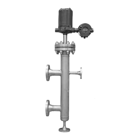
Page 16: Dimensions In Mm (Inches)
DIMENSIONS IN mm (inches) Top Mounted Side/bottom cage E81/E82 - J/K/L E83/E84 - J/K/L (10.75) (10.75) 367 (14.45) cast aluminium: 2 x M20 x 1,5 367 (14.45) (one entry plugged off) cast iron: 1 x 1" NPT stainless steel: 1 x M20 x 1,5 Level Range Level... - Page 17 DIMENSIONS IN mm (inches) Dimension A for all models Cage rating SG range 4 th digit Dimension A 0.23 - 0.54 J/A/M/D/Q 236 (9.29) 150 / 300 / 600 lbs 0.55 - 1.09 K/B/N/E/R 186 (7.32) PN 16 .. PN 100 1.10 - 2.20 L/C/P/F/T 186 (7.32)
- Page 18 MODEL IDENTIFICATION – UP TO 600 lbs BASIC MODEL NUMBER E 8 1 top mounted EZ Modulevel - Carbon steel construction E 8 2 top mounted EZ Modulevel - Stainless steel construction E 8 3 EZ Modulevel with side/bottom cage - Carbon steel construction E 8 4 EZ Modulevel with side/bottom cage...
- Page 19 MODEL IDENTIFICATION – FROM 900 lbs TO 2500 lbs BASIC MODEL NUMBER E 8 1 top mounted EZ Modulevel - Carbon steel construction E 8 2 top mounted EZ Modulevel - Stainless steel construction E 8 3 EZ Modulevel with side/bottom cage - Carbon steel construction E 8 4 EZ Modulevel with side/bottom cage...
-
Page 20: Service Policy
SERVICE POLICY Owners of Magnetrol products may request the return of a control; or, any part of a control for complete rebuilding or replacement. They will be rebuilt or replaced promptly. Magnetrol International will repair or replace the control, at no cost to the purchaser, (or owner) other than transportation cost if: a.
Need help?
Do you have a question about the Smart EZ Modulevel and is the answer not in the manual?
Questions and answers