
Related Manuals for Magnetrol Echotel 335


Summary of Contents for Magnetrol Echotel 335
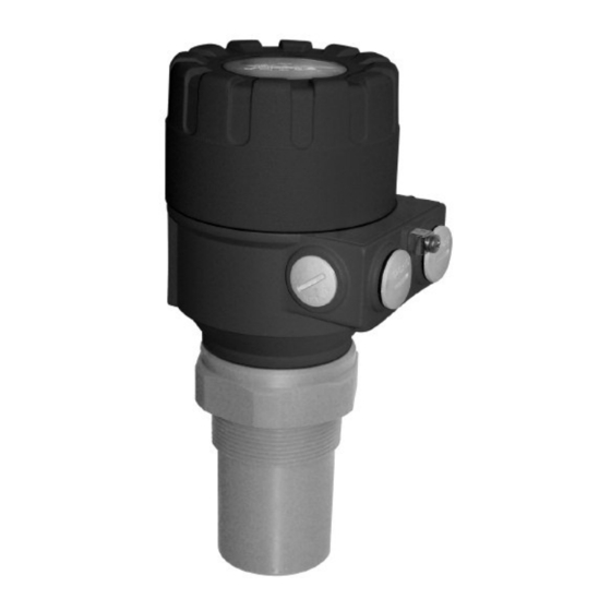
- Page 1 Echotel ® Model 335 Installation and Operating Manual Non-Contact Ultrasonic Transmitter For Level, Volume, and Open Channel Flow Measurement...
- Page 2 Notes contain information that augments or clarifies Magnetrol reserves the right to make changes to the an operating step. Notes do not normally contain product described in this manual at any time without actions.
-
Page 3: Table Of Contents
Echotel Model 335 Non-Contact Ultrasonic Transmitters Table of Contents 1.0 Installation 1.6.4 Performance Enhancement ......21 1.1 Unpacking ...............4 1.6.5 Volume Configuration .......26 1.2 Mounting and Application Considerations ....4 1.6.6 Open Channel Flow Configuration ...27 1.2.1 Position............4 1.6.7 Linearization Table........31 1.2.2 Orientation ..........4 1.6.8 Information Parameters......32 1.2.3 Temperature..........4 1.6.9 Open Channel Flow Head and Totalizers ..34... -
Page 4: Installation
Installation Caution: If equipment is used in a manner not specified by manufac- turer, protection provided by equipment may be impaired. Unpacking Unpack the instrument carefully. Inspect all units for damage. Report any concealed damage to carrier within 24 hours. Check the contents of the packing slip and purchase order. -
Page 5: Obstructions
1.2.4 Obstructions Ensure that no obstacles (e.g., fill pipes, ladders, bracing members, thermometers, etc.) protrude into the ultrasonic beam. Although one fixed object in the tank can be blocked out by appropriate programming, it is advised to avoid these obstructions. 1.2.5 Standpipes In applications where the material level may come into the deadband, the transducer must be mounted in a standpipe. -
Page 6: Electrostatic Discharge (Esd) Handling Procedure
Electrostatic Discharge (ESD) Handling Procedure Magnetrol electronic instruments are manufactured to the highest quality standards. These instruments use electronic components that may be damaged by static electricity pres- ent in most work environments. The following steps are recommended to reduce the risk of component failure due to electrostatic discharge. -
Page 7: Configuration
Configuration There are two methods of configuring the Echotel Model 335 transmitter: 1. QuickSet Configuration that allows an extremely basic level application configuration. 2. Complete Configuration which is used for most level applica- tions, and any volume or open channel flow configuration. 1.5.1 LCD Module The LCD module can be used to set any of the configura- tion parameters used with the 335 transmitter. - Page 8 The middle row of the LCD module consists of a 6-digit alphanumeric display of all data. Engineering units for the numeric data are printed above and below the LCD. Two pointers are used to indicate which units pertain to the display that is currently being viewed.
-
Page 9: Quickset Configuration
1.5.2 QuickSet Configuration Some very basic level applications can be easily set-up by using the QuickSet Configuration. Open channel flow, vol- ume, or more detailed level configuration is performed by using Section 1.6, Complete Configuration. The following eight parameters are set by using QuickSet: 1. -
Page 10: Basic Functions
1.5.3 Basic Functions The commands below set the basic functions of the 335 transmitter during QuickSet Configuration. Push Button Keys Function ENTER + DOWN Enter or exit QuickSet Configuration (press for 3 seconds) menu or DOWN Increase or decrease value of blinking digit, or scroll up/down to change parameters NEXT... - Page 11 NOTE: If no push buttons are pressed for 30 minutes, the transmitter will automatically return to the measurement mode, and oper- ate with the parameters entered during the last completed programming. To enter or exit the QuickSet Configuration menu press ENTER + DOWN keys for 3 seconds.
-
Page 12: Complete Configuration
Complete Configuration Open channel flow, volume, and more advanced level applications are configured using the Complete Configuration Menu. To enter (or exit from) this menu press the ENTER NEXT keys simultaneously for 3 seconds. While pro- gramming the 335 in this menu, the display will indicate: yy is the Parameter Register yy:xxxx xxxx is the Parameter Value... -
Page 13: Measurement Configuration Parameters
1.6.1 Measurement Configuration Parameters The following pages explain how to configure each of the parameters in the Complete Configuration. Since some of the Parameter Registers are not used by the 335, several parameters are skipped. Refer to Configuration Parameter Worksheet, Section 2.8, for a complete listing of all the parameters. - Page 14 P01: - ba Bar Graph and Measurement Mode Factory default value for P01 is: 11 The bar graph can be set at “0” to indicate the strength of the return echo, or to “1” to indicate the mA current out- put as a percentage of the span.
- Page 15 P02: - cba Calculation Units Factory default value for P02 is: 000 Engineering units for volume are selected in “b”, and units for open channel flow are selected using “b” and “c”. Metric or US for “b” is selected by the value of “c” in P00. The volume can also be displayed in units of weight by setting “b”...
- Page 16 P03: - a Displayed Values (Rounding & Decimal Position) Factory default value for P03 is: 0 Level and distance applications do not use P03 since the biggest number that can be displayed on the 6 digit LCD is 800 cm, or 315 inches. Displayed values for volume and open channel flow applications can become quite large, and for this reason it may be easier to read the LCD if rounding is used.
- Page 17 P04: Range Range is the maximum measuring distance. For level and volume applications this is the distance from the face of the transducer to the bottom of the tank. LEVEL = P04 (programmed) – DISTANCE (as measured from transducer face to liquid surface) Since the measurement accuracy of the 335 depends on a correct value of P04, it is critical to know the exact dis- tance between the face of the transducer and the bottom of...
- Page 18 P05: Deadband Factory default value for P05 is: 14.0 inches Non-contact ultrasonic transmitters require a “deadband” or “blind space” between the face of the transducer and the maximum liquid level. The minimum deadband for the Model 335 is 14" (35 cm), as shown in the drawing at left. The 335 will not process any ultrasonic signals within the Deadband (P05) deadband.
-
Page 19: Ma Current Output Settings
Open Channel Flow Applications Far end blocking is used in open channel flow applications to force a zero flow value when the level is below the chosen value. This allows the totalizer to stop recording flow when the level drops below the preset value. If the liquid level in the flume or weir falls below this value the 335 will: 1. -
Page 20: Spdt Relay Configuration
1.6.3 SPDT Relay Configuration P13: - a Relay Operation Factory default value for P13 is: 2 The 3-amp SPDT relay can be configured to be a wide differential level alarm, a diagnostic alarm for echo loss indication, or a pulsed relay for remote flow totalization. The 1-amp SPDT relay mimics the state of the 3-amp SPDT, but does not change state in the event of a power loss. -
Page 21: Performance Enhancement
1.6.4 Performance Enhancement Registers 20 through 33 can be used to enhance the per- formance of the Model 335 in specific applications. P20: - - - a Damping Factory default value for P20 is: 5 (60 seconds). Parameter register 20 can be used to reduce undesired fluctuations of the display and output, and enhance per- formance in turbulent applications. - Page 22 P24: - - - a Target tracking speed Factory default value for P24 is: 0. Tracking Speed Application Conditions Standard For most applications Fast For fast changing level Special Used only in special applications. The meas- uring window (see P25) becomes inactive, and the 335 responds instantly to any target.
- Page 23 P26: (m/hr) Vessel fill rate Factory default value for P26 is: 2000 m/hr (6562 ft/hr). P27: (m/hr) Vessel drain rate Factory default value for P27 is: 2000 m/hr (6562 ft/hr). Parameters P26 & P27 can be used to set the rate of filling or draining a vessel.
- Page 24 False target # 1 Factory default value for P29 is: 0.0 False target # 2 Factory default value for P30 is: 0.0 Up to two fixed objects in the tank can be blocked out if they are within the ultrasonic beam angle, and are creating false echoes.
- Page 25 Manual echo selection Factory default value for P33 is: 0 NOTE: Manual echo selection should not be used unless instructed to do so by the factory. Changing the default value of P33 will alter all measurements made by the Model 335. A "measuring window"...
-
Page 26: Volume Configuration
1.6.5 Volume Configuration Tank shape Factory default value for P40 is: 00 Volume can be displayed by entering the shape and dimen- sions of the tank. Most common tank shapes can be con- figured by using parameters P40 to P45. The Model 335 also has a 32-point linearization table (P47 &... -
Page 27: Open Channel Flow Configuration
1.6.6 Open Channel Flow Configuration Primary flow elements, formulas, and data Factory default value for P40 is: 00 Open channel flow measurement is accomplished by enter- ing the type of primary flow element being used in P40, and the flume or weir dimensions in P41 though P45. NOTE: P40 = 00 to P40 = 08 are not used for open channel flow applications. - Page 28 Reference distance Factory default value for P46 is: 0.00 Reference is the distance from the face of the transducer to the point where the flow rate becomes zero. This distance is different for each type of flume or weir. Measure the ref- erence distance as shown in the following pages of flumes and weirs, and enter into P46.
- Page 29 P40= 12 Palmer-Bowlus flume (rectangular) Palmer-Bowlus flumes make a transition from a circular bottom section to a raised trapezoidal throat, and then transition back to the circular bottom section. The range (P04) value is larger than the reference distance D/10 (P46) as shown at left.
- Page 30 P40= 16 Trapezoidal weir 0.0032 < Q[m /s] < 82 20 < P41[°] < 100 0.5 < P42[m] < 15 0.1 < h[m] < 2 /s] = 1.772*P42*h + 1.320*tg(P41/2)*h 2.47 The range (P04) value is larger than the reference distance (P46) as shown at left.
-
Page 31: Linearization Table
1.6.7 Linearization Table Linearization Linearization Table (Flow Example) Factory default value for P47 is: 0 Points Head (ft.) 0.00 0.00 The Model 335 offers a 32-point linearization table for 0.05 0.08 primary flow elements (open channel flow) or tank shapes 0.11 0.30 (volume) that are not in the standard software. -
Page 32: Information Parameters
The linearization table must start off with a value being assigned to zero level in the vessel or primary flow element. This zero level is assigned to data pair point 01 as “L: 000.0” and “r: xxxx” filled in with the volume, open channel flow, or level value corresponding to the zero level value. - Page 33 P64 – P66 indicate temperatures that the transducer has been exposed to: Parameter Units Description ° F or ° C Current temperature of the transducer Maximum temperature the transducer has ° F or ° C been exposed to Minimum temperature the transducer has °...
-
Page 34: Open Channel Flow Head And Totalizers
P75 Actual Deadband Distance P05 is used to set the deadband distance. P75 is a readout only parameter that shows the actual deadband value that the unit uses for diagnostic purposes. 1.6.9 Open Channel Flow Head and Totalizers Head of Flow Head is the “h”... -
Page 35: Simulation Mode
P81 Relay output test The state of the relay can be seen in P81 according to the table below and presence of a 0 or 1 in the display. The relay can be tested by pressing UP and DOWN switch P81 from a value of 1 to 0 and back. As the relay energizes and de-energizes the RELAY LED will turn on and off, and the resistance can be checked by a multimeter. -
Page 36: Additional Software Parameters
1.6.12 Additional Software Parameters P97 Software Code P97 stores the software revision number. P99 Password Protection P99 allows the entry of a password to protect all of the software configuration data. This provides protection against accidental (or intentional) re-programming of any parameters. -
Page 37: Diagnostic Error Codes
Diagnostic Error Codes There are a total of 13 different error codes that the Model 335 will produce depending on what type of mal- function occurs. Should this table not resolve the issue with the Model 335, please contact the factory for further assistance. -
Page 38: Reference Information
Reference Information Description The Model 335 ultrasonic transmitter performs level, volume, and open channel flow measurement of liquids. Measurement based on non-contact ultrasonic technology is especially suited for applications where no physical contact can be made to the surface of the liquid material to be measured. -
Page 39: Measurement Range Calculations
Measurement Range Calculations Ultrasonic non-contact transmitters are typically rated for a maximum range in ideal conditions. Experience has shown that maximum range must be reduced for certain factors. Although the maximum range rating is somewhat Beam spread conservative, each application must be evaluated for specific interference Beam spread conditions in the tank. -
Page 40: Velocity Of Sound In Gases Other Than Air
Velocity of Sound in Gases other than Air The velocity of sound through air is 1,128 ft/sec (343.8 m/sec) as indicated in P31. This velocity is used for all measurements made by the Model 335 transmitter. The table below contains the velocity of sound for various gases measured @ +68°... -
Page 41: Transmitter
2.6.2 Transmitter Supply voltage 85 to 255 VAC (2 VA) (Input power code A) (Input power code D) 20 to 28 VDC (3W) Output signal 4-20 mA isolated, 600 ohm load Fault detection Configurable 3 amp SPDT relay, LED, and 3.6 or 22 mA (NAMUR NE 43) Relays One, 3 Amp SPDT,... -
Page 42: Physical
2.6.4 Physical 3.75 (95) M20 x 1.5 (2) 5.8 (148) " NPT (2) 3.1 (80) 2" NPT 2.1 (54) Model Number BASIC MODEL NUMBER Integrally mounted transmitter with 50 kHz transducer, aluminum housing, polypropylene transducer ELECTRONICS HOUSING Cast aluminum dual compartment INPUT POWER 85 to 255 VAC 20 to 28 VDC... -
Page 43: Configuration Parameter Worksheet
Configuration Parameter Worksheet Par. Page Description Value Par. Page Description Value Application and Engineering Units not used Bar Graph and Measurement Mode not used Calculation Units not used Displayed Values (rounding) not used Range not used Deadband not used Far-end Blocking not used not used not used... - Page 44 No claims for misapplication, labor, direct or consequen- tial damage will be allowed. 5300 Belmont Road • Downers Grove, Illinois 60515-4499 • 630-969-4000 • Fax 630-969-9489 • www.magnetrol.com 145 Jardin Drive, Units 1 & 2 • Concord, Ontario Canada L4K 1X7 • 905-738-9600 • Fax 905-738-1306 Heikensstraat 6 •...
Need help?
Do you have a question about the Echotel 335 and is the answer not in the manual?
Questions and answers