
Related Manuals for Magnetrol A10


Summary of Contents for Magnetrol A10
- Page 1 Displacer Type Installation and Operating Manual Liquid Level Proof-er ® Switches...
- Page 2 Magnetrol will repair or replace the control at no cost to materials. In this manual, a caution box indicates a the purchaser (or owner) other than transportation.
-
Page 3: Table Of Contents
4.4.1 Displacer Replacement Parts.....33 4.1.1 Check switch mechanism......10 4.5 Model Numbers ..........34 4.1.2 Test control’s performance ......11 4.5.1 A10 & A15 Single Switch Models ....34 4.1.3 Proof-er ............12 4.5.2 B10 & B15 Dual Switch Models ....36 4.2 Agency Approvals ..........12 4.5.3 C10 &... -
Page 4: Introduction
1.0 Introduction Displacement type level switches offer the industrial user a wide choice of alarm and control configurations. These units utilize simple buoyancy principle and are well suited for simple or complex applications. Principle of Operation 1.1.1 Displacer Controls The design of displacer operated level switches is based upon the principle that a magnetic field will not be affected by non- magnetic materials such as 316 stainless steel. -
Page 5: Installation
Installation Caution: If equipment is used in a manner not specified by manu- facturer, protection provided by equipment may be impaired. Unpacking Top mounting displacer units are shipped from the factory with the displacer and cable assembly removed from the head assembly and packed separately in the same container. -
Page 6: Wiring
Caution: Before attaching Magnetrol control to tank or vessel, using a level, check to see that tank mounting flange is within 3° of horizontal in all directions. Proper operation of the con- trol depends on the switch housing being plumb. - Page 7 NOTE: On high temperature applications above +250° F (+121° C), INTERNAL INTERNAL CIRCUIT CIRCUIT (LEFT) (RIGHT) high temperature wire should be used between control and SWITCH SWITCH first junction box located in a cooler area. On non-hazardous applications, flexible conduit may be used between the con- trol and the first junction box.
-
Page 8: Preventive Maintenance
11. Check cover to base fit to be certain gasketed joint is tight. INTERNAL A positive seal is necessary to prevent infiltration of mois- LOAD CIRCUIT Close on low level (NC) ture laden air or corrosive gasses into switch housings. COMMON (C) Close on high level (NO) LOAD... -
Page 9: What To Avoid
4. Vibration may sometimes cause terminal screws to work loose. Check all terminal connections to be certain that screws are tight. 5. On units with pneumatic switches, air (or gas) lines sub- jected to vibration, may eventually crack or become loose at connections causing leakage. -
Page 10: Reference Information
Reference Information Troubleshooting Usually the first indication of improper operation is failure of the controlled equipment to function, i.e., pump will not start (or stop), signal lamps fail to light, etc. When these symptoms occur, whether at time of installation or during routine service thereafter, check the following potential external causes first. -
Page 11: Test Control's Performance
4.1.2 Test control’s performance 1. Reconnect power supply and carefully actuate switch mechanism manually, using a non-conductive tool on elec- trical switch mechanism, to determine whether controlled equipment will operate. Caution: With electrical power on, care should be taken to avoid contact with switch leads and connections at terminal block. -
Page 12: Proof-Er
4.1.3 Proof-er If the Proof-er is not functioning properly, listed below are potential problems and corrective action. 1. Proof-er does not return to the down position after it is activated. C USE REMEDY Defective return spring. Replace Spring. Buildup between the shaft Clean Proof-er to and housing restricting remove buildup. -
Page 13: Specifications
➀ With housing drain, CSA drops Group E and FM drops Group C. ➁ Models B10 and B15 with “HS” switches and all Model C10 and C15 are not ATEX approved. ➂ IEC Installation Instructions: The cable entry and closing devices shall be Ex d certified suitable for the conditions of use and correctly installed. -
Page 14: Model A10 Dimensional Data And Actuating Levels
Specifications 4.3.3 Model A10 Dimensional Data and Actuating Levels Inches (mm) Model A10 Outline Dimensions Displacer Type Threaded Mounting Flanged Mounting Displacer Porcelain 2.56 (65) 7.25 (184) 3.62 (91) Type Stainless Steel 2.50 (63) 9.00 (228) 4.50 (114) or Karbate 5.00... -
Page 15: Model A15 Dimensional And Actuating Levels
Specifications 4.3.4 Model A15 Dimensional Data and Actuating Levels Inches (mm) Model A15 Outline Dimensions Displacer Type Threaded Mounting Flanged Mounting Displacer Porcelain 2.56 (65) 7.25 (184) Type Stainless Steel 2.50 (63) 9.00 (228) or Karbate 5.62 242.00 7.62 244.00 Porcelain (142) (6146) -
Page 16: Model B10 Dimensional Data
Specifications 4.3.5 Model B10 Dimensional Data Inches (mm) Model B10 Model B10 with displacer arrangements 1 and 2 Outline Dimensions Displacer Type Threaded Mounting Flanged Mounting Displacer Porcelain 2.56 (65) 10.04 (255) 5.02 (127) Type Stainless Steel 2.50 (63) 12.00 (304) 6.00 (152) or Karbate 4.88 242.00... -
Page 17: Model B10 Actuating Levels
Specifications 4.3.6 Model B10 Actuating Levels Inches (mm) Actuation Actuation Upper Switch Upper Actuation Switch Actuation Lower Switch Lower Switch Actuation Actuation Model B10 Model B10 Displacer Arrangement 1 Displacer Arrangement 2 Actuation Actuation Actuation Upper Upper Switch Switch Upper Switch Actuation Actuation... - Page 18 Specifications 4.3.6 Model B10 Actuating Levels (cont.) Inches (mm) B10 Standard actuating levels and liquid specific gravity with displacer arrangement 1 Displacer Liquid Type Temp. ° F Level 1.08 – 1.12 1.13 – 1.17 1.18 – 1.27 1.28 – 1.30 1.31 –...
- Page 19 Specifications 4.3.6 Model B10 Actuating Levels (cont.) Inches (mm) B10 Standard actuating levels and liquid specific gravity with displacer arrangement 1 (cont.) Displacer Liquid Type Temp. ° F Level 0.50 – 0.58 0.59 – 0.71 0.72 – 0.79 0.80 – 0.85 0.86 –...
- Page 20 Specifications 4.3.6 Model B10 Actuating Levels (cont.) Inches (mm) B10 Standard actuating levels and liquid specific gravity with displacer arrangement 2 (cont.) Displacer Liquid Temp. Level 1.08 – 1.12 1.13 – 1.17 1.18 – 1.27 1.28 – 1.30 1.31 – 1.39 1.40 –...
- Page 21 Specifications 4.3.6 Model B10 Actuating Levels (cont.) Inches (mm) B10 Standard actuating levels and liquid specific gravity with displacer arrangement 2 Displacer Liquid Type Temp. ° F Level 0.50 – 0.58 0.59 – 0.71 0.72 – 0.79 0.80 – 0.85 0.86 –...
- Page 22 Specifications 4.3.6 Model B10 Actuating Levels (cont.) Inches (mm) B10 Standard actuating levels and liquid specific gravity with displacer arrangements 3, 4, and 5 (cont.) Displacer Liquid Temp. Level 1.08 – 1.12 1.13 – 1.17 1.18 – 1.27 1.28 – 1.30 1.31 –...
- Page 23 Specifications 4.3.6 Model B10 Actuating Levels (cont.) Inches (mm) B10 Standard actuating levels and liquid specific gravity with displacer arrangements 3, 4, and 5 Displacer Liquid Temp. Level 0.50 – 0.58 0.59 – 0.71 0.72 – 0.79 0.80 – 0.85 0.86 –...
-
Page 24: Model B15 Dimensional Data
Specifications 4.3.7 Model B15 Dimensional Data Inches (mm) Model B15 Outline Dimensions Displacer Type Threaded Mounting Flanged Mounting Displacer Porcelain 2.56 (65) 7.25 (184) 5.02 (127) Type Stainless Steel 2.50 (63) 10.50 (266) 6.00 (152) or Karbate 5.50 243.00 7.50 245.00 Porcelain (139) -
Page 25: Model B15 Actuating Levels
Specifications 4.3.8 Model B15 Actuating Levels Inches (mm) B15 Standard actuating levels and liquid specific gravity Liquid 0.70 0.80 Displacer Temp. Type ° F Stainless +100 9.50 (241) 5.00 (127) 4.90 (124) 1.30 (33) 7.60 (193) 3.70 (93) 4.30 (109) 1.10 (27) Steel or Karbate... -
Page 26: Model C10 Dimensional Data
Specifications 4.3.9 Model C10 Dimensional Data Inches (mm) Model C10 with displacer arrangements D and F Model C10 with all displacer arrangements Outline Dimensions Displacer Type Threaded Mounting Flanged Mounting Displacer 2.56 14.44 5.02 3.62 Porcelain Type (65) (367) (127) (91) Stainless Steel 2.50... -
Page 27: Model C10 Actuating Levels
Specifications 4.3.10 Model C10 Actuating Levels Inches (mm) Actuation Actuation Upper Switch Upper Switch Actuation Actuation Middle Switch Middle Switch Actuation Actuation Lower Lower Switch Switch Actuation Actuation Model C10 Model C10 Displacer Arrangement A Displacer Arrangement B Actuation Actuation Actuation Upper Switch... - Page 28 Specifications 4.3.10 Model C10 Actuating Levels (cont.) Inches (mm) C10 Standard actuating levels and liquid specific gravity with displacer arrangements A, B, and C 0.58 0.60 0.70 0.80 Displacer Liquid Type Temp. ° F 2.50 2.20 2.20 2.00 2.30 2.00 1.90 1.70 Porcelain...
- Page 29 Specifications 4.3.10 Model C10 Actuating Levels (cont.) Inches (mm) C10 Standard actuating levels and liquid specific gravity with displacer arrangements E and G 0.58 0.60 0.70 0.80 Displacer Liquid Type Temp. ° F 2.50 2.20 5.80 1.90 2.30 2.00 5.50 2.10 Porcelain +100...
-
Page 30: Model C15 Dimensional Data
Specifications 4.3.11 Model C15 Dimensional Data Inches (mm) Model C15 OUTLINE DIMENSIONS Displacer Type Threaded Mounting Flanged Mounting Displacer 2.56 7.25 6.42 5.02 Porcelain Type (65) (184) (163) (127) Stainless Steel 2.50 9.00 7.50 6.00 7.75 245.00 9.75 247.00 Porcelain or Karbate (63) (228) -
Page 31: Model C15 Actuating Levels
Specifications 4.3.12 Model C15 Actuating Levels Inches (mm) C15 Standard actuating levels and liquid specific gravity Liquid 0.65 0.70 0.80 Displacer Temp. Type ° F 6.20 1.40 5.30 1.00 3.80 0.90 Porcelain 0 to +130 — — — — — —... -
Page 32: Proof-Er Replacement Parts
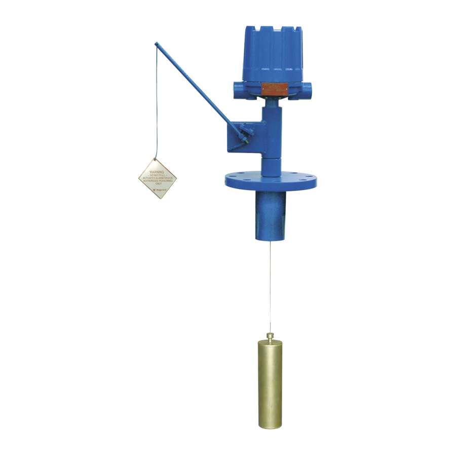
Specifications 4.3.13 Proof-er Dimensional Data Inches (mm) TyPICAL PrOOF-Er INSTALLATION WITH vErSA FLANGE 5.93 (151) 14.62 (371) Minimum clearance 4.29 (109) required for actuation 1" NPT 30' (9 m) Cable standard Optional flange 1 ⁄2 " NPT 20' (6 m) Cable standard vErSA FLANGE ASSEMBLy PArT NUMBEr 089-5207-001... -
Page 33: Replacement Parts
➀ Replacement arts Item No. Description B10/B15 C10/C15 ➁ Enclosing Tube Kit Standard 089-5933-007 089-5933-001 089-5933-007 089-5959-003 316 SS 089-5933-008 089-5933-002 089-5933-008 089-5959-020 E-Tube Gasket 012-1204-001 ➂ ➃ Spring and Stem Kit Standard 089-5327-001 089-5325-001 ➃ 316 SS 089-5328-001 089-5326-001 Body Bushing 089-5707-001 Flange and Spring Protector... -
Page 34: Model Numbers
Model Numbers 4.5.1 A10 & A15 Single Switch Models PArT NUMBEr CODE AND SPECIFIC GrAvITy LIMITS* Liquid Part Number Description Temp. Series A thru E, J and K Switches Code °F °C Porcelain Stainless Steel Karbate 0.60 to 1.20 0.60 to 1.20 0.60 to 1.20... - Page 35 SPDT Hermetically Sealed Snap (260) DPDT Switch w/Terminal Block Series 8 SPDT Hermetically Sealed (260) Snap Switch DPDT PNEUMATIC SWITCH MECHANISM AND ENCLOSUrE FOr MODELS A10 AND A15 ➇ Maximum Maximum Bleed Switch Supply Process Orifice A10 Codes A15 Codes...
-
Page 36: B10 & B15 Dual Switch Models
Model Numbers 4.5.2 B10 & B15 Dual Switch Models Note: Each B10 instrument is factory calibrated to operate on a given specific gravity within the minimum and PArT NUMBEr CODE AND SPECIFIC GrAvITy LIMITS* maximum values listed. Liquid Part Number Description Temp. - Page 37 Model Numbers 4.5.2 B10 & B15 Dual Switch Models (continued) ➇ ELECTrIC SWITCH MECHANISM AND ENCLOSUrE FOr MODELS B10 AND B15 Switch Enclosure Max. ➉ NEMA 4X/7/9 Switch Description ➈ Process Temp. Class I, Div. 1, Class I, Div. 1, ATEX °...
-
Page 38: C10 & C15 Triple Switch Models
Model Numbers 4.5.3 C10 & C15 Triple Switch Models PArT NUMBEr CODE AND SPECIFIC GrAvITy LIMITS** Liquid Part Number Description Temp. Series A thru E, J and K Switches Code °F °C Porcelain Stainless Steel Karbate 0.65 to 1.20 0.58 to 1.20 0.58 to 1.20 Wide Differential, 3 switches 0.95 to 1.10... - Page 39 Model Numbers 4.5.3 C10 & C15 Triple Switch Models (continued) ELECTrIC SWITCH MECHANISM AND ENCLOSUrE ➅ FOr MODELS C10 AND C15 Aluminum Polymer Coated Switch Enclosure ➄ NEMA 4X/7/9 Maximum ➃ Switch Description Process Temp. Three Class I, Div. 1, Aluminum Aluminum Aluminum...
- Page 40 ASSUrED QUALITy & SErvICE COST LESS Service Policy Return Material Procedure Owners of Magnetrol controls may request the return of a So that we may efficiently process any materials that are control or any part of a control for complete rebuilding or returned, it is essential that a “Return Material...
Need help?
Do you have a question about the A10 and is the answer not in the manual?
Questions and answers