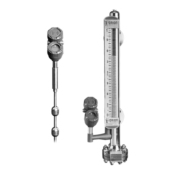
Magnetrol JUPITER JM4 Safety Manual
Magnetostrictive level transmitter; sil
Hide thumbs
Also See for JUPITER JM4:
- Operating manual (124 pages) ,
- Installation and operating manual (76 pages) ,
- Installation and operating manual (68 pages)
Table of Contents
Advertisement
Quick Links
Download this manual
See also:
Operating Manual
Advertisement
Table of Contents

Summary of Contents for Magnetrol JUPITER JM4
- Page 1 Model JM4 Software v1.x SIL Safety Manual Magnetostrictive Level Transmitter This manual complements and is intended to be used with the Orion Instruments® Jupiter® Model JM4 Magnetostrictive Level Transmitter Installation and Operating Manual (Bulletin ORI-650).
-
Page 2: Table Of Contents
Jupiter® Model JM4 Magnetostrictive Transmitter SIL Safety Manual Table of Contents 5.5.2 Configuration ..... . . 7 1.0 Introduction 1.1 Product Description ......3 5.5.3 Write Protecting/Locking. -
Page 3: Introduction
NOTE: For Safety Instrumented Systems usage, it is assumed that Table 1 the 4-20 mA output is used as the primary safety variable. JUPITER JM4 Model Number The analog output for the Model JM4 meets the NAMUR NE 43 standard (3.8 mA to 20.5 mA usable). The transmitter... -
Page 4: Level Measuring System
• The only unsafe mode is when the unit is reading an incorrect Unit level within the 4–20 mA range (> ±2% deviation). • MAGNETROL defines a safe failure as one in which the 4–20 mA current is driven out of range (i.e., less than 3.8 mA or greater than 21.5 mA). -
Page 5: Mean Time To Restoration (Mttr)
Overvoltage Category II is a local level, covering appliances, por- table equipment, etc., with smaller, transient overvoltages than those characteristic of Overvoltage Category III. This category applies from the wall plug to the power-supply isolation barrier (transformer). As the typical plant environment is Overvoltage Category II, most equipment evaluated to the requirements of IEC/EN 61010 are considered to belong in that classification. -
Page 6: Environmental
5.1.2 Environmental Refer to Installation and Operating Manual ORI-650 for envi- ronmental limitations. 5.1.2.1 Storage The device should be stored in its original shipping box and not be subjected to temperatures outside the storage temperature range of -50 to +185 °F (-46 to +85 °C). Installation Refer to the Model JM4 Installation and Operating Manual ORI-650 for complete installation instructions. -
Page 7: Configuration
5.5.2 Configuration Ensure the parameters have been properly configured for the application and probe. Special consideration should be given to the following configuration parameters: FAULT: DO NOT choose HOLD for this parameter as a Fault will not be annunciated on the current loop. BLOCKING DISTANCE: This value MUST be zero for SIL applications. -
Page 8: Troubleshooting
5.8.2 Troubleshooting Report all failures to the MAGNETROL technical support department. Refer to the Model JM4 Installation and Operating Manual ORI-650 for troubleshooting device errors. • The SIL Proof Test provides a reliable indication when mainte- nance is required. • Firmware can be upgraded only by factory personnel. - Page 9 Step Action Bypass the PLC or take other action to avoid a false trip. Remove power from the Unit. (This clears any potential soft RAM errors.) Inspect the Unit in detail outside and inside for physical damage or evidence of environmental or process leaks. a.) Inspect the exterior of the unit housing.
- Page 10 Step Action Use the “DIAGNOSTICS” menu to observe the present Echo Curve and document typical per- formance values. Confirm that the ECHO Waveform is normal. The ECHO curve is dependent on the probe used and the level of the process on the probe. It is recommended that a typical ECHO curve be saved at commissioning.
-
Page 11: Appendices
Appendices SIL Declaration of Conformity Functional safety according to IEC 61508/IEC 61511. Orion Instruments, 2105 Oak Villa Boulevard, Baton Rouge, Louisiana 70815, declares as the manufacturer that the level transmitter: Magnetostrictive (4-20 mA) Model JM4-511x-xxx is suitable for the use in safety instrumented systems according to IEC 61511-1, if the safety instructions and following parameters are observed: Product... - Page 12 ORI-652 Jupiter Model JM4 Magnetostrictive Transmitter – SIL Safety Manual ®...
-
Page 13: Specific Model Jm4 Values
7.3 Specific Model JM4 Values Specific Model JM4 JUPITER Product Model JM4-511x-xxx SIL 2 Single Float 93.1% 1.97E-03 Dual Float 91.9% 1.96E-03 Annually Proof Test Interval (refer to PFD Graph below) PFD Graph The resulting PVD Graph generated from the exSILentia tool for a proof test interval of one year is displayed below. \PFD value for a single Model JM4-511x-xxx (one float) with proof test intervals of one year. -
Page 14: Report: Lifetime Of Critical Components
value for a single Model JM4-511x-xxx (two floats) with proof test intervals of one year. It is the responsibility of the Safety Instrumented Function designer to perform calculations for the entire SIF. value needs to be ≥ 10 and < 10 For SIL 2 applications, the PFD This means that for a SIL 2 application, the PFD for a 1-year Proof... -
Page 15: References
It is the responsibility of the end user to maintain and operate the Model JM4-511x-xxx per manufacturer’s instructions. Fur- thermore, regular inspection should indicate that all components are clean and free from damage. When plant experience indicates a shorter lifetime than indicat- ed here, the number based on plant experience should be used. - Page 16 Disclaimer The SIL values in this document are based on an FMEDA analysis using exida’s SILVER Tool. MAGNETROL accepts no liability whatsoever for the use of these numbers for the correctness of the standards on which the general calculation methods are based ASSURED QUALITY &...


Need help?
Do you have a question about the JUPITER JM4 and is the answer not in the manual?
Questions and answers