Advertisement
Quick Links
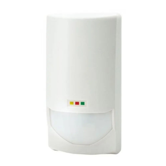
HIGH-END INDOOR DETECTOR
HIGH-END INDOOR DETECTOR
OPTiMAL series
OPTiMAL series
OPTiMAL series provides a comprehensive product lineup from
standard to high-end model which suitable for any applications.
In addition to providing high reliable basic performance with our unique
infrared detection technology, the combination of active IR and dual
technology provides outstanding anti-masking reliability.
OPTiMAL series provides compliance with EN50131-1.
•OML-ST
: standard model with PIR
•OML-AM
: OML-ST with active IR anti-masking method
•OML-DT
: standard model with PIR and microwave
•OML-DAM : OML-DT with active IR anti-masking method
QUALITY ASSURANCE
N219
1
INSTALLATION HINTS
Warning
INSTALLATION INSTRUCTIONS
Warning
Caution
1m
No.59-1484-0
2
KNOCKOUTS
Wiring knockout
Corner
mount
knockout
(Grade 2)
(Grade 3)
(Grade 2)
Caution to release the unit base>>
(Grade 3)
3
DETECTION AREA
TOP VIEW
SIDE VIEW
LONG RANGE
IMPORTANT>>
- Set the DETECTION MODE switch "STD" position (see 6-B)
- Set the PIR SENSITIVITY "HIGH" with detection range over 20m (67ft.)
(see 6-H)
TOP VIEW
0
(m)
2
1
0
1
2
0
SIDE VIEW
0
(m)
0
1.8
2.4
3.0
0
Down Zone
When using Down Zone detection, peal off the lens surface sticker.
When using a bracket>>
Choose the appropriate
Mounting
mounting holes for corner or
knockout
wall fixing.
When using a wall tamper>>
Corner
mount
Use the knockout for a wall
knockout
tamper. If the main unit if
prised off the wall, the grey
section will break away and
stay on the wall and the
Wall
tamper switch will operate.
tamper
knockout
When installing on a plaster
board wall or other soft
note) Mount both knockouts
material, pre cut out the grey
with accessory screws
area from the back plate.
1
Pull up the base
0
10
20
30
(m)
7
5
0
5
7
0
5
0
10
20
30
(m)
0
1.8
2.4
3.0
0
5
Down Zone
When using Down Zone detection, peal off the lens surface sticker.
(when using CL-80N) (OML-ST only)
10
20
30
40
50
5
10
15
10
20
30
40
50
5
10
15
2
Pull out
40
50(ft)
(ft)
20
MW
PIR
10
0
10
20
10
15(m)
MW
40
50(ft)
0 (ft)
PIR
6
8
10
10
15(m)
60
70
80(ft)
5(ft)
0
5
20
24(m)
60
70
80(ft)
0 (ft)
6
8
10
20
24(m)
Advertisement

Subscribe to Our Youtube Channel
Related Manuals for Optex OML-ST


Summary of Contents for Optex OML-ST
- Page 1 •OML-ST : standard model with PIR (Grade 2) area from the back plate. •OML-AM : OML-ST with active IR anti-masking method (Grade 3) •OML-DT : standard model with PIR and microwave (Grade 2) Caution to release the unit base>>...
- Page 2 When connecting to a control panel that supports the EOL technique LED ON/OFF Dip switch Three types of signals - ALARM OUTPUT, TROUBLE OUTPUT, OML-ST OML-AM OML-DT OML-DAM and TAMPER - can be recognized through the combination of the LED can be set “ON” or “OFF”.
- Page 3 ANTI-MASKING SENSITIVITY MICROWAVE CONTROL Dip switch Dip switch OML-ST OML-AM OML-DT OML-DAM OML-ST OML-AM OML-DT OML-DAM When an object is placed close to the lens surface, When this switch is set to ON the microwave can be for a period of more than 10 seconds then the PIR...
- Page 4 PIR detection Green lights required by Article 6.3 of the R&TTE Directive, 1999/5/EC. MW detection Yellow lights The Optex OPTiMAL series are in conformity with all essential Power supply abnormality Red blinks requirements of the R&TTE Directive (1999/5/EC). This equipment Anti-Masking Yellow&green blink...
Need help?
Do you have a question about the OML-ST and is the answer not in the manual?
Questions and answers