Table of Contents
Advertisement
Advertisement
Table of Contents

Related Manuals for MAGINON IPC-1A


Summary of Contents for MAGINON IPC-1A
-
Page 3: Preface
Dear customer, Congratulations on purchasing a high quality MAGINON® product. You have acquired a modern WiFi Network Camera with excellent technical features and respective accessories, which is particularly easy to operate. Please study this information in detail observing, in particular, the safety instructions. -
Page 4: Table Of Contents
Default user data of the WiFi Network Camera Note: admin user account when using the WiFi Network Camera for the first time! Uer name: admin Password: no password has been set! New password: _______________________ 2. Contents Preface 1. Contents of box 2. - Page 5 7.11. Alarm settings 7.12. Camera head settings 7.13. Resetting 7.14. Restarting 8. Use with mobile devices 8.1. Activation via Browser 8.2. Instructions for App “Maginon IPC Viewer” 9. FCC statement 10. Disposal 11. Warranty and service 12. Technical specification 13. Index...
-
Page 6: Hazard, Safety And Warning Notices
3. 3. Hazard, safety and warning notices Incorrect use of the camera and accessories can be dangerous for you and others and can damage or destroy the WiFi Network Camera. We therefore ask you to read and strictly observe the following Hazard, safety and warning notices. Intended use This WiFi Network Camera is solely designed for the surveillance of internal areas. - Page 7 Eletrical hazard Switch off camera if a foreign body or liquid has entered the camera. Wait until completely dry, as there is a danger of fire and electrocution. Switch off camera if camera has been dropped or housing is damaged, as there is a danger of fire and electrocution.
- Page 8 Do not place any open ignition sources onto or close to the camera. Damage to the electronics or housing caused by external influences, such as electric shocks, falls or others are not covered by the warranty and shall thus be charged for. Legal information This WiFi Network Camera is designed solely for internal monitoring.
-
Page 9: Preparation
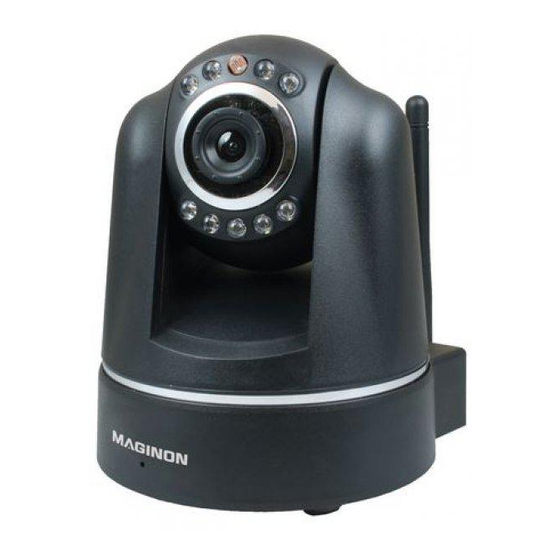
4. Preparation 4.1. Part names 1. MAGINON WiFi Network Camera 5. Alarm connecting terminal IPC-1A 6. Installation material (not shown) 2. Wall bracket with stand fastening 7. Software CD (not shown) 3. LAN cable 8. Instruction Manual (not shown) 4. Power supply... -
Page 10: Views Of Wifi Network Camera
4.2. Views of WiFi Network Camera 90° 270° 1. Lens 6. Network connection (LAN) 2. Infrared LED 7. Alarm connection (In/Out) 3. Sensor 8. Power supply connection (DC 5V) 4. WLAN connection 9. Reset button 5. Audio connection (no function) 10. -
Page 11: Installing The Wifi Network Camera
4.3. Installing the WiFi Network Camera Using the supplied wall bracket, the WiFi Network Camera can be installed at a fixed location. Note: as this could cause interference. If interfere is detected, test camera at another location first. into the lens. 4.3.1 Attaching the wall bracket Hold the plate of the wall bracket against the surface of the selected place of installation and, using a pencil, mark two holes on the surface through the holes in the plate. - Page 12 4.3.3 Completing the camera installation Connect the WiFi Network Camera to the power supply and then connect the power supply to a mains socket.
-
Page 13: Setting Up The Wifi Network Camera
5. Setting up the WiFi Network Camera 5.1. Introduction The below diagram shows how to integrate the WiFi Network Camera in your existing home network and how it can be accessed via the Internet. The router provides the local network in your home and also provides access to the Internet. The WiFi Network Camera is therefore connected to the router using a network cable or via WiFi. -
Page 14: System Requirements
5. Set up port forwarding in the router to allow the WiFi Network Camera to be accessed from the Internet (see section 5.8, Internet access). 6. Install the App “Maginon IPC Viewer” for Smartphones and TabletPCs (see section 8, Use with mobile devices). -
Page 15: Hardware Installation
5.3. Hardware installation Using an existing router, the WiFi Network Camera is integrated in an existing computer network. A router is generally a device connecting your computer or a local network to the Internet. To carry out these basic settings on the WiFi Network Camera, the camera must first be connected directly to the router using the supplied network cable. -
Page 16: Software Installation
The following selection menu should then appear. If the menu does not start automatically, select My Computer on your computer and open the CD/DVD drive “Maginon IP Camera” by clicking on it with the mouse. Start the CDMenu/ CDMenu.exe. program by double clicking on the option. -
Page 17: Connecting The Wifi Network Camera
5.5. Connecting the WiFi Network Camera Ensure that the WiFi Network Camera is connected to the router via the network cable and is connected to the mains (see section 5.3, Hardware installation). Next, open the program supra IPCam Config. In the program select “Start search” to view a list of reachable WiFi Network Cameras. From the list select the WiFi Network Camera you wish to set up or call up. - Page 18 The WiFi Network Camera is automatically set up in the network if the option “Use DHCP” has been activated and the used router also supports DHCP and the function has been activated. If under address an address other than 0.0.0.0 appears, the automatic network set up of the WiFi Network Camera was successful.
-
Page 19: Installation On Mac Os
This IP address allows you to access the configuration data of the router. You will then need the IP address of the WiFi Network Camera from the settings data. This address allows you to open the configuration side of IPC-1A and adjust the settings of the WiFi Network Camera. - Page 20 Now change to the “TCP/IP” page where you can find the IP address of your router behind “Router”. In the below example this is address 192.168.16.1. Determining the IP address of the WiFi Network Camera Open the Internet Browser Safari and enter the IP address of your router as the target address.
- Page 21 Please note that the configuration of your router may differ from the shown example. In the list, the WiFi Network Camera is shown as “ipcam_xxx”. In the above example this is “ipcam_006E060241 B6“. Next to it is the IP address of the WiFi Network Camera (here: 192.168.1.113).
-
Page 22: Setting Up A Wireless Connection
5.7. Setting up the wireless connection The WiFi Network Camera can be connected to the router using a wireless connection via WLAN. To set up this wireless connection with the WiFi Network Camera it must be connected to the router via the network cable. Using the supra IPCam Config program, search for the WiFi Network Camera in the network and start the log in page of the... -
Page 23: Internet Access
5.8. Internet access In the previous sections the WiFi Network Camera was set up in such a way that the camera can be accessed within your local network. This section now explains how the surveillance camera can be accessed via the Internet. To be able to call up the WiFi Network Camera via the Internet you first of all require the Internet address (public IP address) of your Internet access. - Page 24 If an error message appears after calling up the WiFi Network Camera via the public IP address from outside the local network, access to the WiFi Network Camera is probably blocked by the Firewall integrated in your router. In this case, the settings of the router must be changed in such a way that access to the camera via the Internet is permitted.
- Page 25 In the shown example, two WiFi Network Cameras are connected to the router, one camera named IPCamera1 with the local network address 192.168.1.110 and a second camera with the name IPCamera2 and the local network address 192.168.1.111. We are now setting the external port 81 as access for the WiFi Network Camera IPCamera1. TCP and UDP protocols may be selected but only TCP is required.
-
Page 26: Using The Wifi Network Camera
6. Using the WiFi Network Camera 6.1. Activating the WiFi Network Camera First open your Browser window (Internet Explorer, Firefox, Opera, Google Chrome, Safari or similar). Enter the IP address of the WiFi Network Camera. If you wish to access the WiFi Network Camera from a computer connected to the same network, you can also enter the local network address. -
Page 27: Controlling The Wifi Network Camera
6.2. Controlling the WiFi Network Camera Various elements and options are available for controlling the camera. Below the camera image control elements directly controlling the alignment of the camera head, are provided as well as some basic camera settings. What operating elements are available and what settings may be changed depend on the level of access assigned to the user account. - Page 28 The center Calibrate button, serves to realign the camera head. Click on the button once and leave the mouse button on the button until the camera head no longer moves. A calibration should be carried out if the camera head has been moved manually, causing the stored positions to no longer work.
- Page 29 6.2.3. Camera image settings Specify the camera image settings in the View window. Resolution: This option allows you to select whether the image of the WiFi Network Camera is shown in 640 x 640 pixels or 320 x 240 pixel resolution. Light frequency: Where the WiFi Network Camera is used in a room lit by neon lighting, the frequency of the local power grid (50 or 60 Hz) can be set under this option.
-
Page 30: Settings
7. Settings The next sections provide an overview of all setting options of the WiFi Network Camera. In case of problems during installation or use of the WiFi Network Camera, information is provided below as regards the different options. In the Internet Browser, open the access to the WiFi Network Camera (see section 6.1) and log in via a user account with Administrator rights. -
Page 31: Camera Name
7.2. Camera name You can assign a name to the WiFi Network Camera, for instance to make it easier to find the camera in the network or for a clear assignment where several WiFi Network Camera are used. For this purpose select “Camera name” from the bottom menu bar (second symbol). Enter the desired name for the WiFi Network Camera in the text field and click on “Save”. -
Page 32: Date And Time
7.3. Date and time In this option enter the time zone in which the WiFi Network Camera is located and whether the date and time should be automatically updated by a so called NTP server (time server). The correct time is, for instance, required for planning the time for alarms or FTP transfers. Current date and time: This option shows the date and time as stored in the surveillance camera. -
Page 33: Uesr Accounts
7.4. User accounts Up to 8 user accounts can be set up for the WiFi Network Camera. The user account then allows access to the WiFi Network Camera. The WiFi Network Camera is supplied with the user account “admin”, not requiring any password. -
Page 34: Network Settings
7.5. Network settings Network settings must be set up to connect the WiFi Network Camera to an existing network or a router. Use DHCP: Click this option where a new device (Client) can be automatically connected to your network. All required data is then directly obtained from the server or router. Port of Web platform: Connections in a network are provided via so called ports. - Page 35 Remove the check mark from “Use DHCP” if your router does not support an automatic connection of new devices to your router. Several new input fields will then become available in which you have to manually enter the access data of your network. The required data can generally be called up on the computer via the network properties or can be obtained from the System...
-
Page 36: Wireless Settings
7.6. Wireless settings In case of a wireless connection of the WiFi Network Camera to a network via WLAN (Wireless LAN), the necessary settings can be entered under this option. In this case, select menu option ”Wireless settings”. Using wireless LAN: Check this option if you intend to use a wireless connection to the network. - Page 37 Region: Depending on the region, different channels are not supported. Consequently, select the region in which the WiFi Network Camera is installed. Encryption: Within the wireless network data is in most cases transmitted in encrypted form to prevent third parties accessing the data. Specify what type of encoding is used in your WLAN network.
-
Page 38: Upnp Settings
7.7. UPNP settings Universal Plug and Play (UPnP) is used for controlling devices irrespective of their make via an IP based network. Where UPnP is supported by the router and is also activated, the required Firewall settings are automatically entered. Select “UPnP settings”... -
Page 39: Ddns Settings
7.8. DDNS settings The WiFi Network Camera can be reached through the Internet via the IP address, providing the Internet access for the router or server. As in many cases the IP address of the Internet access changes constantly, it is advantageous if the WiFi Network Camera can be reached via a fixed address. - Page 40 If you enter, for instance, “ipcamera” as the user name, the WiFi Network Camera can be called up via address http://ipcamera. supracam.net after registration as soon as it is connected to the Internet. After successful registration, the information displayed on the right appears.
-
Page 41: Mail Settings
7.9. Mail settings The WiFi Network Camera can send out an alarm message by email in case of certain events. For this purpose, information about an email account is required through which emails can be dispatched. A private email address can, for instance, be used or you can set up a sepa- rate email address for the WiFi Network Camera. - Page 42 Server: Enter the address of the SMTP server of the email account. Port: Enter the port of the SMTP server. The standard value is 25. Encryption: State whether and what encryption the SMTP server is using. Required authentication: State whether the SMTP server requires authentication. If so, select this option and then enter the user name and password of the email account.
-
Page 43: Ftp Settings
7.10. FTP settings The WiFi Network Camera offers the option of one off or regular downloading of images to a FTP server. Enter the required access data for a FTP server to be used for this purpose. Select “FTP settings” from the menu and select “Use FTP”. Activate “Use FTP”... - Page 44 Path: Enter a path for storing the images on the FTP server. Transmission mode: Select whether a passive or active FTP connection is to be requested for the transmission. Upload in intervals: Select this option if you wish images of the WiFi Network Camera to transmitted to the FTP server at regular intervals.
-
Page 45: Alarm Settings
7.11. Alarm settings Determine under what conditions the WiFi Network Camera should trigger an alarm message and what steps should be taken in case of an alarm incident. Select “Alarm settings” from the menu for this purpose. Depending on the selected options, the following window appears: Movement sensing: Select this option to activate the movement sensor. - Page 46 Sensitivity: Determine the sensitivity for the motion sensing by entering a value between 0 and 9. The higher the value, the higher the motion sensing sensitivity. Compensation of light changes: This option can be selected to prevent the movement sensing from being influenced by changing light conditions. Recognition at digital input: If an alarm message is triggered via the alarm connection, this can be accepted by the WiFi Network Camera if this option has been activated.
- Page 47 The alarm connection to the rear of the WiFi Network Camera contains 4 connections: 1) Alarm output (GND) 2) Alarm output (+5V) 3) Alarm input (Source) 4) Alarm input (GND) An external device such as an alarm unit, a siren or a door opener can be connected to the alarm output (1 and 2).
-
Page 48: Camera Head Settings
7.12. Camera head settings In this category, settings for the positioning of the camera head can be entered. Use infrared LEDs in dark conditions: If this option has been activated, the infrared LEDs are used as an additional light source in dark conditions. Fixed position during switch on: Activate this option if the camera head should take up a predetermined position when the WiFi Network Camera is switched on. -
Page 49: Resetting
Automatic speeds: Determine how quickly the camera head is to move upwards, downwards, left and right during automatic operation. The higher the value, the slower the movement of the head. Click on “Save” to accept changes to the settings. Changes to the camera head settings are accepted without the WiFi Network Camera having to be restarted. -
Page 50: Use With Mobile Devices
8. Use with mobile devices 8.1. Activation via Browser The image of the WiFi Network Camera can also be called up on mobile devices such as Smartphones or Tablet PCs. Open the start page of the WiFi Network Camera in the Browser program of the mobile device. - Page 51 Browser on a PC. You can download the free program “Maginon IPC Viewer from the “AppStore” or “Google play” and install it on your device. It allows you to receive the Live image from the Maginon WiFi Network Camera on your Smartphone.
-
Page 52: Instructions For App "Maginon Ipc Viewer
8.2. Instruction for App ”Maginon IPC Viewer” The App “Maginon IPC Viewer” is a program allowing you to access one or several Maginon IPC-1A WiFi Network Cameras connected to the Internet via your iPhone or an Android Smartphone. Apart from being able to set up and manage different WiFi Network Cameras, you can access the Live image and can also change the alignment of the WiFi Network Camera. - Page 53 Add a new camera Select from the overview to set up a new WiFi Network Camera in the program. A screen appears in which the data required for the WiFi Network Camera can be entered. The following general information must be entered: Name: Enter a name for the WiFi Network Camera to be set up.
- Page 54 Two connection modes are available: Manual: Select “Manual” if you wish to enter the IP address and the port of the surveillance cameras to be set up yourself. Please enter this data under “Manual configuration” below. Dynamic: Where a fixed Internet address has been set up for the WiFi Network Camera to be installed (see section 7.8, DDNS settings), the camera can also be accessed in this way.
- Page 55 Selecting a camera To select an installed WiFi Network Camera to view or edit images, touch the respective entry in the list on the display. A preview with a camera image, editing function and information about the selected WiFi Network Camera appears.
- Page 56 To change the alignment of the WiFi Network Camera and move the camera head, simply move finger across the display in the desired direction. The camera head then moves in this direction until you touch the display again. Where the camera head is controlled via the App, the manual speed is automatically set to the value “9”...
- Page 57 Deleting a camera To delete a selected WiFi Network Camera from the list of available cameras, select “Delete” when in preview mode. Select “Continue” when asked to reconfirm to finally delete the WiFi Network Camera. Select “Cancel” if you do not wish to delete the WiFi Network Camera from the list.
-
Page 58: Fcc Statement
9. FCC statement Note: This equipment has been tested and found to comply with the limits for a Class B digital device, pursuant to part 15 of the FCC Rules. These limits are designed to provide reasonable protection against harmful interference in a residential installation. This equipment generates, uses and can radiate radio frequency energy and, if not installed and used in accordance with the instructions, may cause harmful interference to radio communications. -
Page 59: Disposal
Please contact our hotline prior to returning a defective device. After Sales Support: Manufacturer’s address: Schenker Inc. supra Chicago Branch Foto-Elektronik-Vertriebs-GmbH MAGINON® Service Denisstr. 28A 1347 Mt.Prospect Rd. 67663 Kaiserslautern Des Plaines, IL 60018 Germany Tel.: 1 800 270 5071... -
Page 60: Technical Specification
12. Technical Specification Model IPC-1A Image sensor 1/5“ mega pixels CMOS sensor, 640 x 480 pixels Lens F=2.4, f=3.6 mm, infrared lens Infrared light 9 infrared LEDs Night vision 49.2 ft. Minimum lighting 0.5 Lux (w/o LEDs) Image angle 60°... -
Page 61: Index
Light frequency 27 Log in 24 Date 30 DDNS 37 Device status 28 Mac OS settings 17 DHCP 16,32 Maginon IPC Viewer 50 Digital input/output 7, 25, 43ff Mail settings 39 Direction arrows 25 Microphone 8 Disposal 57 Minimum illumination 58... - Page 62 System prerequisites 12 Network cables 7, 13 Network connection 8 Tablet PC 48 Network data 15 Technical specification 58 Network name 34 Time 30 Network set up 16, 32ff Time schedule 42, 43 NTP server 30 Time zone 30 Operator 25, 31 UPnP 36 User accounts 31 Patrolling 25...
- Page 64 supra Foto-Elektronik-Vertriebs-GmbH 91055 Denisstr. 28A 12/2013 67663 Kaiserslautern 2001 0423 Germany...
Need help?
Do you have a question about the IPC-1A and is the answer not in the manual?
Questions and answers